| Fluid Dynamics & Materials Processing |
DOI: 10.32604/fdmp.2022.021668
ARTICLE
Managed Pressure Drilling Technology: A Research on the Formation Adaptability
1Zhanjiang Branch, CNOOC (China) Co., Zhanjiang, 524057, China
2Zhanjiang Engineering Technology Branch, CNOOC Energy Development Co., Zhanjiang, 524057, China
3China University of Petroleum (East China), Qingdao, 266555, China
*Corresponding Author: Fan Xiao. Email: s19020053@s.upc.edu.cn
Received: 26 January 2022; Accepted: 04 May 2022
Abstract: Existing pressure drilling technologies are based on different principles and display distinct characteristics in terms of control pressure and degree of formation adaptability. In the present study, the constant-bottom-hole-pressure (CBHP) and controlled-mud-level (CML) dual gradient drilling methods are considered. Models for the equivalent circulating density (ECD) are introduced for both drilling methods, taking into account the control pressure parameters (wellhead back pressure, displacement, mud level, etc.) and the relationship between the equivalent circulating density curve in the wellbore and two different types of pressure profiles in deep-water areas. The findings suggest that the main pressure control parameter for CBHP drilling is the wellhead back pressure, while for CML dual gradient drilling, it is the mud level. Two examples are considered (wells S1 and B2). For S1, CML dual gradient drilling only needs to adjust the ECD curve once to drill down to the target layer without risk. By comparison, CBHP drilling requires multiple adjustments to reach the target well depth avoiding a kick risk. In well B2, the CBHP method can drill down to the desired zone or even deeper after a single adjustment of the ECD curve. In contrast, CML dual-gradient drilling requires multiple adjustments to reach the target well depth (otherwise there is a risk of lost circulation). Therefore, CML dual-gradient drilling should be considered as a better choice for well S1, while CBHP drilling is more suitable for well B2.
Keywords: Deep-water drilling; MPD technology; ECD; formation adaptability; narrow pressure profile
Due to the continuous emergence of applications of managed pressure drilling technology, a systematic process theory has been gradually formed, and different types of managed pressure drilling technology have been developed, such as CBHP managed pressure drilling, pressured mud cap drilling technology, dual gradient drilling technology, etc. [1,2]. At present, oil companies, such as Weatherford, Shell and Statoil have carried out related managed pressure drilling technology research and field test applications, and have achieved good application results [3–5]. However, the formation situation in deep-water drilling is more complex and uncertain than that in land drilling. Downhole risks often occur when drilling these deep and complex formations, such as well kicks, lost circulation, harmful gas leakage, stuck pipes, long tripping times, etc. [6–8]. This shows that conventional drilling methods are not better suited to deep-water complex formations. The application of managed pressure drilling technology solves the above problems, which is a more precise method to control wellbore pressure distribution achieved by regulating different control pressure parameters.
In this paper, the most mature and widely used CBHP managed pressure drilling and CML dual gradient drilling are used as the research objects [9–11]. The influence law of different control pressure parameters on wellbore ECD under the two managed pressure drilling methods is analyzed, and the adaptability of deep-water managed pressure drilling technology to formation is studied according to the obtained law [12–14]. CBHP managed pressure drilling [15] applies wellhead back pressure to the sealed wellbore by adjusting the flow rate of the choke manifold. CML [16] dual gradient drilling can control the wellbore pressure by adjusting the power of the riser pump to change the liquid surface depth. The distribution of ECD curves in the wellbore under the pressure profiles of different wells using the two pressure management methods was obtained. The adaptability of these two pressure control methods to the formation was compared and analyzed with the ECD curve adjustment times, running depth and downhole risk as evaluation indicators [17,18].
2 Establishment of the ECD Calculation Model under MPD
The main influencing factors of the ECD value are the frictional pressure drop, PVT characteristics of the drilling fluid and cuttings mixing [19]. The accurate calculation of the hydrostatic column pressure should consider the coupling effect of temperature and pressure on the drilling fluid density. The accurate prediction of ECD includes the analysis of the influence of the hydrostatic column pressure, circulation pressure loss and cuttings blending. Since the PVT characteristics of the drilling fluid are the most important factors affecting the ECD, this paper mainly considers the PVT characteristics of the drilling fluid, and establishes the ECD calculation models corresponding to the two pressure control methods.
2.1 PVT Characteristics of the Drilling Fluid and Hydrostatic Column Pressure under Its Influence
2.1.1 Drilling Fluid PVT Characteristics
2.1.2 Hydrostatic Column Pressure Considering PVT Characteristics of the Drilling Fluid
The coupling relationship between the temperature, pressure and density of the drilling fluid, can be effectively analyzed by a numerical method. The pressure node is arranged at the lower boundary of the control unit. When the drilling fluid is circulated naturally or the wellhead is circulated with back pressure, the wellhead node pressure is known, which is the upper boundary condition. Therefore, the annular node calculates the lower boundary pressure of the node control unit in a top-down order. Assuming that the pressure pi −1 is known, the calculation steps for pi are as follows:
1. Take the surface drilling fluid density as the reference density:
2. Calculate the pressure of node i:
3. Calculate the drilling fluid density based on the grid average pressure and average temperature:
4. Calculate the node pressure based on density:
5. Calculate the relative error of the two node pressures:
6. If the relative error
2.2 Method of Calculating Accurate ECD
Under the natural circulation conditions of drilling fluids, the ECD is composed of the annulus friction pressure drop, drilling fluid density considering the influence of temperature and pressure, and additional density of cuttings. The ECD expression corresponding to node i is:
2.2.1 CML Dual Gradient Drilling Cycle
A lift pump is connected to a riser at considerable depths. The drilling fluid level in the riser is managed by controlling the power of the drilling pump, thereby adjusting the wellbore ECD. There is a certain height of static drilling fluid above the connection between the riser and the lift pump, and the height depends on the power of the drilling pump. Therefore, there is a section of air above the riser, a section of static drilling fluid below, and a normal circulating drilling fluid below the interface of the lift pump. The calculation expressions of the friction pressure drop and hydrostatic column pressure under this working condition are as follows, and substituting them into Eq. (3) gives the calculation equation of CML dual gradient drilling ECD.
2.2.2 Downhole Constant Pressure MPD Cycle
Under this working condition, the ECD consists of the equivalent density of the wellhead back pressure, equivalent density of the frictional pressure drop, drilling fluid density and additional density of the cuttings.
3 Characteristics of the ECD Distribution Curve in a Deep Water Wellbore
3.1 ECD Distribution Law of Different Drilling Methods
According to the established ECD calculation model in the wellbore, the distribution characteristics of the ECD curve with the depth of the well under different drilling methods are calculated. The figure shows the change in ECD with well depth in the four drilling modes.
Fig. 1 shows that the ECD curves of CML dual-gradient drilling and CBHP managed pressure drilling are significantly different from those of conventional drilling, and the ECD curves of the two types of managed pressure drilling are in opposite directions. The ECD curve distribution of the two kinds of managed pressure drilling is similar in that the ECD curvature changes greatly in the upper part of the formation, and the change is small in deep formation. The ECD curve of conventional drilling changes little with the entire well depth and cannot be adjusted, so it is not suitable for drilling complex narrow pressure profiles in deep water, and risk accidents are prone to occur. Therefore, it is necessary to study the formation adaptability of the ECD curve to the pressure profile, and summarize the adaptability of different formations to the two pressure control methods.
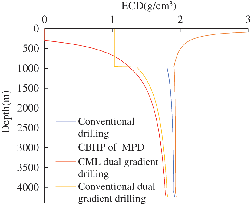
Figure 1: ECD trend line in the wellbore under different pressure control methods
3.2 The Law of the Influence of Pressure Control Parameters on ECD
3.2.1 ECD Curve Distribution for Controlling the Wellhead Back Pressure and Displacement under a Constant Bottom Hole Pressure
The control pressure parameters of CBHP managed pressure drilling are mainly the wellhead back pressure and displacement. Fig. 2 shows the variation of ECD with well depth: in the upper formation, the smaller the difference between the sum of the wellhead back pressure and annular pressure loss and the hydrostatic column pressure is, the greater the effect of wellhead back pressure on ECD. Therefore, the ECD of the upper formation varies greatly and decreases as the well depth increases. The ECD curve below 2000 m is almost vertically distributed, and the change is small. The ECD curve shifts to the right under different backpressure values, and the greater the wellhead backpressure value is, the more rightward the shift. The wellhead back pressure can change the ECD curve to a large extent, so that there is a larger ECD optimal interval to meet the complex formation in the lower part. Fig. 3 shows that the change in displacement is small over the entire depth of the well, and the controllable ECD range is small. Therefore, CBHP managed pressure drilling mainly changes the wellhead back pressure to adjust the ECD curve distribution to meet the deep narrow pressure profile formation.
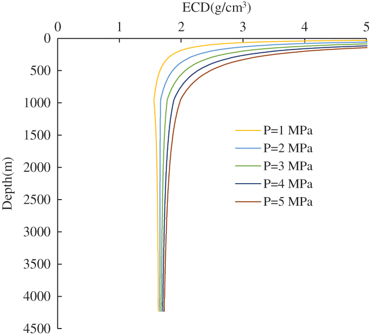
Figure 2: Distribution law of wellhead back pressure on the ECD under a constant bottom hole pressure
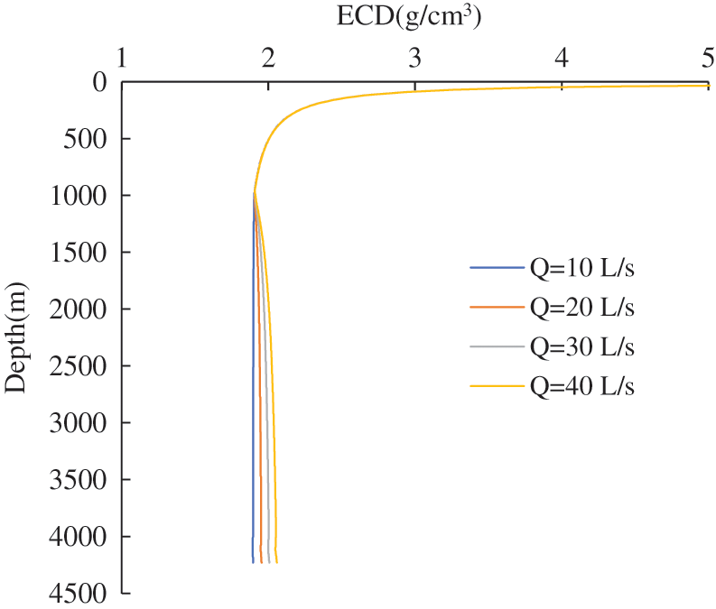
Figure 3: Distribution law of displacement on the ECD under a constant bottom hole pressure
3.2.2 Influence of Mud Depth and Displacement on the ECD Curve Distribution of CML Dual Gradient Control
The CML dual gradient drilling pressure management parameters are mainly the mud level depth and displacement. Fig. 4 shows that gas is above the standstill fluid in the riser, and the ECD is liable to be zero. The ECD value increases gradually with decreasing mud level depth. The ECD curve of the deep formation in CML dual-gradient drilling is gentler than that in CBHP managed pressure drilling. The controllable range of ECD is wider, which is more beneficial for drilling complex and narrow pressure formations in deep water. In Fig. 5, the ECD value also increases with increasing displacement, but the ECD value hardly changes with the change in the displacement in the upper formation, and there is only a small difference with increasing well depth. Therefore, the main pressure control parameter of CML dual-gradient drilling is the mud level depth, and the wellbore pressure can be accurately managed with displacement as an auxiliary means.
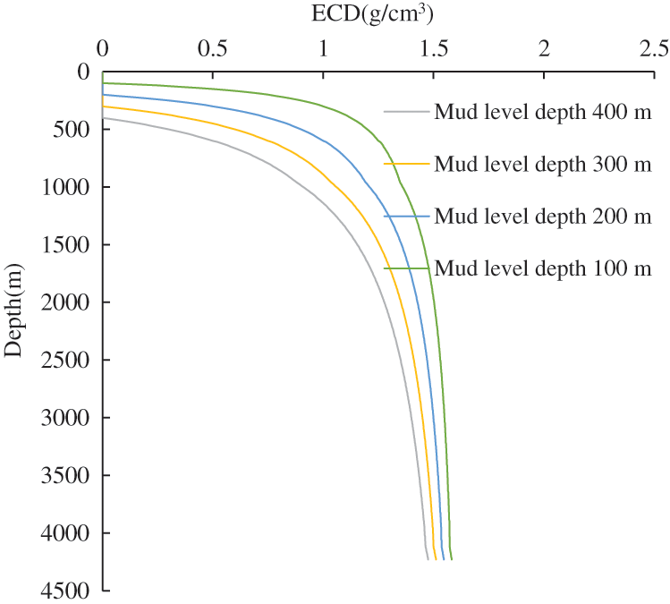
Figure 4: Distribution law of mud level depth on the ECD under CML dual gradient drilling conditions
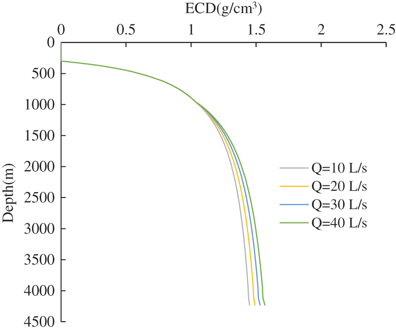
Figure 5: Displacement vs. ECD distribution rule under CML dual gradient drilling conditions
Fig. 6 shows that the greater the riser pump depth is, the smaller the ECD value. The riser pump depth is inversely proportional to the ECD. The riser pump depth and the mud level depth have similar effects on the ECD curve, but in practice the position of the riser pump cannot be changed once it is determined. Therefore, the mud level depth is the main pressure control parameter for CML dual gradient drilling.
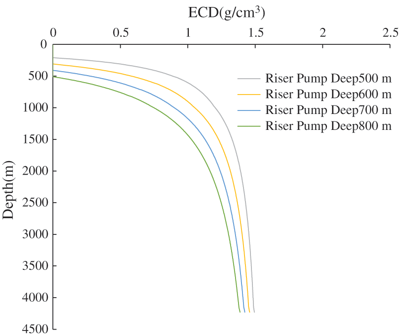
Figure 6: Distribution law of riser pump depth vs. ECD under CML dual gradient drilling conditions
4 Formation Adaptability Analysis of MPD
According to the ECD distribution law of different pressure control parameters, the two MPD methods have better formation adaptability than conventional drilling. Both kinds of managed pressure drilling can adapt to deep-water narrow pressure formations, but different narrow pressure profiles play a screening and decisive role in the adaptability of managed pressure drilling. Therefore, combined with two typical narrow pressure formation profiles in a deep water area, the adaptability of the two managed pressure drilling methods to different types of narrow pressure formation profiles was analyzed.
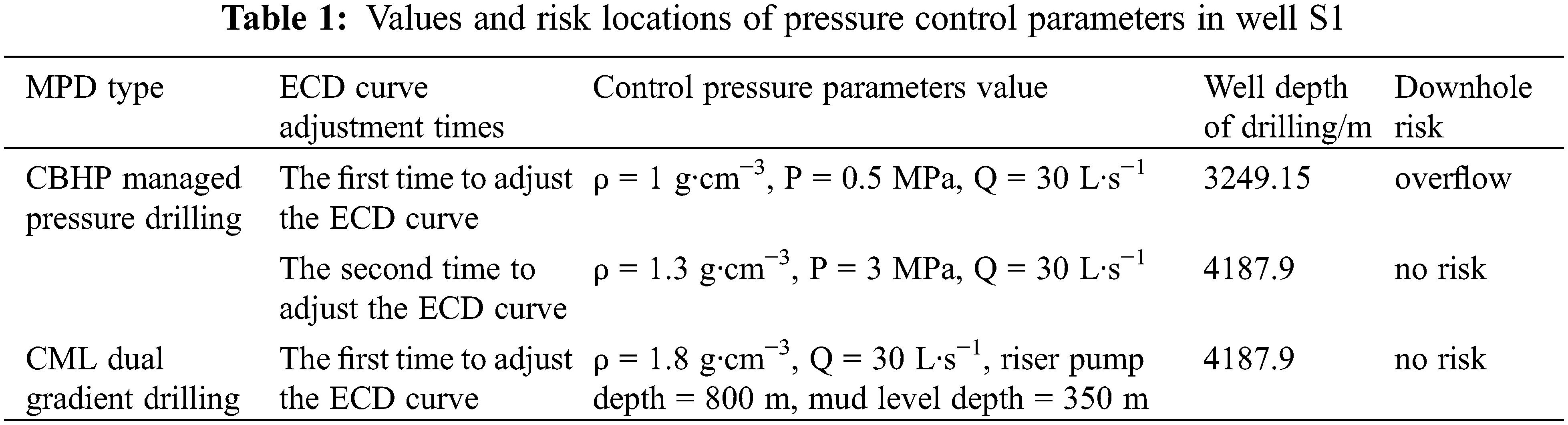
The characteristic of the formation pressure profile in Fig. 7 is that with the depth of the well increasing or decreasing synchronously, there are abnormal pressure intervals in the deep formation. Figs. 7 and 8 show the adaptability of the two types of managed pressure drilling in the deep-water S1 well after jet drilling at the seabed mudline. The results show that CBHP managed pressure drilling needs to adjust the ECD curve twice, and the first time the ECD curve is adjusted to a certain depth, it will be lower than the formation pore pressure. Kick risk occurs if the ECD curve is not readjusted. CML dual gradient drilling only needs to adjust the ECD curve once to reach the target well depth without downhole risk. After jet drilling near the 1000 m mud line, well S1 can be drilled down to a depth of approximately 3249.15 m in one drilling using CBHP managed pressure drilling, and to a depth of 4187.9 m in the target well in the second drilling. On the other hand, well S1 can be drilled down to 4187.9 m at one time after using the CML dual gradient drilling jet to drill into the surface layer. By comprehensively adjusting the number of ECD curves, the depth and downhole risk, the formation under this pressure profile is more applicable for CML dual gradient drilling. The locations of downhole risks are shown in Table 1 below.
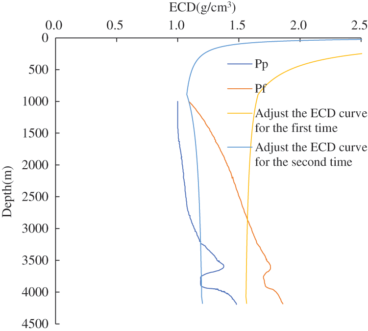
Figure 7: The adaptability of CBHP managed pressure drilling to the deep-water S1 well
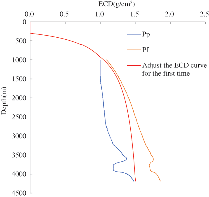
Figure 8: The adaptability of CML dual gradient drilling to the deep-water S1 well
The formation pressure profile of deep-water well B2 is characterized by a relatively uniform pressure increase in the upper formation as the well depth increases. In the deep formation, with increasing well depth, the formation fracture decreases, and the formation pore pressure increases, forming a narrow pressure window. Figs. 9 and 10 show that the managed pressure drilling ECD with CBHP drilling after jet drilling can be well adapted to the narrow pressure formation with a leftward shift in the lower part, and it can be drilled down to the target layer at one time or even deeper. The ECD curve of CML dual-gradient drilling trends to the right, which leads to the need to adjust the ECD curve multiple times, otherwise, the risk of lost circulation will be greater than the formation fracture pressure. Therefore, CBHP managed pressure drilling of this formation pressure profile has good adaptability to the formation, while CML dual gradient drilling has poor adaptability to the formation. The locations of downhole risks are shown in Table 2 below.
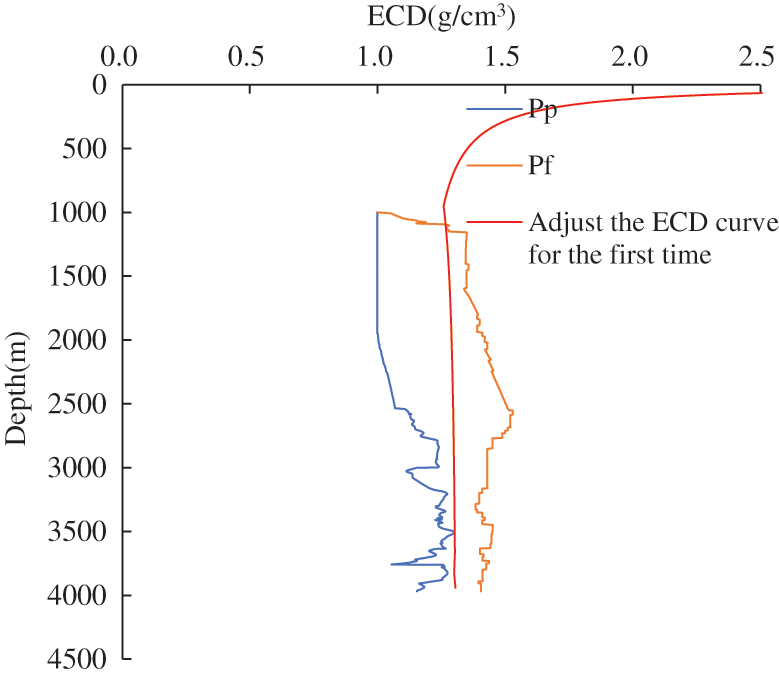
Figure 9: The adaptability of CBHP managed pressure drilling in the deep-water B2 well
Figure 10: The adaptability of CML dual gradient drilling in the deep-water B2 well
CBHP managed pressure drilling and CML dual gradient drilling ECD calculation models are established to study the influence of pressure control parameters on the two managed pressure drilling methods. The results show that the wellhead back pressure and displacement are proportional to the ECD in MPD with CBHP. In CML dual gradient drilling, the mud level depth and riser pump depth are inversely proportional to the ECD value and proportional to the displacement. The wellhead back pressure is the main pressure control parameter for CBHP managed pressure drilling, and the mud level depth is the main pressure control parameter for CML dual gradient drilling. Displacement can be used as an auxiliary means for the two pressure control methods. Based on the ECD curve trend of multiple drilling methods and the ability to adjust the ECD curve, managed pressure drilling is much more satisfactory for deep water and narrow pressure formations.
The applicability of the two pressure control methods is analyzed based on two typical pressure profiles common in deep water areas and combined with the ECD curve. Taking well S1 as an example, the formation pressure in this type of deep water increases or decreases synchronously with the depth of the well, and there is a pressure reversal formation. CBHP managed pressure drilling needs to adjust the ECD curve twice; if not, there is a kick risk. CML dual gradient drilling only needs to adjust the ECD curve once to go down to the target well depth without risk. Hence, this type of formation pressure profile is more suitable for CML dual gradient drilling. Taking well B2 as an example, the characteristics of this type of deep-water formation pressure are that the upper formation pressure increases with increasing well depth, the lower formation fracture pressure has a significant decreasing trend, and the lower formation pressure profile shifts to the left as a whole. This kind of formation pressure has good applicability to CBHP managed pressure drilling, which can drill into the target well or even deeper at one time. In contrast, CML dual gradient drilling needs to adjust the ECD curve several times to meet the bottom depth; otherwise, there will be a risk of lost circulation. Therefore, this type of formation pressure profile is more suitable for CBHP managed pressure drilling.
The wellhead back pressure is in the range of 0–3 MPa, and the mud level depth is in the range of 200–500 m. Judgments of the formation pressure of each well in advance pave the way for research on the adaptability of managed pressure drilling technology. The two typical pressure profiles account for more than 95% of the pressure profile types in deep-water areas and contribute to the selection and analysis of subsequent pressure management methods and well structure optimization.
Funding Statement: The authors received no specific funding for this study.
Conflicts of Interest: The authors declare that they have no conflicts of interest to report regarding the present study.
1. Sadicon, T., Henry, W. C., Robert, D. G. (2014). Riser gas risk mitigation with advanced flow detection and managed pressure drilling technologies in deepwater operations in Australia. The APPEA Journal, 12, 23–65. [Google Scholar]
2. Dow, B., Kamps, C., Baker, J. (2018). Design and manufacture of an original equipment manufacturer deepwater managed pressure drilling integrated solution. Society of Petroleum Engineers, 20, 52–62. DOI 10.2118/189645-MS. [Google Scholar] [CrossRef]
3. Kinik, K., Gumus, F., Osayande, N. (2015). Automated dynamic well control with managed-pressure dilling: A case study and simulation analysis. SPE Drilling & Completion, 30(2), 110–118. DOI 10.2118/168948-PA. [Google Scholar] [CrossRef]
4. Wang, G., Fan, H., Liu, G. (2011). Design and calculation of bottom hole normal pressure managed pressure drilling. Petroleum Exploration and Development, 38, 103–108. [Google Scholar]
5. Li, W., Hou, S., Lan, K. (2009). Key technologies and research status of adaptive control pressure drilling. Natural Gas Industry, 29, 50–52+140. [Google Scholar]
6. Zheng, J. (2017). Simulation and calculation of key parameters of dual gradient drilling. Chengdu: Southwest Petroleum University. [Google Scholar]
7. Shao, B. (2013). Research on key technologies of adaptive control pressure drilling. China Petroleum and Chemical Standards and Quality, 33. [Google Scholar]
8. Carpenter, C. (2014). Managed-pressure-drilling technology succeeds in the harding field. Journal of Petroleum Technology, 66(5), 138–141. DOI 10.2118/0514-0138-JPT. [Google Scholar] [CrossRef]
9. Records, L. R. (1972). Mud system and well control. Petroleum Engineering, 44, 97–108. [Google Scholar]
10. Baten, R., Cohen, J., Gaassand, S. (2016). Installation of a controlled mud level managed pressure drilling system onto a MODU. Society of Petroleum Engineers, 17, 5–12. DOI 10.2118/179499-MS. [Google Scholar] [CrossRef]
11. Li, J. (2016). Research on wellbore flow law and well control technology of dual-gradient drilling in deep-water controllable mud level. Beijing: China University of Petroleum (Beijing). [Google Scholar]
12. Wang, G., Jiang, H., Lian, Z. (2017). CAML drilling method-a new dual gradient drilling technology. International Petroleum and Petrochemical Technology Conference Proceedings, vol. 12, pp. 10–25. [Google Scholar]
13. Liu, S., Ren, M., Li, J. (2020). Adaptability analysis of my country’s marine managed pressure drilling technology. China Offshore Oil & Gas, 32, 129–136. [Google Scholar]
14. Wang, J., Fei, J. (2013). Discussion on the adaptability of underbalanced and managed pressure drilling in Jiangsu oilfield. Western Exploration Engineering, 25, 85–86+89. [Google Scholar]
15. Landet, I. S., Pavlov, A., Aamo, O. M. (2012). Control of heave-induced pressure fluctuations in managed pressure drilling. 2012 American Control Conference (ACC), vol. 6, pp. 25–36. DOI 10.1109/ACC.2012.6314622. [Google Scholar] [CrossRef]
16. Corre, B., Eymard, R., Guenot, A. (1984). Numerical computation of temperature distribution in a wellbore while drilling. Annual Technical Conference and Exhibition, 4, 6–19. [Google Scholar]
17. Johnson, A., Piccolo, B., Pinkstone, H. (2017). Augmenting deep-water well control with managed pressure drilling equipment. Society of Petroleum Engineers, 23, 59–72. [Google Scholar]
18. Elahifar, B. (2017). Successful deep-water drilling MPD early kick detection and performing managed pressure cementing with CML controlled mud level system in GOM and North Sea. Society of Petroleum Engineers, 6, 47–53. DOI 10.2118/184627-MS. [Google Scholar] [CrossRef]
19. Lai, M. B. (2016). Deepwater dual gradient drilling wellbore ECD study. Beijing: China University of Petroleum (Beijing). [Google Scholar]
 | This work is licensed under a Creative Commons Attribution 4.0 International License, which permits unrestricted use, distribution, and reproduction in any medium, provided the original work is properly cited. |