| Fluid Dynamics & Materials Processing |
DOI: 10.32604/fdmp.2022.020424
ARTICLE
Application of Epoxy Coatings to Increase the Efficiency of Wax Oils Production
Scientific and Educational Center of Geology and Development of Oil and Gas Fields, Department of Oil and Gas Technologies, Perm National Research Polytechnic University, Perm, 614000, Russia
*Corresponding Author: Anton Kozlov. Email: anton.kozlov@girngm.ru
Received: 23 November 2021; Accepted: 12 January 2022
Abstract: When producing hydrocarbons, an important task relates to the optimization of the stock of the producing well. The main complications for wells in non-working mode are represented by the formation of asphalt-resin-paraffin deposits. This issue is one of the most common problems in the production and transportation of oil. A promising method to deal with these deposits is the application of smooth coatings made of epoxy polymers on the inner surface of the production well tubing. In this work, a number of laboratory studies were carried out on the “Cold Finger” installation to assess the effectiveness of this approach. These laboratory studies have shown that the efficiency related to smooth coatings is 27% while the resulting thermal conductivity ranges from 0.259 to 0.279 W/(m°C). These results demonstrate that this technology can reduce the amount of organic deposits and increase the temperature of oil.
Keywords: Wax deposits; smooth coatings; production tubing; well
Nomenclature
| | mass of the formed deposits, g; |
| | mass of the investigated oil sample, g; |
| | intensity of formation of wax deposits on the “cold” rod without coating, %; |
| | intensity of formation of wax deposits on the “cold” coated rod, %; |
| | coefficient of heat transfer, |
| | temperature of the inner surface of the hollow rod wall, |
| | reservoir temperature (fluid temperature at well bottom), |
| | geothermal gradient (taken to be 0.0172 °C/m); |
| | distance along the vertical from the bottom to the referred elementary section of the pipe, m; |
| | inner diameter of the pipe, m; |
| | elementary section of the pipe along its height, m; |
| | specific heat of the fluid, |
| | fluid density |
| | mean fluid flow velocity, |
| | area of the flow section of the pipe, |
| | change in fluid temperature in an elementary section of the pipe, |
Reservoir fluid is a multiphase mixture, during the production of which many complications may arise inside the tubing [1]. Examples of such complications are organic deposits, salt formation, hydrate formation, mechanical impurities, corrosion damage to oil and gas field equipment, etc. [2,3]. In the production of hydrocarbons, one of the main tasks of a subsoil user is to minimize these manifestations and, as a result, trouble-free production and transportation of formation fluid [4]. Modern mining conditions complicate the fulfillment of this task every year. Arrangement of offshore fields involves an increase in the length of the production well tubing, a decrease in the flow temperature, and an increase in pressure losses in the cleaning system [5–7]. A significant role is also influenced by the commissioning of fields with hard-to-recover hydrocarbon reserves and the transition of existing fields to later stages of development. Hard-to-recover deposits are characterized by unfavorable conditions of fluid occurrence, low filtration properties of the reservoir rock and deteriorated physical and chemical properties of the fluid [8,9]. These deposits make up a significant share of the reserves explored in the territory of the Russian Federation and, according to various estimates, make up from 60% to 75% [10,11]. The production of fluid from these fields requires increased economic investment. Fields moving to late stages of development are characterized by a significant deterioration in the technological parameters of oil production, such as reservoir pressure, water cut, the composition of the produced fluid, etc.
Currently, the most common problem in the Russian Federation is the formation of wax deposits. The formation of these deposits creates many problems for subsoil users, as it can complicate almost any process of oil production: production, transportation or primary preparation of a fluid. Basically, the formation of wax deposits is observed in the bottomhole formation zone, on the cold surface of the production tubing, line pipelines and reservoirs.
The main components of wax deposits are paraffinic and asphaltene hydrocarbons. Asphaltenes and resins are heavy wax components of crude oil that can be found in crude oil in varying amounts, however, the presence of these substances does not indicate the presence of complications in the production of this oil, since these substances are soluble in light hydrocarbons. Asphaltenes significantly affect the formation of organic deposits [12,13]. So, according to works [14,15], a small number of asphaltenes in oil (0.1% of the mass) can significantly affect its properties, significantly lower the gelation temperature and yield stress of the waxy model oil. Numerous studies have shown that the deposition rate changes with a change in the concentration of asphaltenes in oil [16–18]. This effect is achieved due to the fact that at low concentrations asphaltenes can also act as a natural pour point depressant or wax inhibitor [19,20]. In addition, these components can act as crystallization centers for wax deposits and change the structure of the formed deposits [21–23].
Another component of wax deposits are paraffins, which are a mixture of saturated hydrocarbons [24]. In reservoir conditions, all the considered components of wax deposits are in the form of separate molecules due to the high pressure, temperature and dissolution of associated petroleum gas in oil. The formation of wax deposits occurs when the oil temperature drops below the temperature of the onset of paraffin crystallization. At a given temperature, the first crystals of paraffin are released from the oil, which is often associated with a decrease in the intensity of molecular motion in the oil flow, the convergence of wax molecules and the formation of a crystal of deposits. The subsequent formation of deposits occurs due to accidental formation of crystals due to the bonding of paraffin molecules or a more common process caused by the presence of various crystallization centers in the oil. Asphaltenes, resins, finely dispersed rocks, and corrosion products can be just such crystallization centers [25]. It should also be noted that high values of the asphaltene content can have a depression effect on the formation of deposits due to the disturbance of the formation of the tape structure of paraffin and, thereby, reduce the dynamic viscosity of oil [26].
To date, many laboratory studies have been carried out aimed at determining the mechanism and factors affecting the formation of wax deposits. Many deposition mechanisms have been proposed so far, but molecular diffusion has been accepted as the dominant wax deposition mechanism [27,28]. The molecular diffusion mechanism implies that wax deposits crystallize near a cold surface, which creates a concentration gradient between that surface and the center of the stream. Due to this gradient, the wax molecules will move from high concentration to low concentration. The main factor in the formation of deposits is considered to be the temperature of the fluid flow since its decrease below the temperature of the onset of paraffin crystallization contributes to the formation and formation of aggregates and their further separation from the volume of oil. Determining the temperature of the onset of paraffin crystallization for a fluid is a difficult task, since this temperature is highly dependent on the content of light fractions in oil, including gases. When the pressure drops below the bubble point pressure, these fractions can be released into the gas phase, which can significantly increase the temperature of the onset of paraffin crystallization in oil. An increase in the intensity of wax deposits formation also occurs with an increase in the water cut of the produced fluid due to the involvement of the aqueous phase in the volume of sediments [29]. The roughness of the tubing surface and the speed of fluid movement along the tubing are also important. High roughness can intensify the adhesion of wax deposits and thus increase the rate of adhesion of the deposits, a high rate of fluid production can reduce the rate of formation of wax deposits due to the tearing of the formed deposits from the surface of the production tubing. The formation of wax deposits in the formation fluid flow leads to a change in the rheological parameters of the produced fluid: an increase in its viscosity, a decrease in fluidity. With a significant decrease in the temperature of oil transportation, oil solidification is possible due to the high degree of crystallization of wax deposits and the formation of a crystalline matrix. With an increase in the volume of deposits on the inner surface of the tubing, a significant decrease in the hydraulic radius can be noted, which leads to an increase in pressure in the production well and can lead to emergency situations [30].
Currently, there are many methods for dealing with wax deposits. The increasing prevalence of this problem has led to the emergence of many different methods to remove or reduce the accumulation rate of the deposits in question in the production tubing. Many of the methods under consideration are capable of showing high technological efficiency, however, the successful implementation of any technology depends, first of all, on the physicochemical properties of the formation fluid and the conditions for its production.
A promising method from the point of view of preventing the formation of wax deposits is the use of smooth inner tubing coatings of oil producing wells [31]. The roughness of such coatings can be 5–15 µm, while this value on the inner surfaces of linear pipelines ranges from 35 to 85 µm [32]. The technological efficiency of these coatings, in addition to low roughness, is also due to the low adhesion of the surface of smooth coatings and their heat-insulating properties [33]. Today, smooth coatings applied to oilfield tubular products can be divided into polymer coatings, glazed coatings, and alloyed coatings [34]. The use of polymer coatings is due to the low free surface energy and are represented by fluoroethylene polymers, silicone rubbers, acrylic copolymers, etc. [35,36]. The use of polymer coatings can facilitate the process of hydrocarbon production; however, it has significant limitations on the maximum operating temperature and creep strength [37]. The use of glazed coatings is due to their hydrophilicity and, therefore, high efficiency at a high water cut in the produced fluid. However, glazed coatings have a significant disadvantage–high fragility [38]. Alloying the inner surfaces of the production tubing provides increased strength values for pipes, couplings, low roughness, and surface energy of the surface. Alloying can take place with various rare earth metals, including zinc, tungsten, and others [39–41]. However, alloying pipes is an expensive operation. plastic pipes are another type of smooth coating. the use of such production tubing provides a decrease in the intensity of the formation of wax deposits, however, these pipes have low strength characteristics and, when the primary layer of deposits is formed, the intensity of wax deposits formation will become similar to a steel pipe [42]. Within the framework of this work, we will consider several polymer compositions applied to the inner surfaces of production wells tubing.
The purpose of this work is to develop a methodology for assessing the technological efficiency of the use of polymer (epoxy) coatings for production tubing. This technique consists of a number of laboratory studies and modeling the process of introducing this coating to the target well.
Evaluation of the technological efficiency of the use of epoxy coatings was carried out using the laboratory installation “Cold Finger” CF-4 (Fig. 1).
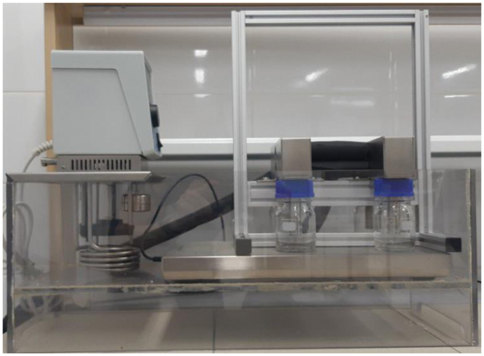
Figure 1: Image of the used laboratory installation “Cold Finger” CF-4
A distinctive feature of the installation under consideration is the method of fastening the “cold” rods to the installation body, namely the threaded connection. Due to this feature, it became possible to manufacture a “replaceable” rod with a smooth coating applied to its surface (Fig. 2). In this laboratory study, three different epoxy coatings were compared. As a part of this work, these epoxy coatings will be designated as coatings No. 1, No. 2 and No. 3, respectively. The production of these “replaceable” coatings was carried out by cleaning the original surface, applying a silicate-enamel coating or a mixture of coatings to the outer surface, then firing and drying the surface. The bases of the coatings considered in this work are for coating No. 1–a mixture of silicate enamels EST-2 and EST-7, for coating No. 2–enamel without primer 3ET-01-UT, for coating No. 3–silicate enamel MK-5. For each of the considered coatings, the thermal insulation properties were assessed according to the method described in [43].
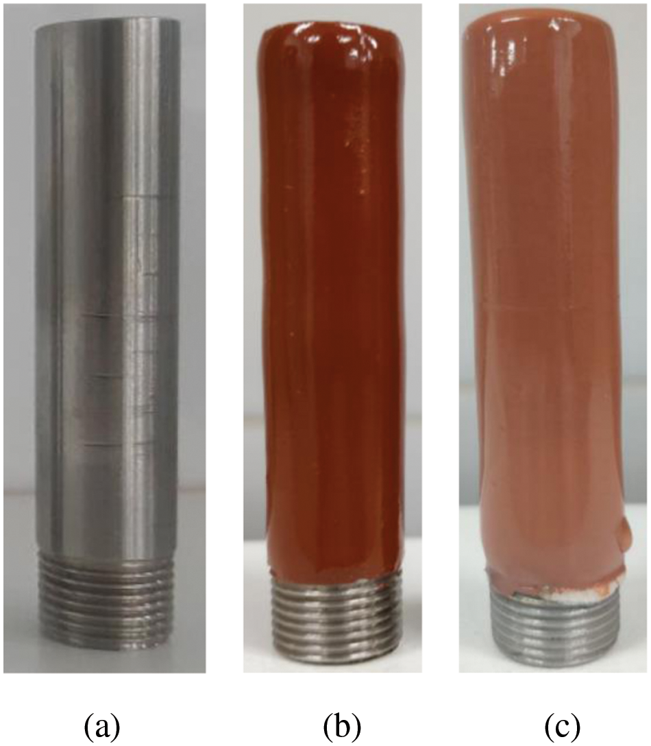
Figure 2: Image of a “cold” rod: a) Without a smooth coating; b) With a smooth coating No. 1; c) With a smooth coating No. 2
Laboratory research on the CF-4 “Cold Finger” installation was carried out according to the author’s methodology described in the work. Within the framework of laboratory studies, the kinetic characteristic of the formation of wax deposits was assessed–the intensity of the formation of wax deposits, determined by expression (1). The effectiveness of the use of a smooth coating was estimated by expression (2).
3 Modeling the Thermal Regime of the Target Well
To determine the temperature of conducting studies to assess the effectiveness of the application of the considered smooth coatings on the target oil well, it is necessary to simulate the temperature regime of this well. Also, this modeling is necessary to assess the effectiveness of the use of the considered coatings as a heat-insulating material.
Modeling the temperature distribution over the inner surface of the tubing was carried out according to the technique presented in [44]. The basis of this technique is the expression 3, the left-hand part of which represents the amount of heat transferred from the fluid (during lift of the recovered products) in an elementary section dh of the tubing string or of the hollow rod with its lateral surface area πD·dh and the right-hand part of which represents the amount of heat required for the change in temperature of the fluid during its l.
The solution of Eq. (3) has the form of Eq. (4):
where,
The use of this formula allows obtaining reliable information about the temperature distribution along the wellbore. The accuracy of the obtained temperature distribution is achieved through the use of correct initial data, the application of the known laws of heat and mass transfer. The presented technique has been tested in scientific work [45], where the comparison of model values and real thermogram of the well is carried out.
The results of the simulation are presented in Fig. 3 also show the distribution of the thickness of wax deposits in this well, taken on the basis of field data.
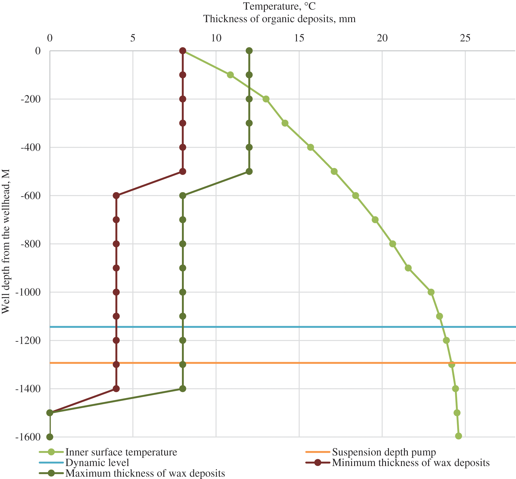
Figure 3: Temperature distribution along the target wellbore with indication of the thickness of the formed wax deposits
The technological properties of oil production by the target well and the physicochemical properties of the formation fluid are presented in Table 1. These data are the basis for modeling the temperature distribution along the wellbore.

Based on the temperature distribution along the wellbore, it can be concluded that the most intense process of formation of wax deposits in this well occurs at temperatures below 17°C. Laboratory studies to assess the intensity of the formation of wax deposits and the effectiveness of the use of smooth coatings should be carried out at temperatures from 8 to 17°C, since at these temperatures the highest intensity of the formation of wax deposition is observed.
4 Results of Laboratory Studies
The results of laboratory studies to assess the effectiveness of the use of smooth coatings, determined by expression (2), are shown in Fig. 4.
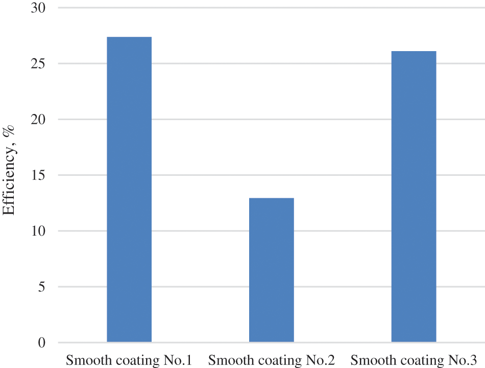
Figure 4: Efficiency of using smooth coatings
Based on the data of laboratory studies, it can be concluded that the most effective of the considered smooth coatings is coating No. 1. Coating No. 3 also showed a relatively high technological efficiency. It is worth noting the overall low efficiency of the considered smooth coatings, which does not exceed 27%. The reasons for this phenomenon may be different: low thickness of a smooth coating, the peculiarity of applying an epoxy composition to a “cold” rod, general low efficiency of these smooth coatings.
Separately, it should be clarified that the use of smooth coatings allows increasing the temperature of oil production, changing the carbon number distribution due to changes in the thermal field of the well, which will affect such properties of deposits as strength and aging rate [46–50]. However, the evaluation of these parameters in the framework of laboratory studies is impossible, as a result of which they will not be considered in this work. However, an assessment of the thermal insulation properties is possible and will be carried out further.
Photos of “cold” rods with wax deposits formed on them are shown in Figs. 5a–5c.
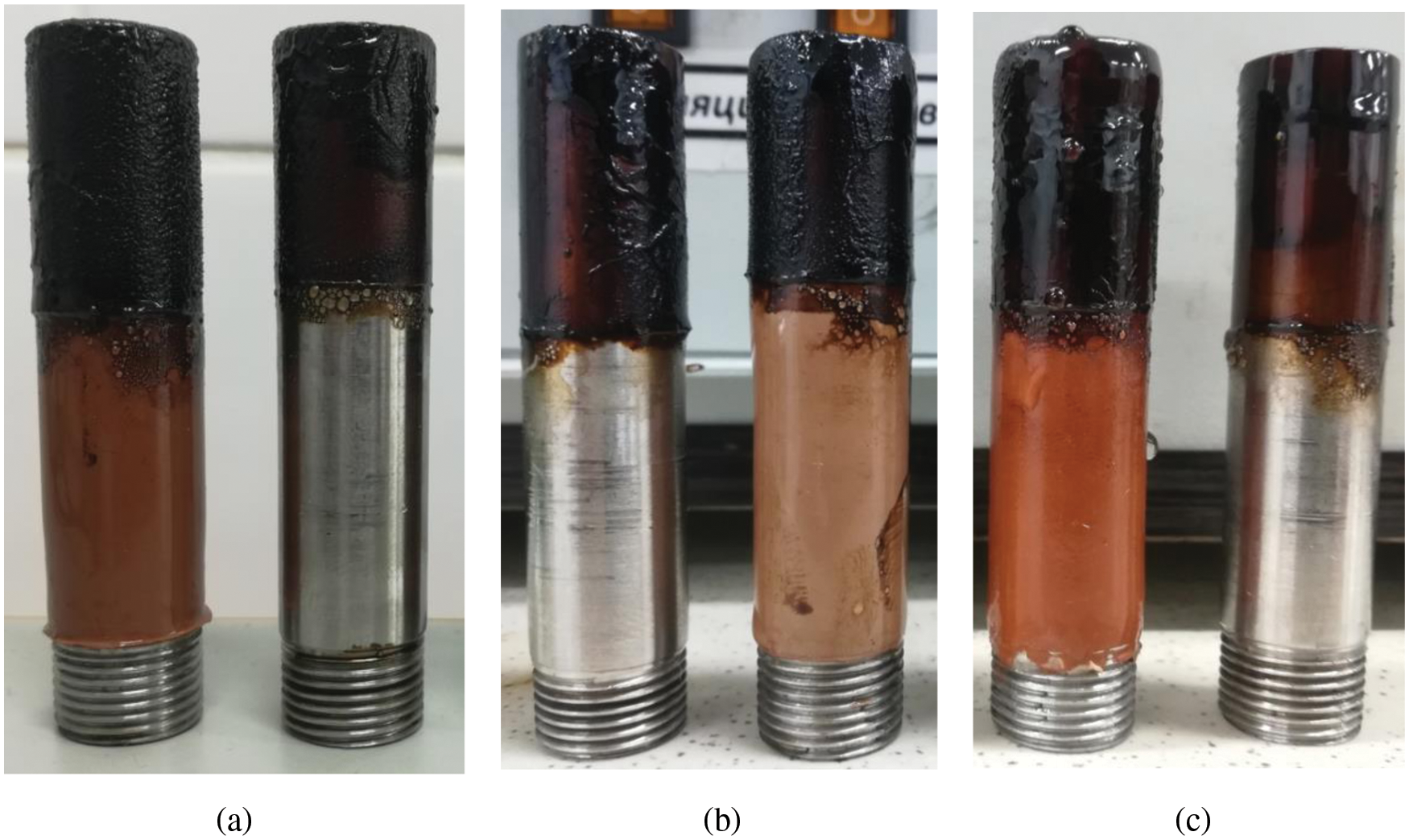
Figure 5: Photos of “cold” coated rods No. 1 (a), No. 2 (b) and No. 3 (c) After the formation of wax deposits
However, to assess the effectiveness of the application of the considered smooth coatings, it is also necessary to evaluate the thermal conductivity of these smooth coatings. For this purpose, the thermal conductivity coefficient will be determined for coating No. 1, which has shown the highest technological efficiency. Fig. 6 shows a graph of temperature changes on the surface of “cold” rods without coating and with coating No. 1.
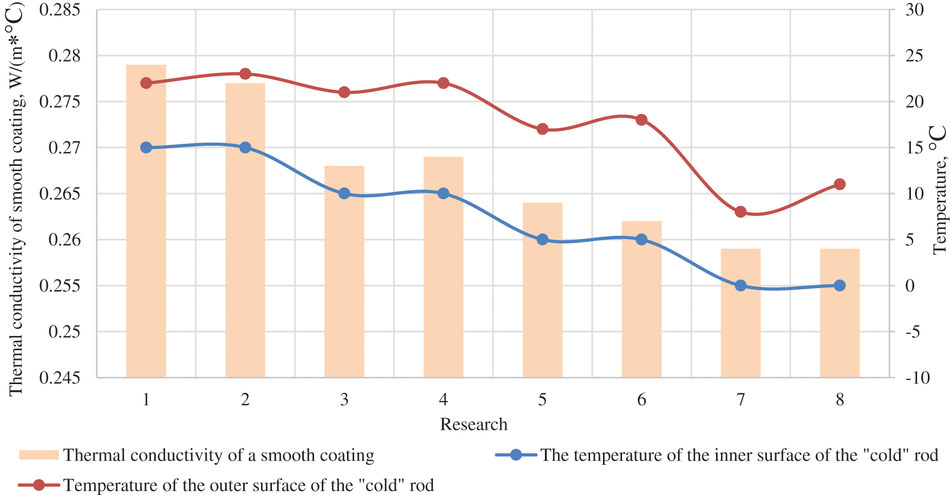
Figure 6: Assessment of thermal conductivity of smooth coating No. 1 at various temperatures
Analyzing this figure, it can be noted that the thermal conductivity of a smooth coating changes slightly with a change in the temperature of this coating. With a decrease in the surface temperature from 23°C to 8°C, a decrease in thermal conductivity by 6.49% is observed.
To assess the efficiency of using the considered smooth coating on the target well, a simulation of the change in the thermal mode of operation was carried out in comparison with an uncoated tubing string (Fig. 7). Within the framework of this simulation, the thermal conductivity of these deposits was taken equal to 0.265 W/(m∙°C), and the thickness of the coating applied to the inner surface of the tubing was 4 mm.
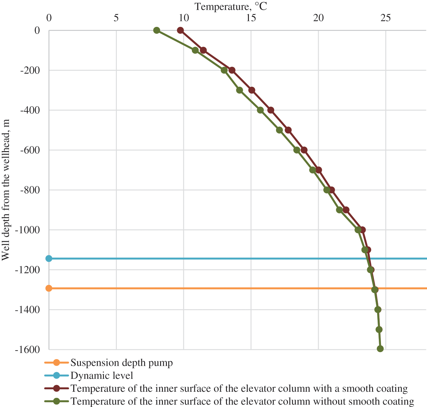
Figure 7: Temperature distribution along the target wellbore with indication of the thickness of the formed wax deposits
Analyzing the obtained curve, it can be noted that a slight increase in surface temperature is observed along the entire length of the tubing. The maximum increase is achieved towards the wellhead and is 1.76°C. In this case, in the interval of the most active paraffiogenesis (Fig. 3), the temperature increase is from 0.57 to 1.76°C. Thus, the introduction of this smooth coating contributes to an increase in the temperature of the inner surface of the tubing, which in turn can lead to a decrease in the intensity of the formation of wax deposits by reducing the temperature gradient between the cold surface of the production tubing and the hot produced fluid.
The formation of wax deposits on the inner surface of tubing strings is one of the most common complications in hydrocarbon production. The use of smooth inner coatings of production tubing allows to reduce the rate of formation of these deposits due to the low adhesion of the surface of smooth coatings and their heat-insulating properties.
The novelty of this work is the manufacture of a “replaceable” rod for «Cold Finger» installation with the application of a smooth coating on its surface. Currently, the study of these coatings is carried out on small flat samples or in the field. In [51–53], the results of studies of smooth coatings when applied to small plates and a study of the deposition of deposits on their surface are presented. The disadvantages of such studies are the inability to reproduce the field conditions of sediment formation. The work [54] presented the field results of the experience of using certain smooth coatings on real production wells. The disadvantage of this method is the high cost of their implementation and costly approbation of the quality of preventing the formation of deposits. The study of the paraffin formation process using a replaceable core allows the most correct modeling of the result of the introduction of this smooth coating, selection of various coatings and at the same time has a low production cost.
Analyzing the results of laboratory studies, it can be noted the low efficiency of the use of these coatings in order to reduce the intensity of the formation of wax deposits (up to 27%). Moreover, the composition showed the highest efficiency, the basis of which was a mixture of epoxy coatings est-2 and est-7. The assessment of the thermal insulation properties showed that these deposits have a rather low coefficient of thermal conductivity (0.259–0.279 w/(m∙°C), which allows them to be used as a thermal insulation material. The wellbore increases by an average of 0.5°C. Moreover, in the zone of the most intense formation of wax deposits, this increase is, on average, 0.92°C. These facts allow us to conclude that the introduction of the considered coatings is an effective technology that can reduce the intensity of wax deposits, reduce the roughness of the inner surface of the tubing and protect tubing from aggressive environment.
Funding Statement: The research was carried out at the expense of the Russian Science Foundation Grant No. 21-79-10403, https://rscf.ru/project/21-79-10403/.
Conflicts of Interest: The authors declare that they have no conflicts of interest to report regarding the present study.
1. Towler, B. F., Jaripatke, O., Mokhatab, S. (2011). Experimental investigations of the mitigation of paraffin wax deposition in crude oil using chemical additives. Petroleum Science and Technology, 29(5), 468–483. DOI 10.1080/10916460903394029. [Google Scholar] [CrossRef]
2. Ilyushin, P. Yu, Vyatkin, K. A., Kozlov, A. V. (2022). Oil component composition influence on thermal conductivity of formed organic deposits. Bulletin of the Tomsk Polytechnic University, Geo Аssets Engineering, 333(2), 90–97. DOI 10.18799/24131830/2022/2/3299. [Google Scholar] [CrossRef]
3. Vyatkin, K. A., Ilushin, P. Y., Kozlov, A. V. (2021). Forecasting the value of the linear pipeline cleaning interval based on the laboratory research. International Review of Mechanical Engineering, 15(6), 294–300. DOI 10.15866/ireme.v15i6.20811. [Google Scholar] [CrossRef]
4. Murawski, S. A., Ainsworth, C. H., Gilbert, S., Hollander, D. J., Paris, C. B. et al. (2019). Scenarios and responses to future deep oil spills: Fighting the next war. Switzerland: Springer. [Google Scholar]
5. Khasanov, I. I., Shakirov, R. A., Gilmutdinov, T. D. (2019). Application of a model of an effective heat conduction medium for modeling the fallout of ARPD in offshore oil pipelines. Transportation and Storage of Petroleum Products and Hydrocarbon Raw Materials, 1, 17–23. DOI 10.24411/0131-4270-2019-10104. [Google Scholar] [CrossRef]
6. Lochte, G. (1993). Technique and technology of application in pipelines of cleaning pistons, pistons-separators and in-line flaw detectors. Oil, Gas and Petrochemicals Abroad, 5, 21–30. [Google Scholar]
7. Kosyak, D. V., Markin, A. N. (2011). Experience in combating deposits of ARPD in subsea pipelines of the Sakhalin-2 project. Territory of Oil and Gas, 6, 78–87. [Google Scholar]
8. Jing, J., Sun, J., Huang, H., Zhang, M., Wang, C. et al. (2019). Facilitating the transportation of highly viscous oil by aqueous foam injection. Fuel, 251(4), 763–778. DOI 10.1016/j.fuel.2019.03.116. [Google Scholar] [CrossRef]
9. Yang, H., Duan, Y. X. (2014). A feasibility study on in-situ heating of oil shale with injection fluid in China. Journal of Petroleum Science and Engineering, 122(5), 304–317. DOI 10.1016/j.petrol.2014.07.025. [Google Scholar] [CrossRef]
10. Soto-Cortes, G., Pereyra, E., Sarica, C., Rivera-Trejo, F., Torres, C. (2019). Effects of high oil viscosity on oil-gas upward flow behavior in deviated pipes. Experimental Thermal and Fluid Science, 109, 109896. DOI 10.1016/j.expthermflusci.2019.109896. [Google Scholar] [CrossRef]
11. Vishnumolakala, N., Zhang, J., Ismail, N. B. (2020). A comprehensive review of enhanced oil recovery projects in Canada and recommendations for planning successful future EOR projects. SPE Canada Heavy Oil Conference. OnePetro. [Google Scholar]
12. Tinsley, J. F., Prud’homme, R. K. (2010). Deposition apparatus to study the effects of polymers and asphaltenes upon wax deposition. Journal of Petroleum Science and Engineering, 72(1–2), 166–174. DOI 10.1016/j.petrol.2010.03.014. [Google Scholar] [CrossRef]
13. Syed, F. I., Boukhatem, M., Al Kiyoumi, A. A. (2019). Lean HC gas injection pilots analysis and IPR back calculation to examine the impact of asphaltene deposition on flow performance. Petroleum Research, 4(1), 84–95. DOI 10.1016/j.ptlrs.2018.11.006. [Google Scholar] [CrossRef]
14. Venkatesan, R., Östlund, J. A., Chawla, H., Wattana, P., Nydén, M. et al. (2003). The effect of asphaltenes on the gelation of waxy oils. Energy & Fuels, 17(6), 1630–1640. DOI 10.1021/ef034013k. [Google Scholar] [CrossRef]
15. Yang, F., Zhu, H., Li, C., Yao, B., Wang, F. et al. (2021). Investigation on the mechanism of wax deposition inhibition induced by asphaltenes and wax inhibitors. Journal of Petroleum Science and Engineering, 204(7), 108723. DOI 10.1016/j.petrol.2021.108723. [Google Scholar] [CrossRef]
16. Li, H., Zhang, J., Xu, Q., Hou, C., Sun, Y. et al. (2020). Influence of asphaltene on wax deposition: Deposition inhibition and sloughing. Fuel, 266(7), 117047. DOI 10.1016/j.fuel.2020.117047. [Google Scholar] [CrossRef]
17. Tinsley, J. F., Prud’homme, R. K., Guo, X., Adamson, D. H., Callahan, S. et al. (2007). Novel laboratory cell for fundamental studies of the effect of polymer additives on wax deposition from model crude oils. Energy & Fuels, 21(3), 1301–1308. DOI 10.1021/ef060446m. [Google Scholar] [CrossRef]
18. Lei, Y., Han, S., Zhang, J. (2016). Effect of the dispersion degree of asphaltene on wax deposition in crude oil under static conditions. Fuel Processing Technology, 146, 20–28. DOI 10.1016/j.fuproc.2016.02.005. [Google Scholar] [CrossRef]
19. Ariza, E., Chaves-Guerrero, A., Molina, V. D. (2018). Effect of average molecular parameters of asphaltenes on the rheological properties of crude oils from Colorado oil field. Energy & Fuels, 32(6), 6557–6564. DOI 10.1021/acs.energyfuels.8b00664. [Google Scholar] [CrossRef]
20. Alcazar-Vara, L. A., Garcia-Martinez, J. A., Buenrostro-Gonzalez, E. (2012). Effect of asphaltenes on equilibrium and rheological properties of waxy model systems. Fuel, 93(13), 200–212. DOI 10.1016/j.fuel.2011.10.038. [Google Scholar] [CrossRef]
21. Li, C., Zhu, H., Yang, F., Liu, H., Wang, F. et al. (2019). Effect of asphaltene polarity on wax precipitation and deposition characteristics of waxy oils. Energy & Fuels, 33(8), 7225–7233. DOI 10.1021/acs.energyfuels.9b01464. [Google Scholar] [CrossRef]
22. Li, C., Cai, J., Yang, F., Zhang, Y., Bai, F. et al. (2016). Effect of asphaltenes on the stratification phenomenon of wax-oil gel deposits formed in a new cylindrical Couette device. Journal of Petroleum Science and Engineering, 140, 73–84. DOI 10.1016/j.petrol.2016.01.004. [Google Scholar] [CrossRef]
23. Yang, F., Cai, J., Cheng, L., Li, C., Ji, Z. et al. (2016). Development of asphaltenes-triggered two-layer waxy oil gel deposit under laminar flow: An experimental study. Energy & Fuels, 30(11), 9922–9932. DOI 10.1021/acs.energyfuels.6b01482. [Google Scholar] [CrossRef]
24. Krivoshchekov, S. N., Vyatkin, K. A., Kozlov, A. V. (2021). Modeling of asphaltene-resin-wax deposits formation in a string of hollow rods during simultaneous separate operation of two oil reservoirs. Chemical and Petroleum Engineering, 57(3–4), 213–219. DOI 10.1007/s10556-021-00920-1. [Google Scholar] [CrossRef]
25. Hammami, A., Raines, M. A. (1997). Paraffin deposition from crude oils: Comparison of laboratory results to field data. SPE Annual Technical Conference and Exhibition. DOI 10.2118/54021-PA. [Google Scholar] [CrossRef]
26. Dobbs, J. B. (1999). A unique method of paraffin control in production operations. SPE Rocky Mountain regional meeting. DOI 10.2118/55647-MS. [Google Scholar] [CrossRef]
27. Burger, E. D., Perkins, T. K., Striegler, J. H. (1981). Studies of wax deposition in the trans-Alaska pipeline. Journal of Petroleum Technology, 33(6), 1–075. DOI 10.2118/8788-PA. [Google Scholar] [CrossRef]
28. Leiroz, A. T., Azevedo, L. F. A. (2005). Studies on the mechanisms of wax deposition in pipelines. Offshore Technology Conference. [Google Scholar]
29. Vyatkin, K., Mordvinov, V., Ilushin, P., Kozlov, A. (2021). Influences of the water cut of pumping oil and the mineralization of the associated water on the rate of sludging. Applied Sciences, 11(15), 6678. DOI 10.3390/app11156678. [Google Scholar] [CrossRef]
30. Ilushin, P., Vyatkin, K., Kozlov, A. (2022). Development of an approach for determining the effectiveness of inhibition of paraffin deposition on the wax flow loop laboratory installation. Inventions, 7(1), 3. DOI 10.3390/inventions7010003. [Google Scholar] [CrossRef]
31. Ilyushin, P. Y., Vyatkin, K. A., Kozlov, A. V., Votinova, A. O. (2021). Methodology for evaluation of organic deposits thermal conduction using laboratory facility Wax Flow Loop. Science & Technologies: Oil and Oil Products Pipeline Transportation, 11(6), 622–629. DOI 10.28999/2541-9595-2021-11-6-622-629. [Google Scholar] [CrossRef]
32. McDonnell, M. R. (2011). Liquid applied internal flow coatings for oil transmission lines. 1st Pipeline Technology Conference. [Google Scholar]
33. Charles, J. G., Settineri, W. J. (1985). Water-wet surfaces for long-term paraffin inhibition. SPE Eastern Regional Meeting. DOI 10.2118/14520-MS. [Google Scholar] [CrossRef]
34. Sun, Y., Li, S., Sun, R., Zhang, Q., Zhang, B. et al. (2020). Dynamic experimental study on the paraffin deposition prevention performance of tungsten alloy coating pipe in simulating vertical wellbore. ACS Omega, 5(36), 23284–23288. DOI 10.1021/acsomega.0c03002. [Google Scholar] [CrossRef]
35. Boot, J. C., Toropova, I. L., Javadi, A. A. (2003). Predicting the creep lives of thin-walled cylindrical polymeric pipe linings subject to external pressure. International Journal of Solids and Structures, 40(26), 7299–7314. DOI 10.1016/S0020-7683(03)00440-2. [Google Scholar] [CrossRef]
36. Zhang, X., Tian, J., Wang, L., Zhou, Z. (2002). Wettability effect of coatings on drag reduction and paraffin deposition prevention in oil. Journal of Petroleum Science and Engineering, 36(1–2), 87–95. DOI 10.1016/S0920-4105(02)00267-X. [Google Scholar] [CrossRef]
37. Zhu, L., Zhai, J. Y., Li, W., Liu, H. C. (2011). Study of paraffin wax inhibtion film based on surface composition and microstructure. Transactions of Materials and Heat Treatment, 32(4), 144–148. DOI 10.13289/j.issn.1009-6264.2011.04.003. [Google Scholar] [CrossRef]
38. Li, M., Su, J., Wu, Z., Yang, Y., Ji, S. (1997). Study of the mechanisms of wax prevention in a pipeline with glass inner layer. Colloids and Surfaces A: Physicochemical and Engineering Aspects, 123, 635–649. DOI 10.1016/S0927-7757(96)03776-4. [Google Scholar] [CrossRef]
39. Shao, N., Dai, J. W., Li, G. Y., Nakae, H., Hane, T. (2004). Effect of La on the wettability of Al2O3 by molten aluminum. Materials Letters, 58(14), 2041–2044. DOI 10.1016/j.matlet.2003.12.023. [Google Scholar] [CrossRef]
40. Wang, Z., Zhu, L., Liu, H., Li, W. (2012). Investigation on the paraffin prevention performance of lanthanum-modified zinc powder. Applied Surface Science, 259(3–4), 1–6. DOI 10.1016/j.apsusc.2012.05.038. [Google Scholar] [CrossRef]
41. Jorda, R. M. (1966). Paraffin deposition and prevention in oil wells. Journal of Petroleum Technology, 18(12), 1–605. DOI 10.2118/1598-PA. [Google Scholar] [CrossRef]
42. Al-Yaari, M. (2011). Paraffin wax deposition: Mitigation and removal techniques. SPE Saudi Arabia Section Young Professionals Technical Symposium. DOI 10.2118/155412-MS. [Google Scholar] [CrossRef]
43. Kozlov, A. V., Vyatkin, K. A. (2020). Assessment of ARPD thermal conductivity based on laboratory research results. Master’s Journal, 1, 69–76. [Google Scholar]
44. Vyatkin, K. A., Kozlov, A. V., Ilyushin, P. Yu (2020). A method for predicting changes in the intensity of asphaltene-resin-paraffin deposits formation in an oil production well. Petroleum Engineer, 4, 38–45. [Google Scholar]
45. Korobov, G. Y., Mordvinov, V. A. (2013). Distribution of temperature along the shaft of a producing well. Oil Industry, 4, 57–59. [Google Scholar]
46. Chi, Y., Daraboina, N., Sarica, C. (2016). Investigation of inhibitors efficacy in wax deposition mitigation using a laboratory scale flow loop. AIChE Journal, 62(11), 4131–4139. DOI 10.1002/aic.15307. [Google Scholar] [CrossRef]
47. Fan, K., Li, S., Li, R. (2021). Development of wax molecular diffusivity correlation suitable for crude oil in wax deposition: Experiments with a cold-finger apparatus. Journal of Petroleum Science and Engineering, 205(7), 108851. DOI 10.1016/j.petrol.2021.108851. [Google Scholar] [CrossRef]
48. Lu, Y., Huang, Z., Hoffmann, R., Amundsen, L., Fogler, H. S. (2012). Counterintuitive effects of the oil flow rate on wax deposition. Energy & Fuels, 26(7), 4091–4097. DOI 10.1021/ef3002789. [Google Scholar] [CrossRef]
49. Ehsani, S., Mehrotra, A. K. (2020). Effects of shear rate and time on deposit composition in the cold flow regime under laminar flow conditions. Fuel, 259(3), 116238. DOI 10.1016/j.fuel.2019.116238. [Google Scholar] [CrossRef]
50. Chi, Y., Daraboina, N., Sarica, C. (2017). Effect of the flow field on the wax deposition and performance of wax inhibitors: Cold finger and flow loop testing. Energy & Fuels, 31(5), 4915–4924. DOI 10.1021/acs.energyfuels.7b00253. [Google Scholar] [CrossRef]
51. Quintella, C. M., Musse, A. P. S., Castro, M. T., Scaiano, J. C., Mikelsons, L. et al. (2006). Polymeric surfaces for heavy oil pipelines to inhibit wax deposition: PP, EVA28, and HDPE. Energy & Fuels, 20(2), 620–624. DOI 10.1021/ef050267p. [Google Scholar] [CrossRef]
52. Bai, J., Jin, X., Wu, J. T. (2019). Multifunctional anti-wax coatings for paraffin control in oil pipelines. Petroleum Science, 16(3), 619–631. DOI 10.1007/s12182-019-0309-7. [Google Scholar] [CrossRef]
53. Wang, Z., Zhu, L., Liu, H., Li, W. (2013). A conversion coating on carbon steel with good anti-wax performance in crude oil. Journal of Petroleum Science and Engineering, 112(7), 266–272. DOI 10.1016/j.petrol.2013.11.013. [Google Scholar] [CrossRef]
54. Anisuzzaman, S. M., Fong, Y. W., Madsah, M. (2018). A review on various techniques and recent advances in polymeric additives to mitigate wax problems in crude oil. Journal of Advanced Research in Fluid Mechanics and Thermal Sciences, 48(1), 53–64. [Google Scholar]
 | This work is licensed under a Creative Commons Attribution 4.0 International License, which permits unrestricted use, distribution, and reproduction in any medium, provided the original work is properly cited. |