| Fluid Dynamics & Materials Processing |
DOI: 10.32604/fdmp.2022.020294
ARTICLE
Analysis of the Weight Loss of High Temperature Cement Slurry
College of Petroleum Engineering, Yangtze University, Wuhan, 430199, China
*Corresponding Author: Zhiqiang Huang. Email: 18772645696@163.com
Received: 15 November 2021; Accepted: 15 March 2022
Abstract: The weight loss of cement slurry is the main cause of early annular air channeling and accurate experimental evaluation of the law of loss change is the key to achieve compression stability and prevent this undesired phenomenon. Typically, tests on the pressure loss of cement slurry are carried out for temperature smaller than 120°C, and this condition cannot simulate effectively the situation occurring in high temperature wells. For this reason, in this study a series of experimental tests have been conducted considering a larger range of temperatures, different retarders and fluid loss additives. The results show that with an increase in the temperature, the weight loss curve of cement slurry changes from a “two-stage” to a “three-stage” behavior, and the risk of channeling increases accordingly. On increasing the amount of retarder and fluid loss additive, the transition time of cement slurry displays a non-monotonic behavior (it decreases first and then increases). It is found that the optimized retarder and fluid loss additive dosage are 0.2% and 2.5%, respectively.
Keywords: Cementing; weight loss test; weight loss law; cement slurry; evaluation; anti-gas channeling
Cementing is one of the very important links in the process of oil exploration and development. Cementing quality directly influences subsequent drilling engineering and mining. A series of physical and chemical changes will occur during the cement slurry waiting period after cementing. From the beginning of hydration to the end of solidification, the pressure of a cement slurry column continuously decreases due to the weight loss of the cement slurry. When the pressure of the cement slurry column is lower than the formation pressure here, the oil, gas and water in the formation can invade into the annular space and cause channeling [1,2]. The generation of annular air channeling will not only destroy the cementing quality, but also lead to uncontrollable blowout accidents, resulting in waste of oil and gas resources and serious damage to the environment. There is consensus in the literature that the weight loss for cement slurry is one of the important factors leading to annulus channeling, and for special high temperature environments, the annulus channeling caused by weight loss is particularly significant [3–5]. Therefore, it is of great significance to effectively measure and calculate the variation in cement slurry pressure loss under high-temperature conditions for the establishment of a slurry channeling prevention experiment method and evaluation of the channeling prevention performance of high-temperature cement slurries. Liu et al. [6] used the anti-channeling evaluation device developed by the method of proportional reduction to experimentally evaluate the anti-channeling performance of cement slurry, and summarized a set of preliminary optimization standards for the anti-channeling performance of cement slurry. Zhu et al. [7,8] and others comprehensively investigated the influence of various factors on the weight loss of cement slurry through a self-developed weight loss simulation experimental device, and proposed corresponding compression stability and anti-channeling methods. Zhao et al. [9] established an accurate calculation model of hydraulic pressure loss of slurry and a developed sectional design and balanced cementing methods, which provided an effective calculation model for anti-gas channeling cementing design. Teng et al. [10] investigated the evolution of cement slurry properties during liquid–solid transition by tests using X-ray diffraction (XRD), thermogravimetry (TG) and mechanical analysis and explained the causes of pressure loss in cement slurry from a microscopic point of view. Carter et al. [11] developed a set of pressure loss evaluation device for high-temperature and high-pressure cement slurry by using the method of equal scale reduction, and carried out the pressure loss test of typical cement slurry in vertical and inclined wells, which solved the problem of weight loss pressure test of cement slurry under casing eccentricity and high pressure. However, the above research has not considered the weight loss law for cement slurry at high temperature, and the influence of cement slurry additives on the anti-channeling performance is not well understood.
In this regard, based on the use of a weight loss pressure test device for high-temperature cement slurry, we carried out pressure loss tests for a set of cement slurry systems at different temperatures in the central Sichuan area, and obtained the weight loss law for high-temperature cement slurry. By optimizing the dosage of retarder and fluid loss additive in the system, we obtained a cement slurry system with a good channeling prevention effect after adjustment. The optimized cement slurry system was applied in several wells in the Sichuan Basin, which met the requirements of anti-channeling in the cementing site.
2 High Temperature Pressure Loss Test
The structure of the cement weight loss tester used in the experiment is shown in Fig. 1. The instrument mainly includes the test kettle assembly (test head), instrument shell and panel, pipeline system, controller, computer system and other parts. The core component is the weight loss test tube, which adopts the principle of proportional size reduction relative to the wellbore. The effective length is 50 cm and the capacity is 600 ml. The upper and lower rapid joints are connected to the test pressure tube and the weight loss pressure tube, respectively, and the switch is controlled by a needle valve and exhaust valve. A weight loss test tube is installed in the test head which is equipped with a heating and cooling device and can rotate to different angles by pin positioning to achieve a 0~90° deviation angle simulation. A differential pressure sensor is connected to the upper and lower ends of the weight loss test tube to monitor the real-time pressure loss. The pressure sensor is linked to the upper end of the weight loss test tube for real-time monitoring of real time data. The temperature control system can not only be used to control the temperature of the test kettle, but also collect the test pressure and pressure difference information and communicate with a computer. The computer system is responsible for data processing of the information collected by the temperature controller, displaying the temperature and pressure and recording the test curve.
The maximum simulation pressure of the experimental instrument reaches 7.1 MPa, the maximum simulation temperature reaches 232°C, the temperature control accuracy is less than ±1°C, the formation pressure measurement accuracy is less than 1%, and the weight loss pressure difference measurement accuracy is less than 1%.
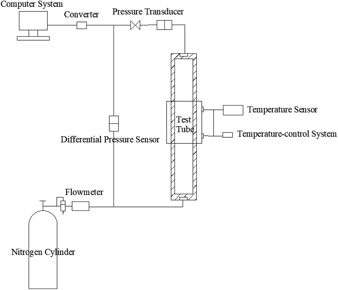
Figure 1: DFC-0806 oil well cement weight loss tester
A set of cement slurry systems in the central Sichuan area was selected to carry out a pressure loss evaluation experiment for cement slurry. The cement slurry formulation was as follows: 570 g cement G from Sichuan + 260 g hematite + 170 g silica fume + 3% SD77 + 0.3% SD35 + 3.5% SD130 + 0.3% SD210.
(1) The preparatory work before the experiment: ① Connect and start the computer test program to make the computer enter a state waiting for the start of the test. ② The tightness of the test tube and each pipeline is checked. ③ The temperature program of warm-up period is edited.
(2) The preparation process for the cement slurry: ① when the experimental temperature is lower than 90°C, the cement slurry is configured in accordance with the GB/T 19139 experimental method. The preheating temperature is the same as the test temperature. After entering the constant temperature section, the sample is poured into a weight loss test tube. ② When the experimental temperature is higher than 90°C, the preheating temperature is set to 90°C first, and the cement slurry is modulated to 90°C in atmospheric pressure or pressurized thickener according to the experimental method of GB/T 19139. Then, the cement slurry is poured into a preheated weight loss test tube and the heating program is re-edited before starting the test.
(3) Set the temperature and pressure program through the control panel, and ensure that all valves on the panel are closed.
(4) Preheated cement slurry in the thickener is injected into the test tube from above the weight loss test tube, and the experiment is started.
(5) The the test pressure control valve is adjusted to the test pressure, and then the test pressure is opened.
(6) Check whether the pressure value and pressure difference on your computer are normal, click the run button on the panel.
(7) Real-time monitoring of experimental pressure and pressure loss. After the initial setting of the cement slurry, the experimental instrument will automatically stop running. The real-time data and curves transmitted are saved to the computer system.
When the static gel strength of cement slurry develops to 48 Pa, the cement slurry enters the transition stage. When the static cementing strength of cement slurry develops to 48 Pa, the cement slurry enters the transition stage. When the static gel strength of cement slurry develops to 240 Pa, gas migration can be well suppressed [12,13]. Therefore, we call the time when the static gel strength of cement slurry develops from 48 Pa to 240 Pa as the transition time of static gel strength development. Liu and other scholars [9,14] believe that the transition time of static gel strength development is the dangerous time of gas channeling. Shortening the transition time of static gel strength development can effectively limit the gas channeling distance and reduce the harm of gas channeling. Similarly, for the same cement slurry system, there is also a phenomenon of cement slurry weight loss. In this process, the time when the cement slurry may cause gas channeling due to weight loss is called ‘weight loss dangerous transition time.’ We further discussed the factors affecting the weight loss pressure and the weight loss risk transition time.
The weight loss pressure evaluation experiment was carried out for the experimental cement slurry system under the conditions of experimental temperatures of 30°C, 60°C, 90°C, 120°C and 150°C and pressures of 6 MPa. By observing the weight loss law for cement slurry at different temperatures, it is proven that it is necessary for cement slurry to optimize the dosage of additive at high temperature. The experimental results are shown in Fig. 2.
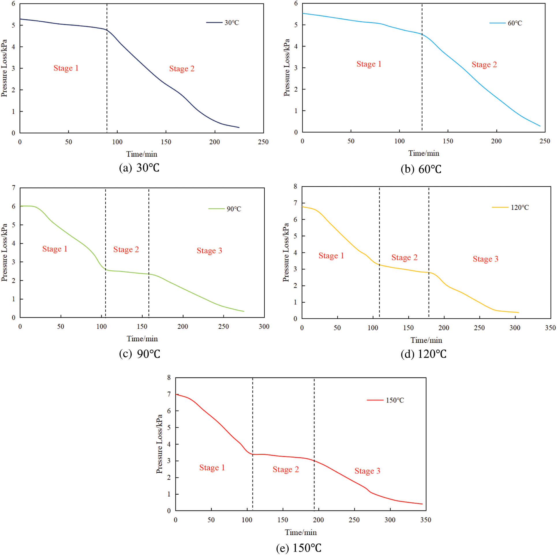
Figure 2: Curve charts of relationship between pressure loss and temperature
By evaluating the weight loss pressure of the cement slurry at different temperatures, it can be found that: (1) At temperatures of 30°C and 60°C, the weight loss curve for the cement slurry system showed ‘two-stage’ process. First, with the rapid development of the gel strength, the fluid column pressure shows a linear downward trend, and the cement slurry shows a gelling weight loss. Subsequently, with the gradual development of the cement slurry jelling structure, the pressure transmission capacity is limited until the fluid column pressure drops to the clear water column pressure. (2) At temperatures of 90°C, 120°C and 150°C, the weight loss curve of the cement slurry system showed a ‘three-stage’ process. First, the thixotropic or gel structure of cement slurry development is not obvious, and the liquid column pressure decreases significantly, resulting in sedimentation weight loss and poor cement slurry stability. Subsequently, the hydration of the cement slurry enters the induction period, for which the gelation strength develops rapidly and gelation weight loss occurs. Finally, when the induction period ends, the gel structure gradually develops completely, and the cement slurry continues to hydrate until the liquid column pressure drops to the clear water column pressure. (3) Better stability of cement slurry at 30°C and 60°C. The dangerous transition time for the cement slurry at 90°C is 68 min (108~175 min). The dangerous transition time for the cement slurry at 120°C is 80 min (105~185 min). The dangerous transition time for the cement slurry at 150°C is 98 min (105~203 min).
Therefore, with increasing temperature, the dangerous transition time for the cement slurry increases, and the anti-channeling performance of the cement slurry worsens [15]. Moreover, under high temperature conditions, the stability and anti-channeling performance of the experimental cement slurry system cannot meet the requirements. Through a large number of investigations, it can be found that retarder and fluid loss additive have the greatest impact on the change of pressure loss during the cement slurry setting at high temperature. To ensure that the basic performance and key performance of cement slurry remain unchanged, we consider optimizing the anti-channeling performance from the perspective of adjusting the dosage of retarder and fluid loss additive, and then obtain the cement slurry additive dosage formulation system with better anti-channeling performance.
3.2 The Influence of Retarder Dosage
By studying the influence of retarder dosage on the pressure loss of the cement slurry, and evaluating the anti-channeling performance of the cement slurry under different amounts through the weight loss curve, the best retarder dosage is finally selected.
The polyme retarder SD210 has good high-temperature resistance. It can inhibit the hydration rate of cement slurry at high temperature, effectively prolong the thickening time for the cement slurry, and adapt to cementing operations in a high-temperature environment. Under the premise of meeting the requirements of construction thickening time, the super retarding problem of top cement slurry caused by the long sealing section can be well solved [16]. Under the temperature and pressure conditions of 150°C and 6 MPa, respectively, the weight loss test experiment was carried out using the experimental cement slurry system with different retarder SD210 dosages. The experimental results are shown in Fig. 3. For a high-temperature environment, the dosage of retarder has an obvious influence on pressure loss. Under the premise of ensuring the thickening time, the cement slurry with 0.2% retarder shows the shortest gelation time and the best anti-channeling performance. It can effectively control the gas channeling distance and reduce the gas channeling hazards.
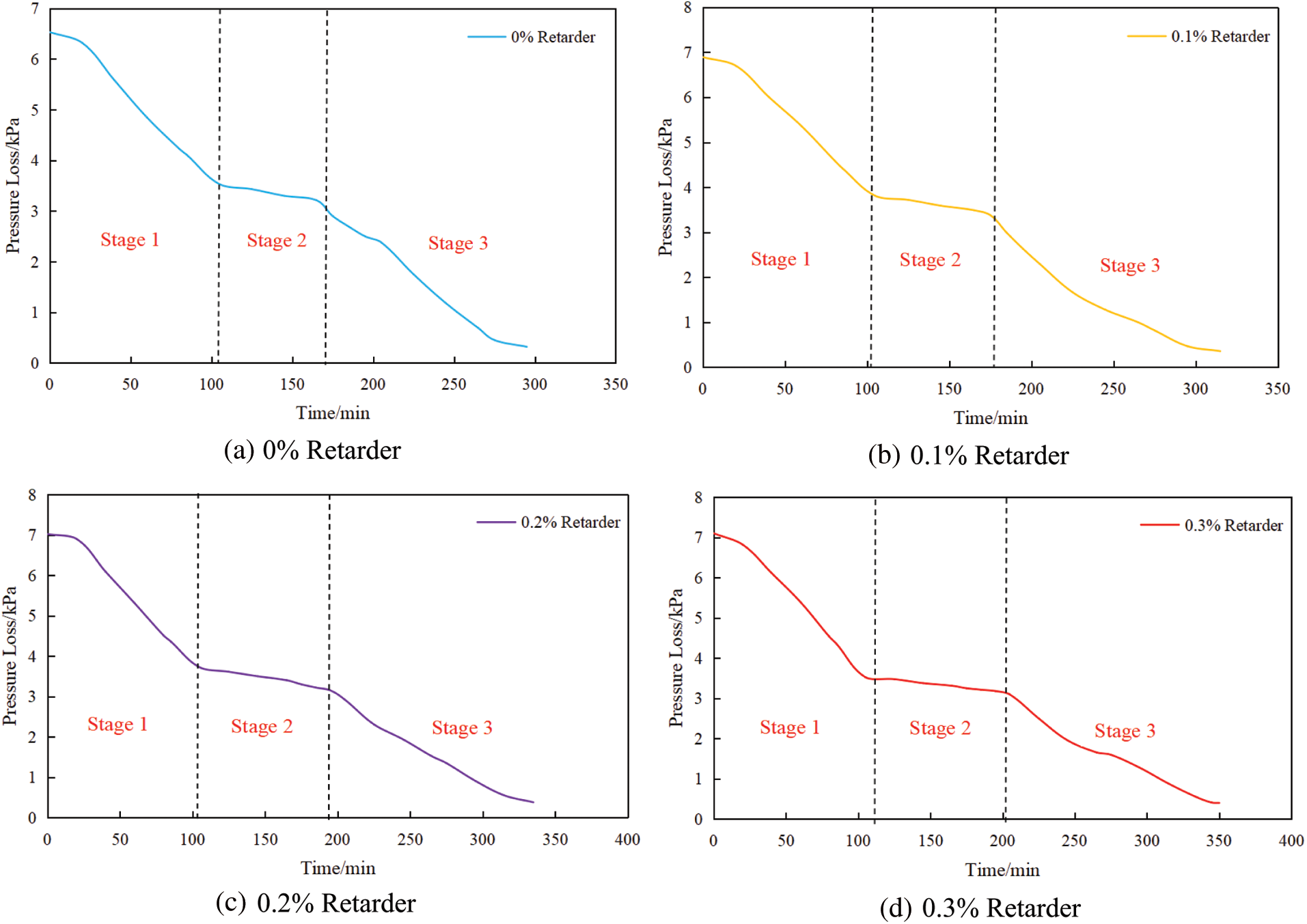
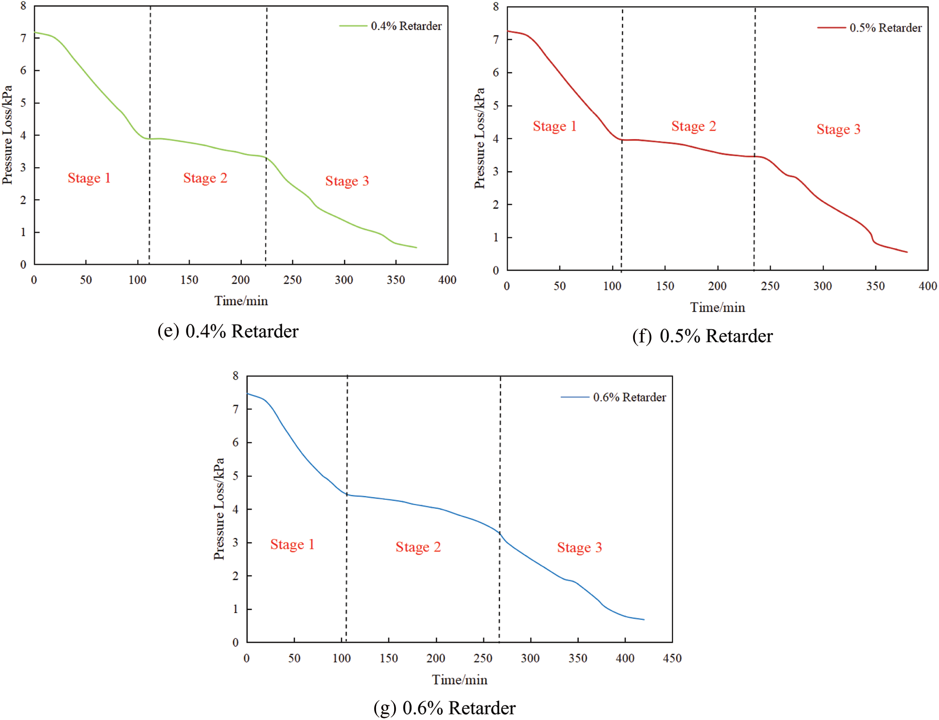
Figure 3: Weight loss curves of different retarder dosage
3.3 The Influence of Fluid Loss Additive Dosage
On the basis of the optimized dosage of the optimized retarder, the influence of the dosage of the fluid loss additive on the pressure loss of the cement slurry was studied. Finally, by evaluating the anti-channeling performance of the cement slurry under different dosages based on the weight loss curve, the best cement slurry dosage formula can be selected.
SD130 is a salt-resistant and high-temperature-resistant fluid loss additive. SD130 can still control water loss to less than 100 mL within 30 min at 140°C. With a further increase in dosage, the decreased degree of water loss decreases, which shows that its temperature resistance is good [17,18]. The good compatibility of the fluid loss additive SD130 and retarder SD210 can solve the problem of ‘super-retardation’ and early gas channeling caused by a large temperature difference. Under the conditions of 150°C and 6 MPa, the weight loss test experiment was carried out using the cement slurry system after the addition of the optimized retarder SD210. As shown in Fig. 4. By observing the weight loss curve, we find that: the dosage of fluid loss additive at high temperature has a significant effect on the weight loss pressure. With increasing amount of fluid loss additive, the gelling weight loss time of for the cement slurry becomes longer, and the weight loss becomes more serious. The cement slurry with 2.5% fluid loss additive shows the shortest weight loss time and the best channeling prevention performance.
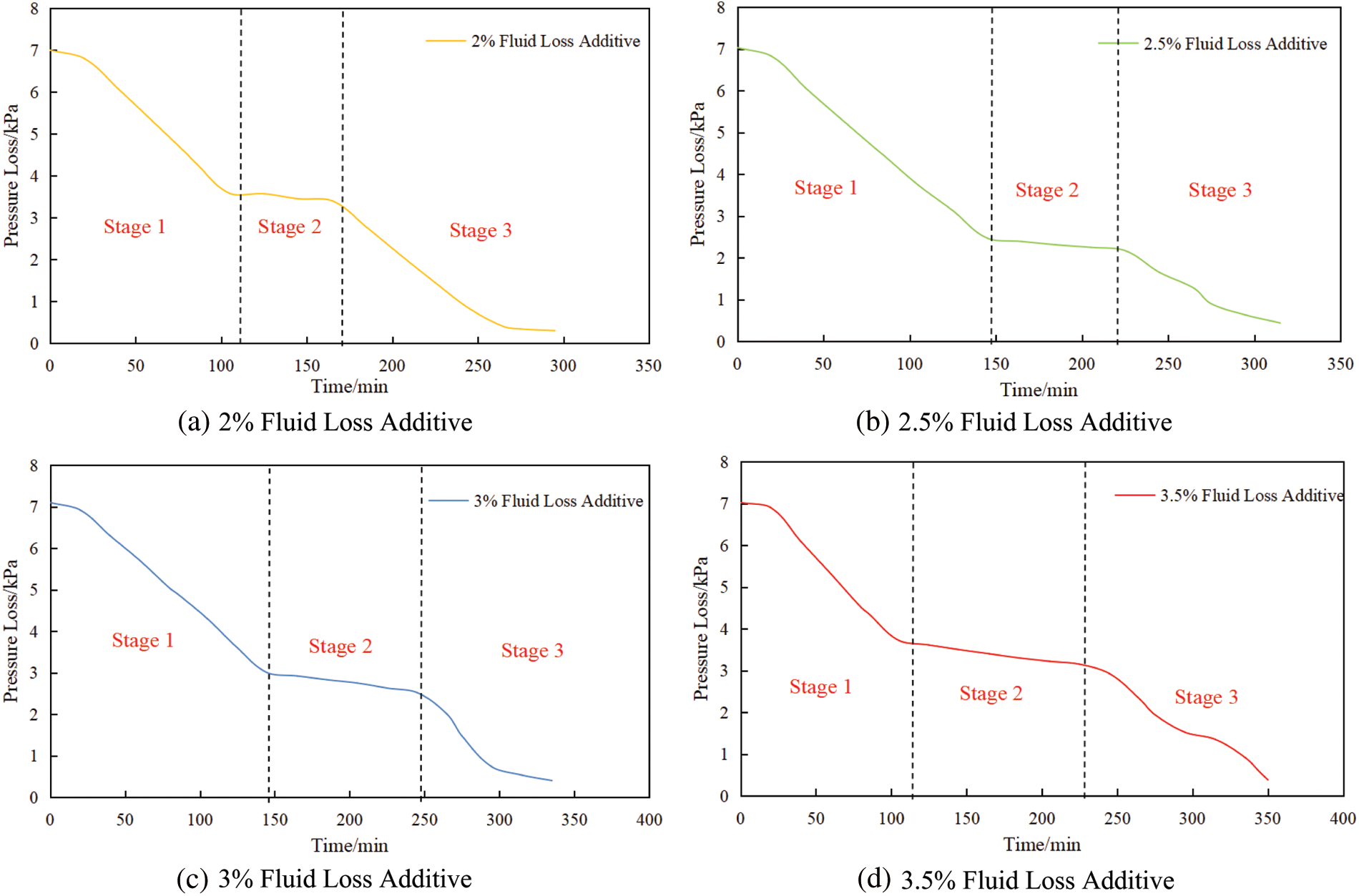

Figure 4: Weight loss curves of different fluid loss additive dosage
At the same time, in order to verify the reliability of the experiment, we use the existing mathematical model for calculation verification [19]. Based on the law of conservation of energy and the basic principles of hydrostatics, this model for calculating the pressure loss in waiting on cement (WOC) stage is derived in this research taking into comprehensive consideration the mutual action between the hydration reaction, temperature and pressure of cement slurry, as well as the complicated deep-water environment. Then, coupled calculation of the temperature, pressure and hydration kinetic models is made by using numerical difference method.
The meshing result is shown in Fig. 5. Considering that the borehole diameter is much smaller than the length of the wellbore, the model is designed axisymmetric to the center axis of the wellbore in the direction of the borehole diameter. Hence, the model is divided into non-uniform grids with equal space in the radial direction of wellbore and with equal logarithmic space in the stratum. The concrete solving method is as follows: input basic parameters, initial conditions and boundary conditions; mesh radially and axially and define initial nodes and step sizes; according to the current initial conditions, the temperature, pressure and hydration dynamics parameters at node are calculated and updated; according to the hydration kinetics model, the hydration kinetics parameters of cement slurry at node are calculated; combined with the established temperature field model, the transient temperature of node is calculated; combined with the established pressure field model, the transient pressure of node is calculated; the temperature and pressure calculation results are checked as per the test data to see whether they reach the required accuracy or not. If not, the calculation should be restarted from Step (3); if yes, the calculation is ended, and the calculation of the next time node is started; output the result.
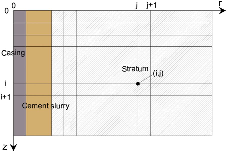
Figure 5: Schematic diagram of grid division
The results obtained by iteration of the calculation process are conducive to accurate prediction of the analytical solution of the wellbore temperature field, pressure field and pressure loss in WOC stage, which ensures the convergence and stability of the model. In order to improve the calculation accuracy and efficiency, by using the finite difference technology of the grid unit, pressure loss of cement slurry can be expressed as:
where
Based on the optimized cement slurry system dosage in this paper, field application was carried out in several wells. Under the premise of fully preparing for cementing and cementing construction, the cementing effect is good, which is consistent with the results of the indoor channeling performance evaluation experiment. In the following, A1 well and A2 well are taken as examples to discuss in detail the anti-channeling effect during well cementing.
4.1 Application of 177.8 + 184.2 mm Liner Cementing in the A1 Well
The A1 well is a rolling evaluation well in the Yushi-Hewanchang structural belt. Drill to 5716.00 m depth at the 3rd spud with a Φ215.9 mm drilling bit. To create conditions for the next drilling, the Φ177.8 mm + 184.15 composite liner is inserted to seal the 3178.00–5716.00 m section. The two-condensation interface is 3578.00 m, in which the rapid hardening cement slurry seals the well section of 3578.00 m–5716.00 m, and the retarded cement slurry seals the well section of 3178.00 m–3578.00 m. The main difficulty of this spud cementing operation is that there are nine oil and gas sections displayed in the Jia 2 ~ Deng 4 member for which 6 sections are gas invasion, oil and gas display is active, and it is difficult to prevent channeling. Before cementing construction, the wellbore is prepared, the regulation of drilling is strictly implemented, the performance of drilling fluid, and scientifically design the preflush system. The optimized cement slurry system is used to seal the open hole section, and the later construction is smooth, which effectively prevents gas channeling. The acoustic amplitude logging results show that the whole well is of high quality.
4.2 Application of 184.15 mm Liner Cementing in the A2 Well
The A2 well is a development well in the Leshan-Longnvsi Paleo-uplift. Drilling to 7481.00 m depth at the 3rd spud with Φ241.3 mm drilling bit. To create conditions for the next drilling, the Φ184.15 mm tail pipe is inserted to seal the 3690.00–7481.00 m section. in which the rapid hardening cement slurry seals the well section of 6200.00–7481.00 m, and the retarded cement slurry seals the well section of 4800.00–6200.00 m. The main difficulty for this spud cementing operation is the long cementing section and narrow pressure window, which lead to remarkable conflict between the prevention of circulation loss and channeling. The bottom temperature is high, so channeling easily occurs in the process of setting, which affects the cementing quality. The A2 well has a large temperature difference and the average geothermal gradient is approximately 2.06°C/100 m, which will have a significant impact on the weight loss of cement slurry. The optimized cement slurry system was used for the sealing operation, the construction process was smooth, and no gas leakage occurred after cementing. The results from acoustic amplitude logging interpretation show that the acceptance rate for cementing accounts is 73.1%, and the comprehensive evaluation is of high quality.
(1) Temperature is one of the important factors affecting the pressure loss of cement slurry. Too high of a temperature can result in the anti-channeling performance of cement slurry failing to meet the construction requirements. Therefore, in the design of cement slurry systems, the anti-channeling performance of cement slurry can be improved by optimizing the dosage of retarder and fluid loss additive.
(2) For a high temperature environment, the dosage of retarder has an obvious influence on pressure loss. With increasing amount of retarder, the weight loss time of cement slurry becomes longer. Under the premise for the ensuring thickening time, appropriate retarder dosage can effectively control gas channeling distance and reduce gas channeling hazard. The dosage of dehydrating agent at high temperature also has remarkable influence on pressure loss. With the increase of fluid loss additive, the longer weight loss time by gelling of cement slurry is, the more serious the weight loss is. The experimental results show that: without changing the basic performance of the cement slurry, the cement slurry system of 0.2% SD210 and 2.5% SD130 has the shortest gelation time and better anti-channeling performance.
(3) The successful field application of the optimized cement slurry system in multiple wells in A1 well and A2 well shows that the optimized cement slurry can well meet the anti-channeling requirements of the central Sichuan area. It provides a good reference for the optimization design of cement slurry system in large temperature difference and long cementing section wells.
Acknowledgement: The authors gratefully acknowledge the research project from “Research and test on optimization of calculation model for cementing engineering of high temperature and high pressure wells” (Grant No. CQCJ-2020-06).
Funding Statement: The authors received no specific funding for this study.
Conflicts of Interest: The authors declare that they have no conflicts of interest to report regarding the present study.
1. Liu, Y., Li, Y. Y. (2009). Study on the factors affecting the weight loss of cement slurry. Drilling Fluid & Completion Fluid, 26(5), 47–49. DOI 10.3969/j.issn.1001-5620.2009.05.016. [Google Scholar] [CrossRef]
2. Sabins, F. L., Tinsley, J. M., Sutton, D. L. (1982). Transition time of cement slurries between the fluid and set states. Society of Petroleum Engineers Journal, 22(6), 875–882. DOI 10.2118/9285-PA. [Google Scholar] [CrossRef]
3. Sabins, F. L., Sutton, D. L. (1986). The relationship of thickening time, gel strength, and compressive strength of oilwell cements. SPE Production Engineering, 1(2), 143–152. DOI 10.2118/11205-PA. [Google Scholar] [CrossRef]
4. Bu, Y., Mu, H., Jiang, L., Liu, W., Wei, X. et al. (2007). Modeling and laboratory studies of cement slurry weight loss. Drilling Fluid & Completion Fluid, 24(6), 52–54. DOI 10.3969/j.issn.1001-5620.2007.06.014. [Google Scholar] [CrossRef]
5. Beirute, R. M., Cheung, P. R. (1990). Method for selection of cement recipes to control fluid invasion after cementing. SPE Production Engineering, 5(4), 433–440. DOI 10.2118/19522-PA. [Google Scholar] [CrossRef]
6. Liu, Y., Chen, M., Shi, F. F., Li, Y. X., Xian, M. (2019). Study and application of a technology for evaluating pressure loss of cement plug. Drilling Fluid & Completion Fluid, 36(6), 749–753. DOI 10.3969/j.issn.1001-5620.2019.06.016. [Google Scholar] [CrossRef]
7. Zhu, H. J., Liu, A. P., An, S. H., Xu, J. X. (2012). A new method to evaluate the hydrostatic pressure of cement slurries. Oilfield Chemistry, 29(3), 353–356. DOI 10.19346/j.cnki.1000-4092.2012.03.023. [Google Scholar] [CrossRef]
8. Cheng, R., Yan, H., Wang, H., Zhang, F., Wang, S. (2012). Anti-channeling and anti-corrosion cementing technology for carbonate reservoirs in high temperature. Acta Petrolei Sinica, 33(S2), 181–188. DOI 10.7623/syxb2012S2019. [Google Scholar] [CrossRef]
9. Zhao, C., Zhang, C., Sun, H., Leng, Y., Fan, C. (2013). Development and application of the well cement retarder SD210L with a wide high temperature range. Natural Gas Industry, 33(1), 90–94. DOI 10.3787/j.issn.1000-0976.2013.01.015. [Google Scholar] [CrossRef]
10. Teng, X. Q., Liu, Y., Yang, C. X., Guo, X. Y., Li, N. (2011). Study and application of multifunction gas stop cement slurry. Journal of Southwest Petroleum University (Science & Technology Edition), 33(6), 151–154. DOI 10.3863/j.issn.1674-5086.2011.06.031. [Google Scholar] [CrossRef]
11. Carter, G., Slagle, K. (1972). A study of completion practices to minimize gas communication. Journal of Petroleum Technology, 24(9), 1170–1174. DOI 10.2118/3164-PA. [Google Scholar] [CrossRef]
12. Liu, P. Q., Sang, L., Xie, S., Gao, Y., Zhang, J. et al. (2019). Analysis of the anti-gas channeling effect and weight loss law of styrene-acrylic latex cement slurry. Petroleum Drilling Techniques, 47(1), 52–58. DOI 10.11911/syztjs.2018141. [Google Scholar] [CrossRef]
13. Cheng, X., Liu, K., Li, Z., Guo, X. (2016). Structure and properties of oil well cement slurry during liquid-solid transition. Acta Petrolei Sinica, 37(10), 1287. DOI 10.7623/syxb201610009. [Google Scholar] [CrossRef]
14. Wilkins, R. P., Free, D. (1989). A new approach to the prediction of gas flow after cementing. SPE/IADC Drilling Conference. OnePetro. DOI 10.2118/18622-MS. [Google Scholar] [CrossRef]
15. Zou, P., Huang, Z., Tong, Y., Tan, L., Li, R. et al. (2022). Experimental evaluation of the mechanical properties of cement sheath under high-temperature conditions. Fluid Dynamics & Materials Processing, 18(3), 689–699. DOI 10.32604/fdmp.2022.019470. [Google Scholar] [CrossRef]
16. Yong, M., Rong, C. M., Yang, G., Qing, S., Li, L. (2007). How to evaluate the effect of mud cake on cement bond quality of second interface? SPE/IADC Middle East Drilling and Technology Conference. OnePetro. DOI 10.2118/108240-ms. [Google Scholar] [CrossRef]
17. Backe, K. R., Lile, O. B., Lyomov, S. K. (2001). Characterizing curing cement slurries by electrical conductivity. SPE Drilling & Completion, 16(4), 201–207. DOI 10.2118/74694-PA. [Google Scholar] [CrossRef]
18. Moon, J., Wang, S. (1999). Acoustic method for determining the static gel strength of slurries. SPE Rocky Mountain Regional Meeting. DOI 10.2118/55650-ms. [Google Scholar] [CrossRef]
19. Lv, K., Huang, H., Zhong, X., Tong, Y., Ling, X. et al. (2021). A prediction model of pressure loss of cement slurry in deep-water HTHP directional wells. Energies, 14(23), 8180. DOI 10.3390/en14238180. [Google Scholar] [CrossRef]
 | This work is licensed under a Creative Commons Attribution 4.0 International License, which permits unrestricted use, distribution, and reproduction in any medium, provided the original work is properly cited. |