| Fluid Dynamics & Materials Processing |
DOI: 10.32604/fdmp.2022.019534
ARTICLE
Experimental Investigation of Two-Phase Flow Maldistribution in Plate Heat Exchangers
1Shakarim University of Semey, Semey City, 070000, Kazakhstan
2Plekhanov Russian University of Economics, Moscow, 117997, Russia
3National Research Mordovia State University, Mordovia, 430005, Russia
4Bauman Moscow State Technical University, Moscow Region, Mytischi, 105005, Russia
5K.G. Razumovsky Moscow State University of Technologies and Management (The First Cossack University), Moscow, 119991, Russia
6Financial University Under the Government of the Russian Federation, Moscow, 125993, Russia
7Russian State Agrarian University–Moscow Timiryazev Agricultural Academy, Moscow, 127550, Russia
*Corresponding Author: Zhaiyk Tokhtarov. Email: goz.mr@yahoo.com
Received: 28 September 2021; Accepted: 18 December 2021
Abstract: After conducting a critical survey of the different categories of existing heat exchangers, the results of several experiments about the behaviour of a two-phase current in an open channel are reported. The results confirm the complexity of the problems induced in heat exchangers by flow maldistribution, especially when two-phase flows are considered in multi-channel systems. It is shown that severe misalignment of heat exchangers can lead to a loss of economic performance of more than 25%. Improper distribution of fluid flow causes longer fluid coils to form, and the liquid cochlea can eventually occupy a large space, thereby reducing heat transfer and disrupting the considered biphasic system. The use of a small diameter distribution pipe with properly spaced outlet holes seems to be a promising approach to fix many of these issues. It is found that the current distribution in the channels, in addition to the header pressure distribution, also depends on factors such as the geometry and the initial flow regime in the header.
Keywords: Maldistribution; heat exchangers; two phase; open channel
Heat exchangers are almost the most widely used members in chemical processes and can be seen in most industrial units. They are devices that allow the transfer of thermal energy between two or more fluids at different temperatures. This operation can be performed between liquid-liquid, gas-gas or gas-liquid [1]. Heat exchangers are used to cooling hot fluid or to heat the fluid to a lower temperature, or both [2,3].
Heat exchangers are used in a wide range of applications. These applications include power plants, refineries, petrochemical industries, manufacturing industries, process industries, food and pharmaceutical industries, metal smelting industries, heating, air conditioning, refrigeration systems and space applications [4–6]. Heat exchangers in various devices such as boilers, steam generators, condensers, evaporators, evaporators, cooling towers, preheaters, fan coils, oil coolers and heaters, radiators, furnaces, etc. are widely used. In recent years, the use of compact heat exchangers for single and two-phase applications has increased in the process industry [7–9]. In the thermodynamic design and analysis of plate heat exchangers, it is generally assumed that both liquids are evenly distributed across all parallel passages throughout the core of the transducer. Plate heat exchangers are primarily used in liquid-to-liquid heat transfer tasks [7]. Thus, performance in single-phase applications has been documented in the open literature to such an extent that it is possible to reliably design and rank euro calculations. In such experiments, many combinations are possible for each flow, and the flow configuration must be carefully selected to avoid severe current distribution and achieve better performance. Heat exchangers can be classified into different aspects:
– Based on the type and contact surface of hot and cold fluid
– Based on the direction of cold and hot fluid flow
– Based on the heat transfer mechanism between hot and cold fluids
– Based on the mechanical structure and structure of the converters
In [10], Li et al. proposed an experimental and numerical investigation of the single-phase flow distribution in the brazed plate heat exchangers. Their results indicated that in a U-type brazed plate heat exchanger, the channel flow rate first increases for the channels nearby to the heat exchanger entrance since the sudden expansion of flow in the inlet part. For the other channels, the flow rate reduces with the distance away from the inlet/outlets. In [11], Zhang et al. reviewed on mal-distribution and hysteresis phenomena of gas–liquid and gas–solid two-phase flow in parallel channels, they found that multiple steady states can be encountered in parallel channels which leads to the occurrence of flow mal-distribution and flow hysteresis in parallel channels. In [12,13], Esposito et al. investigated the effect of flow maldistribution in cross-flow heat exchangers. In [14–16], Nasrabadi et al. characterized the maldistribution phenomenon in plate heat exchangers while [13,14] studied maldistribution of refrigerant flow in fin-tube heat exchangers used for air-conditioning equipment. Many industries are involved in the design of various types of heat exchangers, and there are also several courses offered in colleges and universities under various names in the design of heat exchangers. Converter calculations are a long and sometimes tedious task. For example, designing a converter for a particular operation requires a lot of guesswork that can be used to find the right size of a converter according to standards [17]. But with the use of computer programs, all these calculations are performed by the computer, and the designer only has to enter the operating conditions and the properties of the fluids present in operation to design. These include Aspen B-jac and HTFS software. These applications include programs that have the ability to perform such calculations. Many articles [18,19] have dealt with the destructive effects of current distribution on the performance of heat exchangers, but the mother of this article wants to address the effects of distribution and placement of heat exchangers in two-phase current in open channels.
The experiments were performed in a horizontal channel with a rectangular cross-section with dimensions of 5 × 10 cm2 (hydraulic equivalent diameter/67.6 cm) and a length of 36 m (length equivalent to 5400) made of Plexiglas 10. The channel is located on a number of metal supports with adjustable angle and non-conductive heat. For this research, the heat cycle of the two-pipe converter has been used. The inner tube of the copper converter is 12 mm in diameter and 1 mm thick, with a heat exchange length of 70 cm.
Its shell diameter is 8.50 mm. The current inside the converter of non-directional valves is considered. The plate converter is a small and customized example of a conventional home radiator with dimensions of 40 and 60 cm in height and length, respectively, which exchanges heat with the surrounding environment [14].
The fluid used in modelling is water. Heat transfer in frame and plate heat exchangers is simulated in this paper in the form of six models. The transient response of the heat exchangers is investigated by applying a step input to the system. In the initial heat-stable conditions of the converter, the temperature of all points is assumed to be equal to 300 K. The step input is entered towards the heat exchanger and is simulated as a step in time 0. 1 s reaches its peak, 350 K, along the path of a third-degree curve [15].
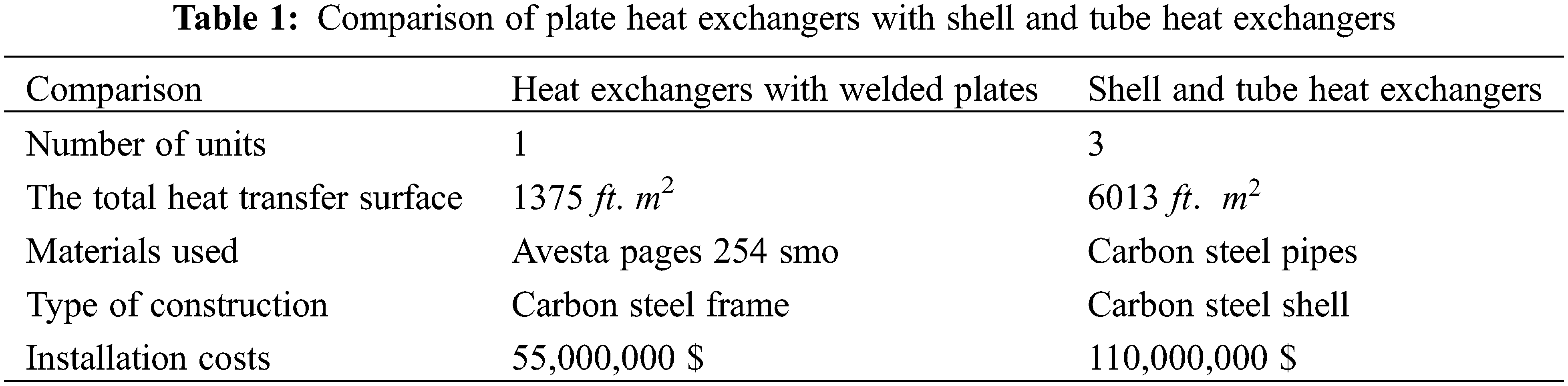
As liquid and gas phases flow through the tube, various flow patterns are created. The interactions between the phases give rise to these different flow patterns. The main factors influencing the flow pattern inside the pipe include fluid parameters such as flow rate and flow direction of each phase of fluid characteristics and geometric parameters such as pipe diameter, pipe slope, pipe geometry and others [16]. Momental transfer between two phases, heat transfer and mass transfer in two-phase flow is strongly influenced by current patterns. Therefore, it is necessary to study the flow patterns in order to create proper performance and safety during the process and perform operations in various industries such as refineries, petrochemicals, etc. [17]. Given the above, it is natural that many studies have been conducted on biphasic flow patterns so far; however, most studies have focused on biphasic currents. In this experiment, we first compared the two plate heat exchangers with the shell and tube heat exchangers, according to Table 1.
Then we use the following equations to investigate how heat is transferred between the converters and how the exchangers are distributed in the open channel during the two phases. From one point of view, the studies performed on pipes can be classified into two categories of experiments performed on large-scale and small-scale pipes [18,19]. Various criteria are provided for our pipe scaling. We consider small-scale pipes that meet condition 1.
In relation (1), d is the inner diameter of the pipe, S is the surface tension coefficient between the two phases, g is the gravitational acceleration and Pi and Pg the density of the liquid and gas phases, respectively [20]. For phase Liquid water and air gas phase at ambient conditions (temperature 25°C and pressure 1 atmosphere) surface tension coefficient equal to 0.072 N/m, water density equal to 977 k/m3 and air density having a value of 1.184 kg/m3 Are, so the condition is d ≤ 5.15 cm; In other words, pipes with an inner diameter of less than 50 mm are small pipes and pipes with a diameter of more than 50 mm are large pipes [21].
The heat transfer coefficient in a two-pipe heat exchanger is calculated based on the energy balance:
which is the index related to the flow of cold water inside the shell and nf is related to the nanofluid being tested. ΔQ = Qnf − Qc. The amount of heat lost is considered to be about 20% to 25% for a two-pipe heat exchanger. On the other hand, we have displacement to transfer heat:
U is the overall heat transfer coefficient and for bladeless tube heating models, ignoring the transducer deposition, based on the outer surface of the tube, A, by definition, is:
By calculating h from the following equation for turbulent flow within the shell [22].
where D is the equivalent diameter of the converter shell:
Putting it in the above equation is the only unknown h that is obtained by solving the equation. Nu is then also calculated. The following equation was used to calculate the transfer heat transfer coefficient in the plate converter:
where hnf is the heat transfer coefficient of the nanofluid, A is the heat exchange rate of the medium with the environment, Tamb is the ambient temperature and Tw is the temperature of the transducer, and is the amount of heat. The loss is calculated as follows:
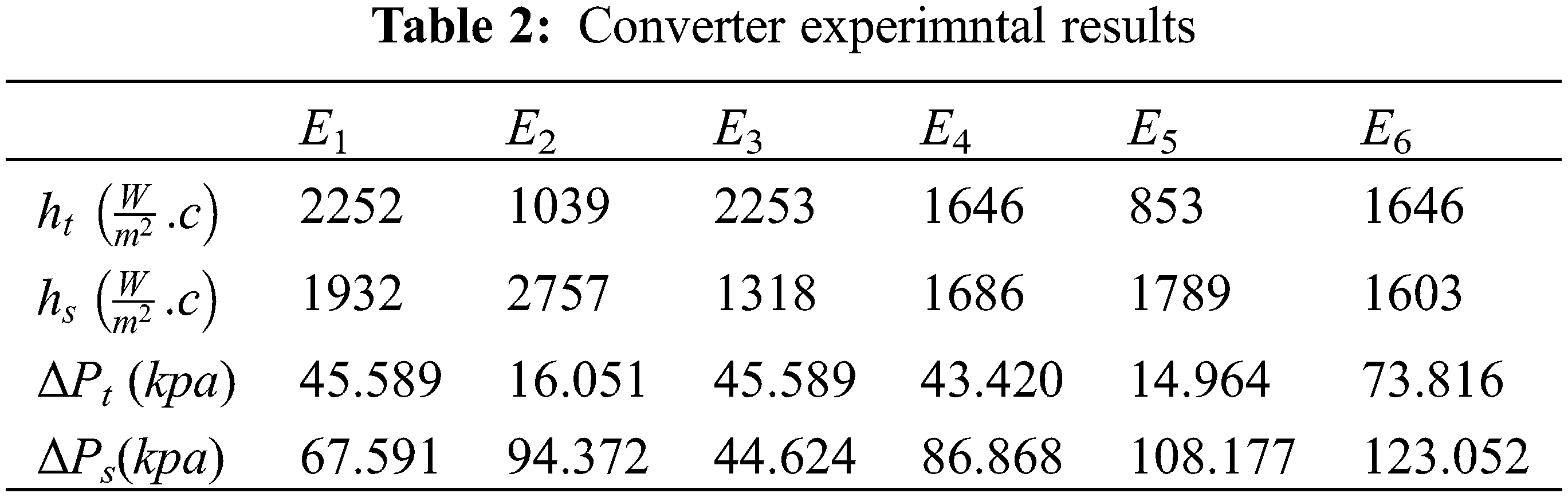
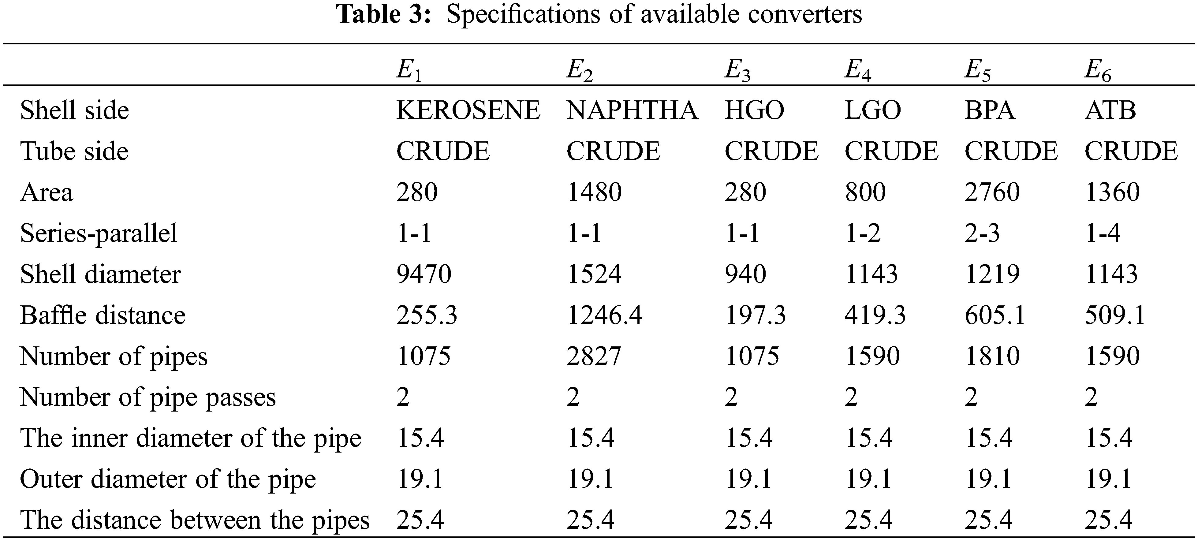
The present paper reports the results of experiments performed on a horizontal two-phase flow in an open channel. According to the above, it can be seen that each of the plate heat exchangers, according to the structural characteristics, the number of fluids passing through, the type of flow arrangement, the amount of surface compaction and the type of heat transfer process, can be used for specific applications. The results are summarized in Tables 2 and 3.
Based on these data, targeting can be done using heat transfer improvement methods. In this case, as presented in Table 4, only the use of a torsion tube converter can be done which is in agreement with [23].

In this study, by evaluating the effect of increasing the capacity on the performance of heat exchangers, a range was provided to compensate for the additional level required to increase the capacity using thermal improvement methods. By modifying the distribution of the converters in the open channel, we compare the obtained results with the previous conditions:
The additional level required between each converter for better performance and more economical distribution of converters in the channel is shown in Table 5.

It can be seen that the temperature distribution is qualitatively similar to the flow distribution, and the highest temperature occurs in the central area of the heat exchanger, which is in agreement with [24]. However, it should be noted that temperature non-uniformity is more pronounced than current. Also, the uniformity of temperature and flow in heat exchangers can be observed according to the following Table 6:

Fig. 1 shows the distribution in a Kapton heat exchanger. Fig. 1a below shows the two-phase output state of the evaporator at a sufficiently low vapour fraction. This situation inhibits differentiation, and the distribution looks great. Distribution problems are evident in the Fig. 1b, with lower flow rates and higher evaporation temperatures [25,26]. This two-phase mixture strikes the opposite wall of the heat exchanger and is sprayed into the channels located in the radius.

Figure 1: Two infrared images of distribution in the heat exchanger
Obtaining a uniform two-phase distribution in two-tube feed headers is very difficult given the laboratory conditions of this experiment. For horizontal headers, the separation of gravity of the liquid phases exacerbates the problem [27,28]. This problem exists in split headers, which may be at the top or bottom of the heat exchanger. Melted evaporators typically use horizontal headers to facilitate condensate discharge. Although projecting the end of the tube and the middle veins can improve the flow distribution, they are not enough. The effect of the heat exchanger on flow temperature can be seen in Fig. 2.

Figure 2: The increase in temperature of the cold water inlet of the heat exchanger depends on the flow rate
In order to investigate the effects of the Reynolds number on the flow patern, Fig. 3 shows the effect of Reynolds number on the intensity of maldistribution. The intensity of the flow maldistribution grows with increasing Re The differences between the various reynolds are related to an inconsistent pressure drop balance. The pressure loss in the header of the flow is too high in relation to the pressure drop in the channels, and the flow chooses the least energy through the first few channels.

Figure 3: Effect of reynolds number on the maldistribution in the channels of heat exchanger
The program was applied to three two-phase reciprocating heat exchangers and three counter heat exchangers, both of which work with water. One-dimensional simulation of a simple two-phase flow was made for an electrically heated water evaporator. The results of heat transfer (temperature) are consistent with the experimental findings. More deviations are seen for pressure drop, which is, for example, much more sensitive to the precision of the channel geometry or sediment in the channel wall [29].
In other words, the phenomenon is similar to the distribution of two-phase currents from a main vertical to two horizontal branches that are connected in parallel. According to Lee, the amount of liquid flow through the second branch is almost less than the first branch with a fraction of about 0.5–0.7 and the trend was the same for three different branches (canal) distances. The reason is that the liquid film is easily separated at the entrance to the first junction (i.e., at the entrance of the first branch) and the remaining amount of liquid film reaches the next junction. With the distance of the smaller branches, the liquid film reaches the next joint without redistribution to have a uniform thickness, and the rate of liquid division to the second branch is reduced.
A review of the literature on the distribution of two-phase currents in parallel channels showed that much research had been done in the last decade. Most studies were based on experimental analysis. It is clear that there are problems in comparing the experiments of incorrect distribution of heat exchangers in two-phase flow in open channels with the channels reported in other experiments and articles. In fact, a large amount of data is obtained using different combinations and different operating conditions (total mass flow rate, gas quality, liquid, etc.) and geometric settings (header shape and dimensions, feed pipe, number of channels, feed pipe position). It was mentioned that several of these parameters play an important role in the incorrect distribution of converters during two-phase flow. As a result, the data obtained in studies conducted in different laboratories show significant variation. Operating conditions also play an important role in the two-phase current distribution. For a given device geometry, the two-phase flow pattern is also affected by the header and channel direction in relation to gravity, as well as the two-phase flow direction. Total mass flow velocity and gas quality lead to a given two-phase flow pattern in the feed pipe. In addition to the proper distribution of converters, geometric corrections can also be used to improve heat transfer during two-phase open channels. However, these changes may cause problems, for example, a higher pressure drop. In this regard, further experiments are still needed to examine other possible effects, such as header shape, channel shape, and fluid properties, as well as to better understand the importance of the feed pipe condition and outlet conditions. Based on the experimental results, the efficiency of the heat exchanger was also calculated for different headers. The change in the efficiency of the heat exchanger can be plotted as a function of the flow non-uniformity parameter. Temperature uniformity is more pronounced than current and leads to varying degrees of loss of heat exchanger effect. Improvements in header configuration can effectively increase the performance of plate heat exchangers by controlling flow unevenness. The degree of temperature non-uniformity can be reduced from 0.939 to 0.702 using the improved header. The correlation between the flow non-uniformity parameter and the heat exchanger efficiency drop was also obtained in the experimental study. Analytical and numerical models can be better developed based on available experimental data and two-phase flow models in T-joints and can be further improved by considering landing and Weber numbers. In order to gain a better understanding of the phenomenon of biphasic currents occurring, and the incorrect distribution of transducers in parallel channels, the development of new approaches is needed.
The present paper reports the results of several experiments performed on a two-phase current in an open channel. The results confirm the complexity of the two-phase current distribution phenomenon and the difficulty of how the converters are distributed in a multi-channel channel system. This study shows that severe misalignment of heat exchangers can lead to a loss of economic performance of more than 25%. Improper distribution of fluid flow causes longer fluid coils to form, and the liquid cochlea can eventually occupy the entire canal branch, reducing heat transfer and disrupting the biphasic system. The use of a small diameter distribution pipe (or similar) with outlet holes with a small distance along it seems to be a good concept for achieving a good flow distribution. It is found that the current distribution in the channels, in addition to the header pressure distribution, also depends on factors such as the geometry and the initial flow regime in the header.
Funding Statement: The authors received no specific funding for this study.
Conflicts of Interest: The authors declare that they have no conflicts of interest to report regarding the present study
1. Shabgah, A. G., Qasim, M. T., Mostafavi, S. M., Zekiy, A. O., Ezzatifar, F. et al. (2021). CXC chemokine ligand 16: A swiss army knife chemokine in cancer. Expert Reviews in Molecular Medicine, 21(23), e4. DOI 10.1017/erm.2021.7. [Google Scholar] [CrossRef]
2. Yang, S., Jasim, S. A., Bokov, D., Chupradit, S., Nakhjiri, A. T. et al. (2021). Membrane distillation technology for molecular separation: A review on the fouling, wetting and transport phenomena. Journal of Molecular Liquids, 349, 118115. DOI 10.1016/j.molliq.2021.118115. [Google Scholar] [CrossRef]
3. Pustokhina, I., Seraj, A., Hafsan, H., Mostafavi, S. M., Alizadeh, S. M. (2021). Developing a robust model based on the gaussian process regression approach to predict biodiesel properties. International Journal of Chemical Engineering, 2021(1), 1–12. DOI 10.1155/2021/5650499. [Google Scholar] [CrossRef]
4. Mahmoodi-k, M., Montazeri-Gh, M., Madanipour, V. (2021). Simultaneous multi-objective optimization of a PHEV power management system and component sizing in real world traffic condition. Energy, 233, 121111. DOI 10.1016/j.energy.2021.121111. [Google Scholar] [CrossRef]
5. Fu, C., Rahmani, A., Suksatan, W., Alizadeh, S. M., Zarringhalam, M. et al. (2021). Comprehensive investigations of mixed convection of Fe–ethylene-glycol nanofluid inside an enclosure with different obstacles using lattice boltzmann method. Scientific Reports, 11(1), 1–16. DOI 10.1038/s41598-021-00038-7. [Google Scholar] [CrossRef]
6. Taitel, Y., Dukler, A. E. (1976). A model for predicting flow regime transitions in horizontal and near horizontal gas-liquid flow. AIChE Journal, 22(1), 47–55. DOI 10.1002/(ISSN)1547-5905. [Google Scholar] [CrossRef]
7. Du, X., Wu, X., Li, R., Cheng, R. (2019). Numerical simulation and optimization of a mid-temperature heat pipe exchanger. Fluid Dynamics & Materials Processing, 15(1), 77–87. DOI 10.32604/fdmp.2019.05949. [Google Scholar] [CrossRef]
8. Arslan, E., Koşan, M., Aktaş, M., Dolgun, E. C. (2020). Designing of a new type air-water cooled photovoltaic collector. TehniČki Glasnik, 14(1), 41–45. DOI 10.31803/tg-20190227095246. [Google Scholar] [CrossRef]
9. Jia, Y., Wang, J., Shang, L. (2020). Optimization of a heat exchanger using an ARM core intelligent algorithm. Fluid Dynamics & Materials Processing, 16(5), 871–881. DOI 10.32604/fdmp.2020.09957. [Google Scholar] [CrossRef]
10. Li, W., Hrnjak, P. (2021). Single-phase flow distribution in plate heat exchangers: Experiments and models. International Journal of Refrigeration, 126, 45–56. DOI 10.1016/j.ijrefrig.2021.01.026. [Google Scholar] [CrossRef]
11. Zhang, L., Hu, G., Bi, X. T. (2022). Two-phase flow in parallel channels: Mal-distribution, hysteresis and mitigation strategies. Chemical Engineering Science, 247, 117044. DOI 10.1016/j.ces.2021.117044. [Google Scholar] [CrossRef]
12. Esposito, A., Lappa, M., Pagliara, R., Spada, G. (2022). A mixed radiative-convective technique for the calibration of heat flux sensors in hypersonic flow. Fluid Dynamics & Materials Processing, 18(2), 189–203. DOI 10.32604/fdmp.2022.019605. [Google Scholar] [CrossRef]
13. Jia, Y., Wang, J., Shang, L. (2020). Optimization of a heat exchanger using an ARM core intelligent algorithm. Fluid Dynamics & Materials Processing, 16(5), 871–882. DOI 10.32604/fdmp.2020.09957. [Google Scholar] [CrossRef]
14. Nasrabadi, M., Sevbitov, A. V., Maleki, V. A., Akbar, N., Javanshir, I. (2022). Passive fluid-induced vibration control of viscoelastic cylinder using nonlinear energy sink. Marine Structures, 81, 103116. DOI 10.1016/j.marstruc.2021.103116. [Google Scholar] [CrossRef]
15. Wu, J., Wang, Y. (2021). Liquid blockage and flow maldistribution of two-phase flow in two parallel thin micro-channels. Applied Thermal Engineering, 182, 116127. DOI 10.1016/j.applthermaleng.2020.116127. [Google Scholar] [CrossRef]
16. Hoseini, M., Haghtalab, A., Navid Family, M. (2020). Elongational behavior of silica nanoparticle-filled low-density polyethylene/polylactic acid blends and their morphology. Rheologica Acta, 59, 621–630. DOI 10.1007/s00397-020-01225-5. [Google Scholar] [CrossRef]
17. Xia, G., Zhuang, D., Ding, G., Lu, J., Han, W. et al. (2021). A distributed parameter model for multi-row separated heat pipe with micro-channel heat exchangers. Applied Thermal Engineering, 182, 116113. DOI 10.1016/j.applthermaleng.2020.116113. [Google Scholar] [CrossRef]
18. Mahvi, A. J., Garimella, S. (2019). Two-phase flow distribution of saturated refrigerants in microchannel heat exchanger headers. International Journal of Refrigeration, 104, 84–94. DOI 10.1016/j.ijrefrig.2019.04.026. [Google Scholar] [CrossRef]
19. Zhang, Z., Mehendale, S., Lv, S., Yuan, H., Tian, J. (2021). The influence of header design on two-phase flow distribution in plate-fin heat exchangers. Journal of Thermal Science and Engineering Applications, 13(2), 21013. DOI 10.1115/1.4047522. [Google Scholar] [CrossRef]
20. Zhang, Z., Mehendale, S., Tian, J., Li, Y. (2017). Experimental investigation of two-phase flow distribution in plate-fin heat exchangers. Chemical Engineering Research and Design, 120, 34–46. DOI 10.1016/j.cherd.2017.02.003. [Google Scholar] [CrossRef]
21. Brenk, A., Pluszka, P., Malecha, Z. (2018). Numerical study of flow maldistribution in multi-plate heat exchangers based on robust 2D model. Energies, 11(11), 3121. DOI 10.3390/en11113121. [Google Scholar] [CrossRef]
22. Van Oevelen, T., Weibel, J. A., Garimella, S. V. (2018). The effect of lateral thermal coupling between parallel microchannels on two-phase flow distribution. International Journal of Heat and Mass Transfer, 124, 769–781. DOI 10.1016/j.ijheatmasstransfer.2018.03.073. [Google Scholar] [CrossRef]
23. Yuan, P., Jiang, G. B., He, Y. L., Tao, W. Q. (2016). Performance simulation of a two-phase flow distributor for plate-fin heat exchanger. Applied Thermal Engineering, 99, 1236–1245. DOI 10.1016/j.applthermaleng.2016.01.096. [Google Scholar] [CrossRef]
24. Nourdanesh, N., Ranjbar, F. (2022). Investigation on heat transfer performance of a novel active method heat sink to maximize the efficiency of thermal energy storage systems. Journal of Energy Storage, 45, 103779. DOI 10.1016/j.est.2021.103779. [Google Scholar] [CrossRef]
25. Zhang, T., Wen, J. T., Julius, A., Peles, Y., Jensen, M. K. (2011). Stability analysis and maldistribution control of two-phase flow in parallel evaporating channels. International Journal of Heat and Mass Transfer, 54(25–26), 5298–5305. DOI 10.1016/j.ijheatmasstransfer.2011.08.013. [Google Scholar] [CrossRef]
26. Zhang, Z., Mehendale, S., Tian, J., Li, Y. (2015). Fluid flow distribution and heat transfer in plate-fin heat exchangers. Heat Transfer Engineering, 36(9), 806–819. DOI 10.1080/01457632.2015.963411. [Google Scholar] [CrossRef]
27. Ahmadizadeh, P., Mashadi, B., Lodaya, D. (2017). Energy management of a dual-mode power-split powertrain based on the pontryagin’s minimum principle. IET Intelligent Transport Systems, 11(9), 561–571. DOI 10.1049/iet-its.2016.0281. [Google Scholar] [CrossRef]
28. Mao, J. N., Chen, H. X., Jia, H., Wang, Y. Z., Hu, H. M. (2013). Effect of air-side flow maldistribution on thermal–hydraulic performance of the multi-louvered fin and tube heat exchanger. International Journal of Thermal Sciences, 73, 46–57. DOI 10.1016/j.ijthermalsci.2013.06.001. [Google Scholar] [CrossRef]
29. Yoon, S. H., Saneie, N., Kim, Y. J. (2014). Two-phase flow maldistribution in minichannel heat-sinks under non-uniform heating. International Journal of Heat and Mass Transfer, 78, 527–537. DOI 10.1016/j.ijheatmasstransfer.2014.07.013. [Google Scholar] [CrossRef]
 | This work is licensed under a Creative Commons Attribution 4.0 International License, which permits unrestricted use, distribution, and reproduction in any medium, provided the original work is properly cited. |