| Fluid Dynamics & Materials Processing |
DOI: 10.32604/fdmp.2022.019038
ARTICLE
Structural Design and Analysis of a Booster Arm Made of a Carbon Fiber Reinforced Epoxy Composite Material
Baoshan Power Supply Bureau of Yunnan Power Grid Co., Ltd., Baoshan, 67800, China
*Corresponding Author: Songhua Hu. Emails: timothy@stu.cpu.edu.cn, slx525@126.com
Received: 31 August 2021; Accepted: 10 January 2022
Abstract: An analysis of a booster arm made of a carbon fiber reinforced epoxy composite material is conducted by means of a finite element analysis method. The mechanical properties are also determined through stretching and compression performance tests. It is found that the surface treatment of the fibers causes the silane coupling agent to undergo a chemical reaction on the surface of the glass fiber. The used material succeeds in producing significant vibrations damping (vibration attenuation effect is superior to that obtained with conventional alloy materials).
Keywords: Study on the performance of carbon fiber; composite material; power arm structure; power arm
Carbon fiber reinforced composites serve as new lightweight structural materials, with high strength, high ratios, and other advantages, widely used in aerospace sectors [1]. Mechanical properties of carbon fiber reinforced composites can be changed by design, providing a degree of freedom to designers, and therefore often applied as a structural material to mechanical structures for damping suppression and accuracy control [2]. With the continuous expansion of the application range of the power arm, especially in the spatial field, the power resistance is moving towards efficient, low-cost, lightweight, and flexible, and its purpose is to improve the operation and flexibility of the boost arm. Sex, so the flexible helper arm has become the focus of current research.
However, the flexible helper arm is highly light, the stiffness is small, and the elastic deformation and mechanical vibration is very priorcted during exercise, which in turn affects its mechanical properties [3]. Bao et al. [4] analyzed that there is a significant difference between the output characteristics of the flexible auxiliary arm and the rigid auxiliary arm. Yang et al. [5] effectively improved the position accuracy of the flexible booster arm. Xue et al. [6] established a dynamic model of the space flexible auxiliary arm using harmonic gauges and analyzed its motion accuracy. At present, a lot of research has been done on the flexible vibration of power arm, but the algorithm is more complicated [7]. According to the mechanical characteristics, the working accuracy and dynamic response of the power arm are affected by the mass, stiffness and damping of the system. The reduction in mass can effectively reduce the inertia and increase the working speed. The increase in stiffness and damping will increase the flexibility of the power arm. During steady-state time, the improvement of these characteristics can greatly improve the dynamic performance of the power arm, so the material and structural dimensions of the booster arm can be designed to meet the requirements of the power arm [8]. Because carbon fiber composite materials have light weight and high specific modulus, they have great advantages in improving quality, stiffness and damping characteristics, and have been widely used in mechanical design [9].
Carbon fiber reinforced resin-based composite materials have advantages of design ability, high strength, corrosion resistance, and convenient overall molding, has been in aerospace, petrochemical, high-speed train, industrial machinery, sporting goods, and wind power in recent years. Wide applications in the fields of electrons [10]. This study uses the finite element analysis method to optimize the CFRP booster structure design and reduce the weight of the boost, not only improve the dynamic, economic and safety reliability of robots, but also reduce product raw materials and energy consumption, and reduce environmental pollution [11]. An important part of the composite connection structure is mechanical connection. In general, relative to other connection methods, the mechanical connection is high [12]. At the same time, due to the large processing strength of the industrial industry, the working environment is bad, the industrial process is complex, and therefore, the connection structure is also the most prone to problems in the operation of the entire machinery.
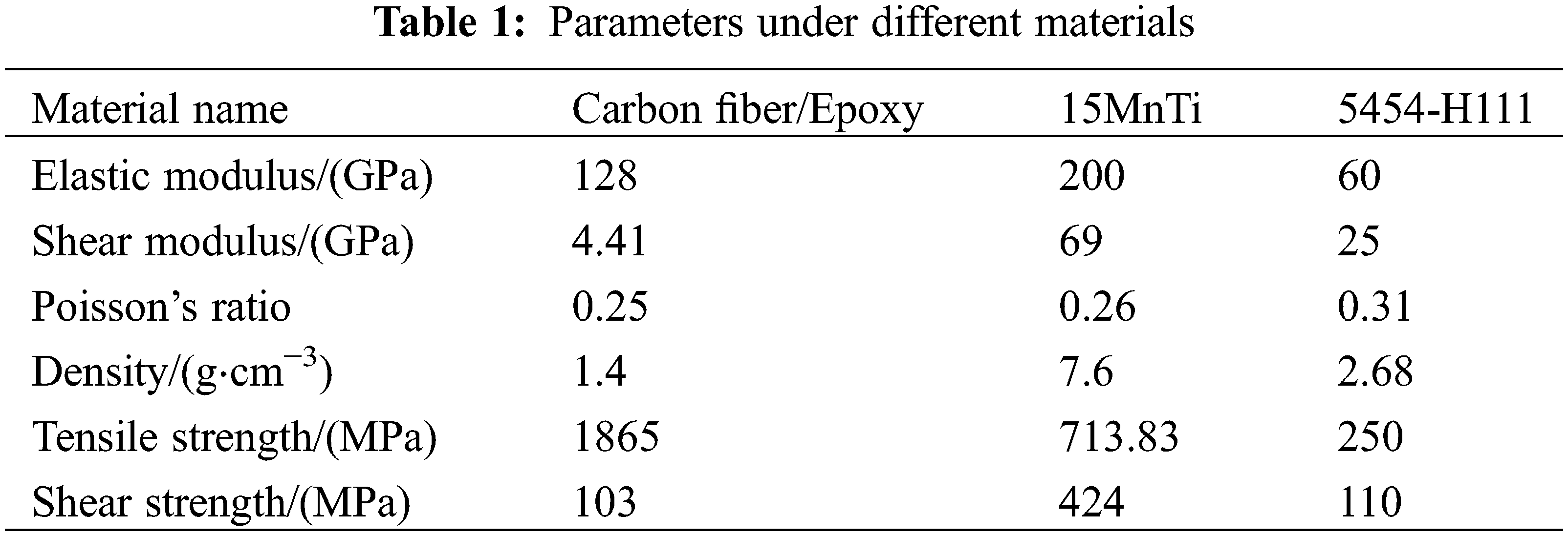
The experimental setting parameters of the model in this paper are shown in Table 1.
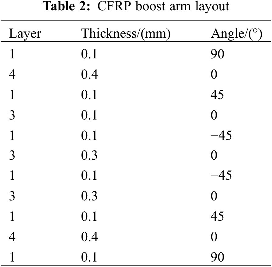
The composite layoff design generally admires a symmetrical laying, requiring the same angle adjacent to 4 layers, continuous reduction is not more than 3 layers, and the specific layoff design is in Table 2.
The fastening design of the composite should be paid to the following two points:
1. The design parameters are unreasonable, which seriously affects the quality of the mechanical connection. National general coal bolts generally include M36, M40, etc. Under normal circumstances, the preload of the bolt should meet the yield strength of the composite material. In line with international standards. However, many domestic coal companies have not yet noticed the important role of preloading. Therefore, in the actual mechanical installation process, due to the unreasonable parameter design, the pre-tightening force is often too low, causing the nut to loosen.
2. In the mechanical device, engineers generally consider more mechanical strength and rigidity at the beginning of design, often ignore elastic design. This has led to a lot of mechanical devices in the actual use of processed places, consisting of corresponding transmission, handling and storage of relevant personnel facilities, and collecting and utilizing information is to establish a comprehensive throughput by using computer technology equipment.
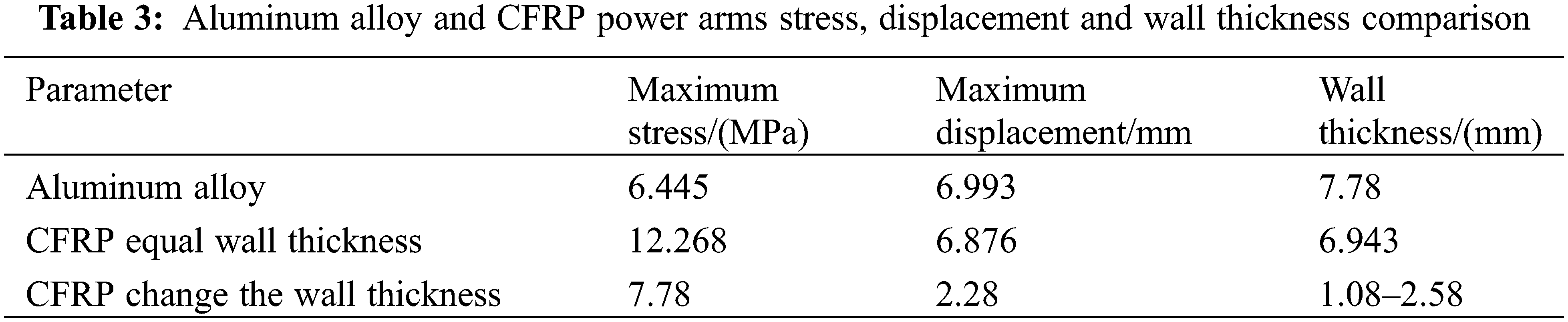
After finite element calculation analysis, the overall stress cloud of wall thickness arm and other wall thickness arms. The overall stress level of CFRP booster arm is low, and the maximum stress is 12.27 MPa, which is much lower than the material strength. At this time, the maximum displacement of the CFRP boost arm is 6.878 mm, which satisfies the structural stiffness requirements of less than 7 mm deformation.
The aluminum alloy and the CFRP robot arm are stressed, displacement, and wall thickness, such as Table 3. It can be seen from Table 3 that the wall thickness of the aluminum alloy arm is thick and reaches 7.8 mm under the premise of satisfying product performance requirements. At this time, the wall thickness of the CFRP robot can be controlled within 3 mm. Under the requirements of the amount of 7 mm deformation, the weight of the thickness CFRP and the aluminum alloy mechanism of the same structure can be reduced by 89.4%.
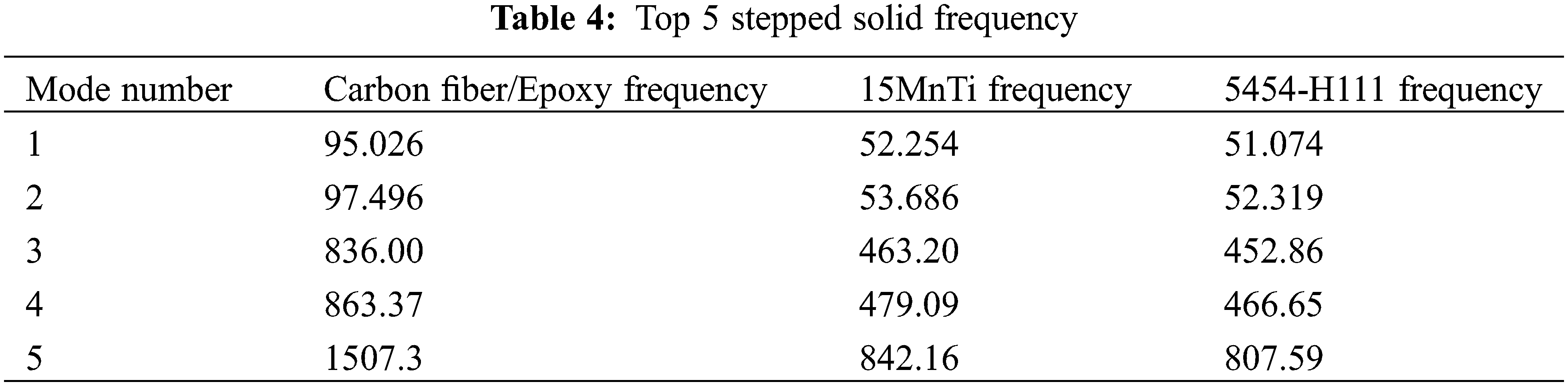
The harmonicity is related to the inherent frequency of the system, and the system of solid-saving frequency is calculated in the determined structural material, constraint, and reasonable mesh division mode. The first 5-order solid frequency of the helper arm in different materials is calculated by Solid-Works Simulation, as shown in Table 4.
Hinge constraints are applied by applying hinge constraints on the left end of the auxiliary arm, and the right end is the free end. The pile harmonic moment is loaded on the reducer connection to achieve rotational movement in the horizontal plane, as shown in Table 5.
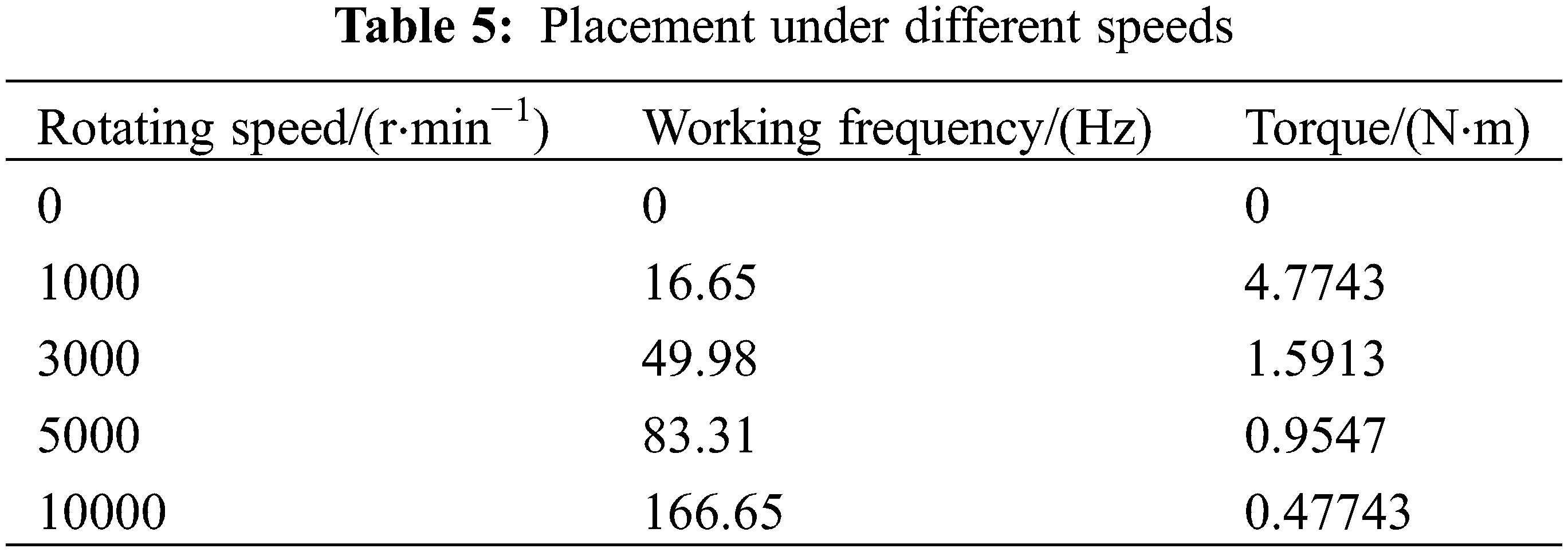
The maximum displacement, speed and acceleration of the three materials appear at 2 step solid frequency; the displacement of the carbon composite power arm has a significant peak at 16 Hz, slightly less than the maximum displacement value, which may be due to operating frequency. The torque is mutated on 16. 67 Hz, causing the helper arm to produce peaks there. The main feature parameters under different materials are shown in Table 6.
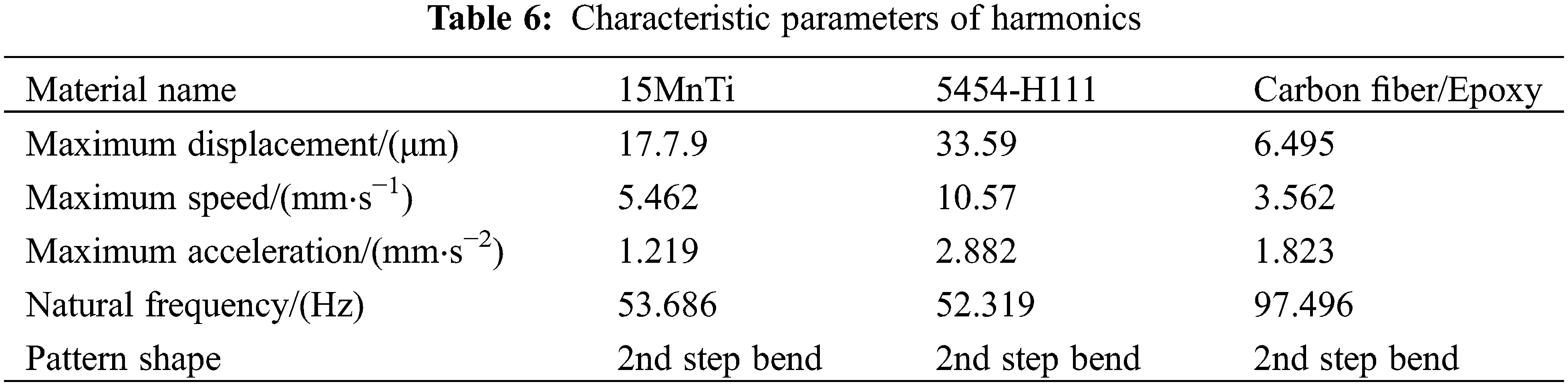
As can be seen from Table 6, the maximum vibration response of the power arm under different materials occurs at the inherent frequency of the structure and the working frequency coincidence, wherein the helper arm of the carbon fiber/epoxy composite is minimum. Within the entire operating frequency range, the speed and acceleration of the aluminum alloy is the largest.
By applying a fixed constraint by applying a fixed constraint on the left end of the helper arm, load the axial impact load of 20 g of the acceleration size at the right end connector slot, and the point of selecting the maximum displacement is based on aluminum.
Further, the displacement of the carbon fiber/epoxy composite boost arm is smoother than the aluminum alloy, indicating that the former is more conducive to maintaining the stability of the booster arm during exercise. The main feature parameters of axial loading transient vibration are shown in Table 7.
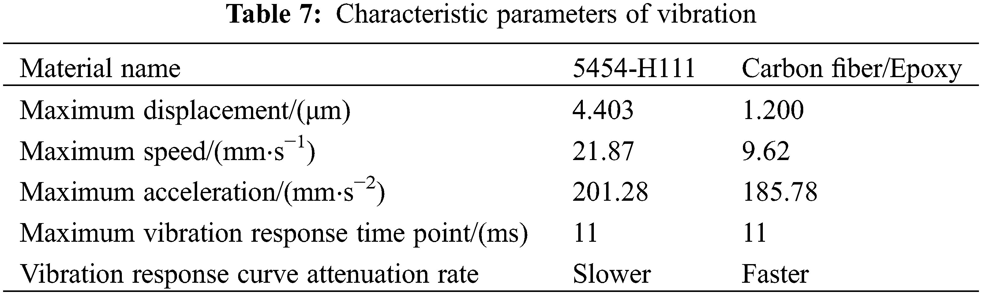
It can be seen from Table 7 that the vibration of the Carbon fiber/epoxy composite power arm is smaller after being affected by the axial impact load, and the vibration attenuation is more pronounced.
The maximum displacement of the aluminum alloy and Carbon fiber/epoxy composite boost arm appears at 11 ms, where the maximum displacement value of the aluminum alloy arm is about 4.3 times the maximum displacement value of the Carbon fiber/epoxy composite power arm. And the latter’s vibration attenuation is much greater than the former, and the effect of vibration attenuation is also significantly better than the former. The vibration of the power arm can be attenuated in a short time. Stadium. The main feature parameters of radially loading transient vibration are shown in Table 8.
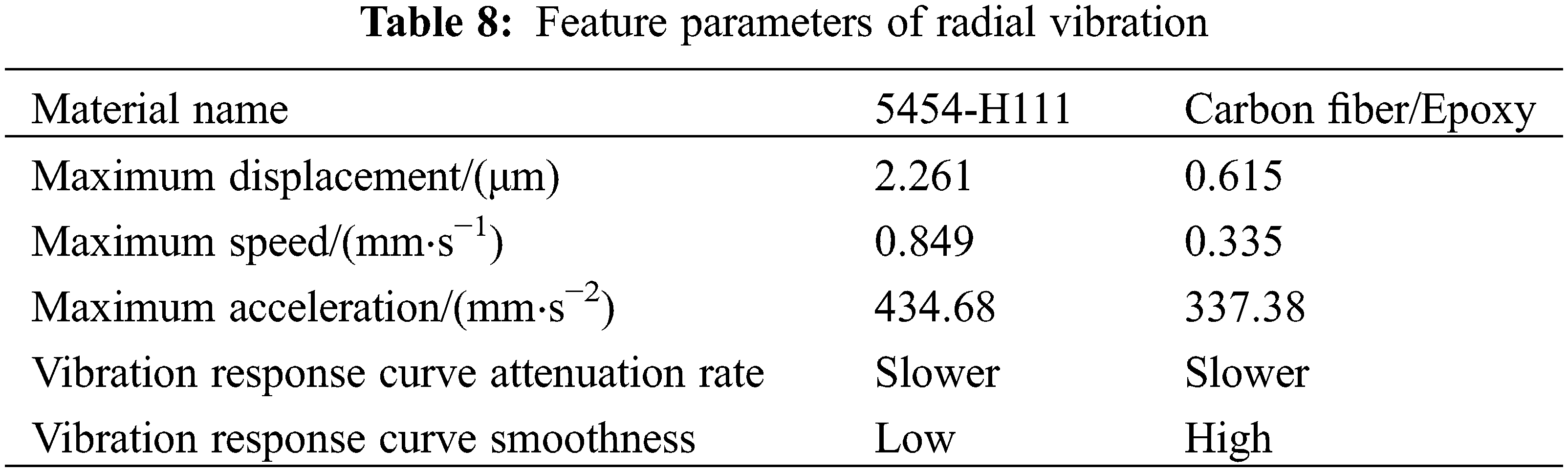
It can be seen from Table 8 that the vibration of the Carbon fiber/epoxy composite power arm is equally small under radially impact load, and the vibration decrease rate is faster, and therefore, during the power of the power arm, the carbon fiber/epoxy composite material is The vibration of the power arm has a better inhibitory effect.
Based on three structural materials: alloy steel, aluminum alloy and carbon fiber/epoxy composite material, a three-dimensional model of the support arm was designed, and harmonic analysis and transient vibration analysis were performed using SolidWorks simulation software. From the harmonic analysis, it can be seen that the vibration response power of the battery of different materials occurs when the natural frequency of the structure coincides with the working frequency, the speed and acceleration vibration response peaks are in alloy steel, aluminum alloy, and the torque acts on the torque on the booster arm. The research results in this paper provide a basis for the design of the flexible booster arm and its vibration reduction problem, and have certain practical application value.
Funding Statement: Thank the editor for his careful review, the reviewer for his careful review and all the staff of the team. This work was financially supported by Scientific Research Fund of Yunnan Institute of Engineering (2019gchy01).
Conflicts of Interest: The authors declare that they have no conflicts of interest to report regarding the present study.
1. Sun, K., Hu, X. Y., Li, D., Zhang, G. D., Zhao, K. et al. (2021). Analysis of bubble behavior in a horizontal rectangular channel under subcooled flow boiling conditions. Fluid Dynamics & Materials Processing, 17 (1), 15–21. DOI 10.32604/fdmp.2021.013895. [Google Scholar] [CrossRef]
2. Yu, H., Wang, Y. H. (2020). Application and prospect of carbon fiber reinforced resin group composite material. Synthetic Fiber Industry, 43(1), 55–59. DOI 10.13700/j.bh.1001-5965.2020.0146. [Google Scholar] [CrossRef]
3. Bai, S., Bao, F., Zhao, F. Z. (2021). On the efficiency of a CFD-based full convolution neural network for the post-processing of field data. Fluid Dynamics & Materials Processing, 17(1), 87–98. DOI 10.32604/fdmp.2021.010376. [Google Scholar] [CrossRef]
4. Bao, J. W., Jiang, S. J., Zhang, D. J. (2018). Development status and trend of aviation carbon fiber resin base composites. Technology Heading, 36(19), 52–63. DOI 10.16208/j.issn1000-7024.2018.03.031. [Google Scholar] [CrossRef]
5. Yang, P. J., Yuan, Z. M., He, L. P. (2017). Research progress of carbon fiber surface modification and its influence on carbon fiber/resin. Midament, 31(7), 129–136. DOI 10.13195/j.kzyjc.2017.1290. [Google Scholar] [CrossRef]
6. Xue, Z. (2017). Study on the system of wearable pneumatic muscle assistance arm system. Geophysical Information, Northeast University. [Google Scholar]
7. Song, Y. L., Yang, L., Guo, W. (2016). Key technology for carbon fiber composites in automotive lightweight applications. Modules, 30(17), 16–25. DOI 10.19734/j.issn.1001-3695.2016.09.0579. [Google Scholar] [CrossRef]
8. Zhang, Q. J. (2016). Basic study of functionalized carbon nanotube carbon fiber multi-scale enhanced epoxy resin group. Engineering Technology, Beijing Chemical Technology. [Google Scholar]
9. Yang, Z., Zhang, B. M., Shui, Y. J., Zhang, J. B., Tang, Z. W. et al. (2017). Research progress of space mirror manufacturing technology of carbon fiber composite materials. Journal of Composite Materials, 34(1), 1–11. DOI 10.19678/j.issn.1000-3428.0056980. [Google Scholar] [CrossRef]
10. Li, S. M. (2015). Study on the preparation and performance of structural-energy storage carbon fiber/epoxy resin group. Modern Technology, Jiangsu University. [Google Scholar]
11. Liu, G., Luo, C., Li, X. Q., Zhang, D. J., Yan, S. L. et al. (2012). Simulation and manufacturing verification of RTM forming process of composite materials. Journal of Composite Materials, 29(4), 105–112. DOI 10.13718/j.cnki.xsxb.2012.11.015. [Google Scholar] [CrossRef]
12. Qiao, R. H. (2006). Preparation and mechanical properties of carbon nanotube continuous carbon fiber reinforced epoxy resin group. Geophysical Information, Beijing Chemical Technology. [Google Scholar]
 | This work is licensed under a Creative Commons Attribution 4.0 International License, which permits unrestricted use, distribution, and reproduction in any medium, provided the original work is properly cited. |