| Fluid Dynamics & Materials Processing |
DOI: 10.32604/fdmp.2022.019470
ARTICLE
Experimental Evaluation of the Mechanical Properties of Cement Sheath under High-Temperature Conditions
1Yangtze University, Wuhan, 430199, China
2Downhole Service Company, CNPC Chuanqing Drilling Engineering Co., Ltd., Chengdu, 610052, China
3Chuanxi Drilling Company, CNPC Chuanqing Drilling Engineering Co., Ltd., Chengdu, 610051, China
4China National Logging Corporation Southwest Branch, Chongqing, 401147, China
5China University of Geosciences, Wuhan, 430074, China
*Corresponding Authors: Zhiqiang Huang. Email: huangkwx@163.com; Deng Qiao. Email: dengqiao2008@163.com
Received: 26 September 2021; Accepted: 11 November 2021
Abstract: The sealing integrity of cement sheath in offshore wells is seriously threatened under high-temperature conditions, resulting in gas channeling and other problems. Given the lack of experimental results, in this study relevant samples of a cement slurry sealing section of a typical offshore high-temperature well have been prepared and analyzed. In particular, the mechanical properties have been assessed with a triaxial pressure servo instrument and a high-temperature curing kettle. The density and the Poisson’s ratio of the samples have also been tested. The stress-strain curve has been drawn to obtain the elastic modulus and the compressive strength. The rock brittleness index has been calculated according to the measured elastic modulus and the Poisson’s ratio, together with the brittleness and the compressibility of the cement samples. The test results show that the mechanical properties and bonding strength of the cement samples are optimal at 130°C, medium at 150°C, and poor at 180°C.
Keywords: High-temperature wells; cement sheath; mechanical properties; triaxial test; brittleness index
Over the last few years, the exploration and development of offshore oil and gas has been increasing. However, limited by extreme working conditions and ultra-high temperature, offshore drilling faces a series of huge challenges. Some conventional drilling and completion technologies cannot meet the needs of offshore high-temperature operation conditions, and how to ensure the sealing integrity of cement sheath under high-temperature conditions is a technical problem [1]. As the cementing slurry solidifies, the cement sheath can seal the formation to protect the safe production of oil and gas. The mechanical properties of cement sheath is important, which is directly related to the quality of cementing [2–5]. Due to the high-temperature and complex rock mechanical properties in deep-water wells, the integrity of cement sheath is easy to be damaged, resulting in annular space gas channeling [6–11]. At present, the variation law of mechanical property parameters of cement sheath under different high-temperature conditions is not clear.
The mechanical properties of cement sheath has attracted the attention of researchers. The test on the anti-channeling of cement sheath have been conducted, exploring the damage mechanism of cement sheath during perforation. A device has been designed to test the dynamic performance of multifunctional cement material, which the dynamic mechanical properties of original cement stones and modified cement stones have been studied [12]. The mechanical deformation behavior of cement stone under different temperature conditions have been studied by using the RTR-100 triaxial rock mechanics test system [13]. The mechanical properties of sandstone under normal temperature and ultra-high temperature have been studied by using the electro-hydraulic servo material mechanics test system, which the change characteristics of the full stress-strain curve, peak stress, peak strain, and elastic modulus of sandstone have been investigated [14]. The experimental research on the triaxial compressive strength of cement sheath have been carried out, which the mechanical property parameters have been obtained [15]. The test to evaluate the performance of two cement slurry systems commonly used in the actual horizontal wells have been conducted [16]. The influence of temperature variation of cement sheath in the wellbore has been studied, the model of cement sheath by considering thermal solid coupling has been established [17].
Some studies have been carried out for the mechanical integrity of the cement sheath from cementing to production. A casing-cement sheath-stratum system coupling mechanical model by using the theory of elastoplastic mechanics have been established, solving the Tresca stress and radial displacement of the cement sheath. Combined with the rock mechanics parameters obtained from the tailpipe cement stone triaxial stress experiment in a field well, the mechanical integrity evaluation of the cement sheath in the tailpipe cementing section have been carried out [18]. A mechanical model of the cement sheath by considering the initial stress state of the cement sheath have been built. The results show that the radial prestressed cementing technology can effectively prevent gas channeling [19]. The mechanical performance test of the deep brittle shale under different unloading confining pressure speed have been carried out. The mechanical properties and failure laws of deep brittle shale under complex working conditions have been studied [20].
The above research has discussed the related problems of mechanical properties of cement stones in detail, but the objects in the studies are mainly the cement sheath under normal temperature and pressure conditions. There are few researches on the experimental testing of the mechanical properties of cement sheath under high temperature conditions [21–23]. In this paper, the mechanical properties of cement sheath under high-temperature conditions have been tested by using tuses triaxial pressure servo instrument and high-temperature curing kettle devices, the triaxial compressive strength, elastic modulus and Poisson’s ratio of the cement sheath have been obtained. On this basis, the cohesion and internal friction angle of cement sheath have been calculated according to Moore Coulomb’s law. This study can provide theoretical basis and important reference for high-temperature cementing.
The mechanical properties of cement stones can be obtained by triaxial tests. In order to simulate the actual stress state of cement stones in downhole, the high-temperature rock mass triaxial testing machine has been used to determine the compressive strength, elastic modulus, Poisson’s ratio and cohesion, and the internal friction angle of cement stones with confining pressure under high-temperature conditions can be calculated. In the triaxial test, the specimen is compressed in three directions, the specimen is under lateral confining pressure, and the pressure is applied in the axial direction. The cement sample is installed with matching the hydraulic oil and vacuum. By increasing the confining pressure (σ2 = σ3) to the specified value, keeping the confining pressure unchanged, resetting all kinds of displacement sensors, the experimental procedure is launched until the sample is broken. The compressive strength, elastic modulus and Poisson’s ratio of cementing stone are calculated as follows:
where
where
The Poisson’s ratio of cement stone is the ratio of radial strain (transverse strain) to axial strain (longitudinal strain) of cement stone under unidirectional compression, which is the ratio of transverse elongation to longitudinal shortening:
where
When calculating the elastic modulus and Poisson’s ratio of cement stone, the elastic state segment of its stress-strain curve should be used, otherwise it will cause a larger error. According to the elastic modulus and Poisson’s ratio, the brittleness index of cement stone can be calculated, and the brittleness index of cement stone elastic parameter method is used to calculate the brittleness index:
where
The brittleness evaluation standard of cement stone refers to the brittleness evaluation standard of rock, and the brittleness index is greater than 50%. It can be considered that the brittleness of cement stone is larger and the compressibility is better. If it is between 40% and 50%, it can be considered that the brittleness of cement stone is general, and the compressibility is moderate. If it is less than 40%, it can be considered that the cement stone has low brittleness and poor compressibility [12].
In this experiment, the proportion and dosage of reagent configured with cement slurry are more difficult under high-temperature conditions to quantify than that in normal temperature. The quality of cement slurry produced is difficult to control by using high-temperature curing kettle to cure and prepare cement slurry. The principle of sample preparation used in the experiment is based on the standards of International Association of Rock Mechanics.
The sample height is about 50 mm, the diameter is about 25 mm, and the base surface deviation is within 2.5%. The cement composition formula is as follows: water + G-grade cement + 50% heat stabilizer + 5% self-repairing material + 2% anti-channeling enhancer + 1% latex defoamer + 3.5% fluid loss agent + 8% latex + 1% dispersant + 1.5% high temperature retarder + 0.5% medium temperature retarder. Cement stones are cured at 130°C, 150°C, and 180°C to prepare three groups, which are cored, as shown in Fig. 1. The specific production process of the cement stones is as follows:
(1) The cement slurry system is mixed in proportion, and the high-speed mixer is used to mix to prepare the cement slurry.
(2) The configured cement slurry is poured into a cylindrical mold with diameter of 25.4 mm and height of 50 mm.
(3) The cement stone test model is put into the high-temperature curing kettle, and the cement stone is took out after curing for 7 days under high-temperature conditions.
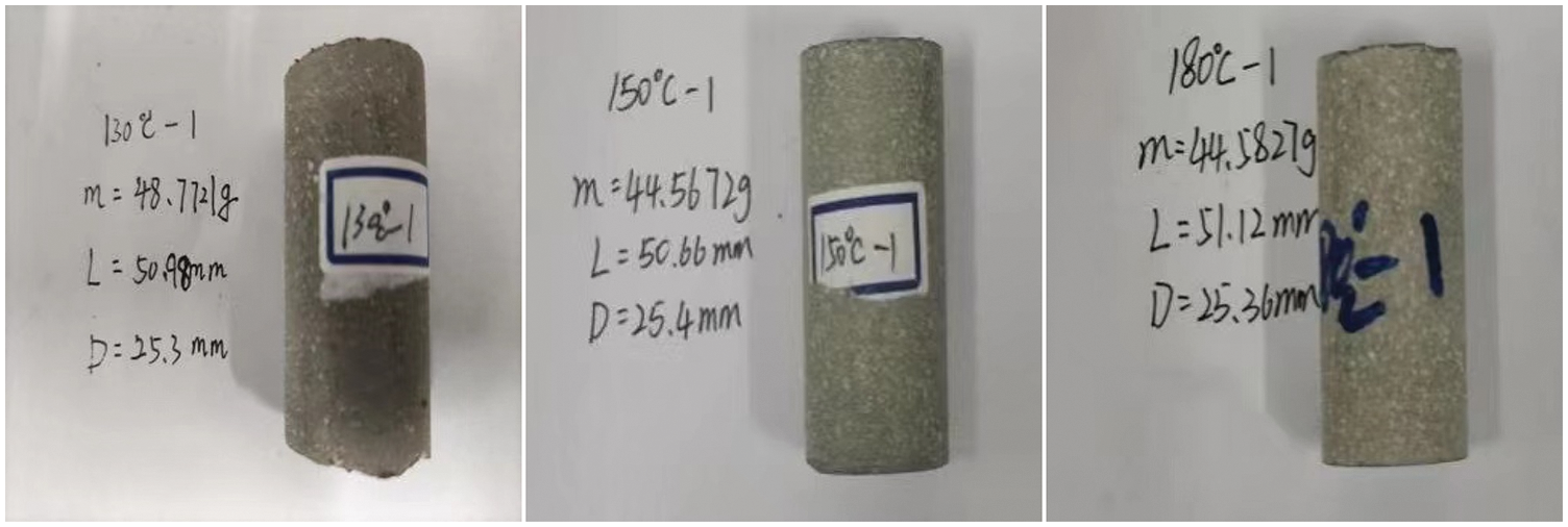
Figure 1: Cement stones curing at 130°C, 150°C, and 180°C
As the cores taken from the site are generally irregular in shape, which cannot be directly used for experiments. It is necessary to machine the on-site core before the experiment. The machining process of indoor core is as follows: Firstly, the cylindrical sample is taken out from the field core by diamond coring bit; then, both ends of the cylindrical sample are polished flat, the deviation of the base surface is within 2.5%, and the aspect ratio of the sample is 1.5, as shown in Fig. 2.
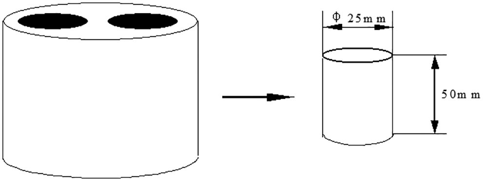
Figure 2: Sampling diagram
The high-temperature rock mass triaxial testing machine is shown in Fig. 3, and the auxiliary equipment is a high-speed mixer and a high-temperature curing kettle. The high-temperature rock mass triaxial testing machine is composed of five main parts: a high-pressure triaxial chamber, a confining pressurized system, an axial pressurized system, a heating and constant temperature system, and a data acquisition control system. The design index of the triaxial chamber is 200 MPa, the temperature is 200°C, and the diameter of the sample that can be accommodated is 25 mm and 50 mm. The compressive strength of cement stone tested by the equipment is the limit value when the sample reaches failure under uniaxial pressure, which is equal to the maximum compressive stress at failure in value. The compressive strength of cement core is generally measured, and the schematic diagram of the compressive strength test is shown in Fig. 4.
During the test, the core is processed into cement samples. The processed cement samples are placed on the testing machine. The pressure rate is controlled, and the corresponding load of the cement samples is recorded in real time. As the load applied to the end face of the cement sample through the indenter reaches the ultimate strength that the cement sample can withstand, the cement sample is damaged. The compressive strength of cement samples can be obtained by Eq. (1) with the corresponding load divided by the action area. The pressure plate in Fig. 4 can be regarded as the indenter of the test press, and β is the rupture angle.
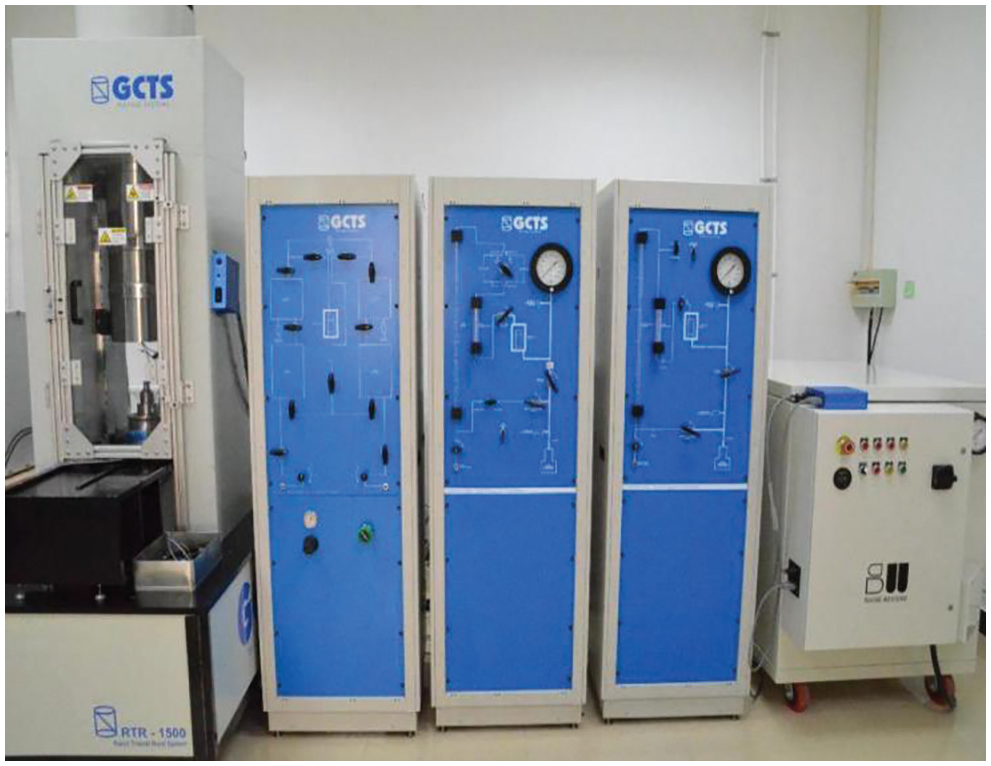
Figure 3: High-temperature rock mass triaxial testing machine
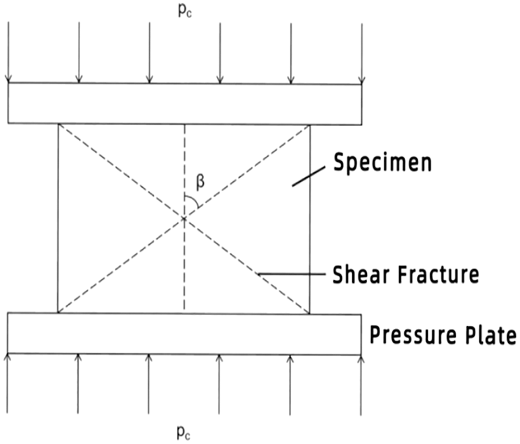
Figure 4: Schematic diagram of compressive strength test
The test is carried out under the condition that the confining pressure is lower than the axial pressure, and the mechanical property parameters can be obtained by the test system. The cement sample can be placed in the center of the bearing plate of the testing machine after measuring the size of the prepared cement sample. The axial displacement sensor, lateral displacement sensor and acoustic emission sensor are respectively adjusted.
At the beginning of the triaxial test, the cement sample is loaded stepwise. The confining pressure is applied to a certain value through the high-pressure pump, and then the hydraulic press is turned on to apply the axial load to the cement sample, which the specimen can offset the upward force of the plunger caused by the confining pressure. As the confining pressure is increased to the expected level, the confining pressure is stabilized and the axial load is continued to expand until the cement sample is damaged. After stopping the loading, the load applied to the axial direction of the sample can be obtained, which is the difference between the axial load when the sample is broken and that as the confining pressure is stable. The data can be collected automatically or manually during the test, and the full stress-strain relationship curve can be drawn.
Based on the above experimental steps, the indoor test of cement samples is completed. The triaxial mechanical property parameters of the cement samples under effective stress can be obtained, and the representative test curves can be drawn. The tables of the cement sample test results are listed and the experimental data are analyzed.
According to the reference standard for the evaluation of the bond strength between the cement sheath and the formation rock [7], when the compressive strength of the formation rock is less than or equal to 20 MPa, the bond strength of the second interface with the cement sheath is poor. When the compressive strength of the formation rock is 20–30 MPa, the bond strength of the second interface of the cement sheath is medium. When the compressive strength of the formation rock is 30–40 MPa, the bond strength of the second interface with the cement sheath is good. When the compressive strength of the formation rock is greater than or equal to 40 MPa, the bond strength of the second interface with the cement sheath is excellent. According to this evaluation standard, the bonding strength quality of the second interface between the formation rock and the cement sheath can be evaluated based on the results of the core rock mechanics parameters obtained by the triaxial test. The results of the evaluation of the second interface between the formation rock and the cement sheath are shown in Tables 1–3.
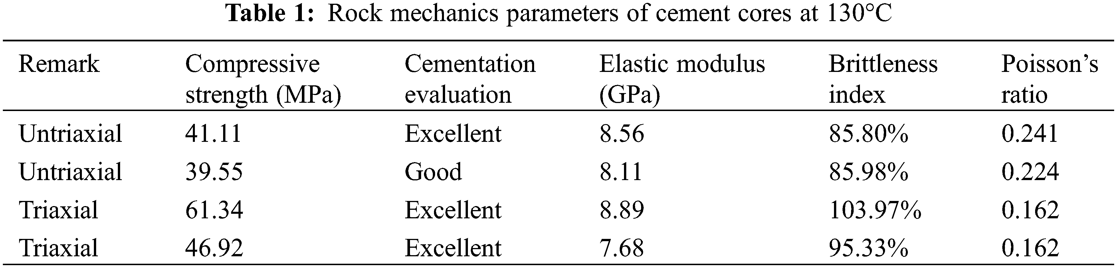
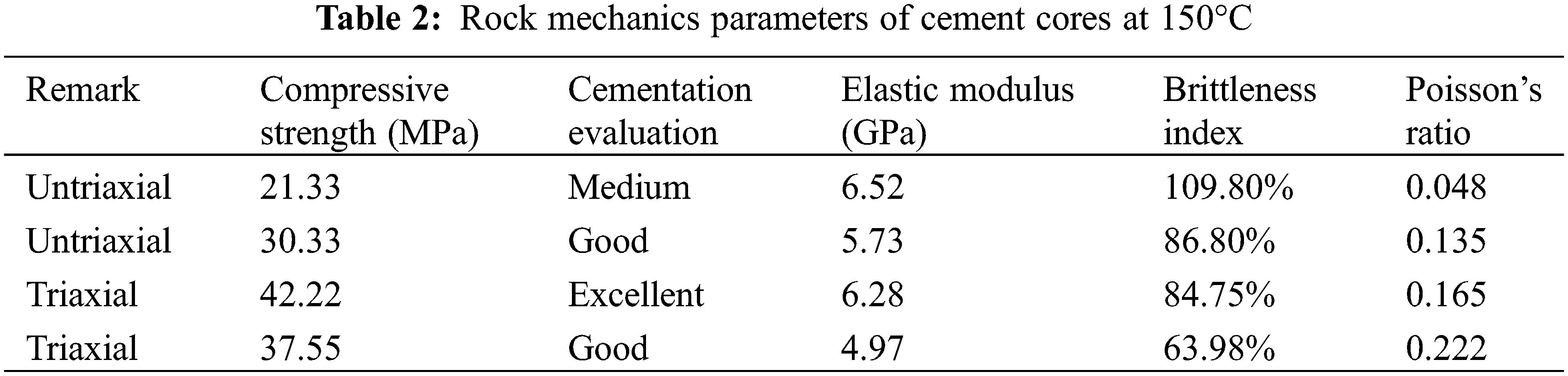
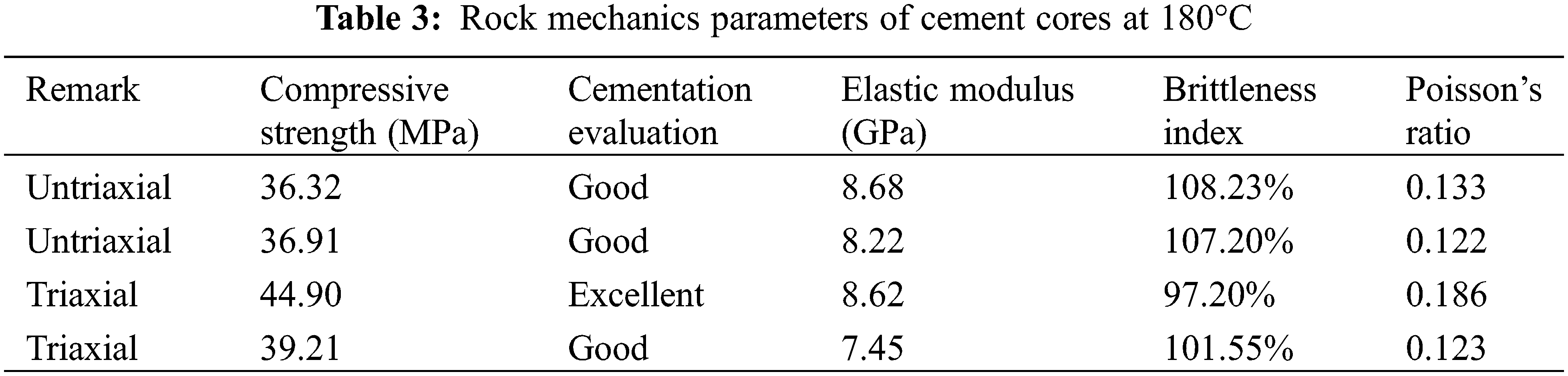
Comparing these experimental temperatures, it can be seen that the bonding strength of the second interface between the formation rock and the cement sheath is the lowest at 150°C, medium at 180°C, and the best at 130°C. The compressive strength of the cement stone sample at 150°C is 42.22 MPa, the compressive strength of that in other layers is respectively 21.33 MPa, 30.33 MPa, and 37.53 MPa, and the modulus of elasticity is 4.9–6.5 MPa, which is much smaller than that at 130°C and 180°C. Therefore, the mechanical properties of cement stone at 150°C are the worst, the first interface and the second interface of the cement sheath are most easily damaged because the second interface has the worst bond strength with the formation. However, the cement stone under the condition of 180°C has a medium cementation strength as a whole, and there is no large variation drop. On the whole, the bonding strength of the second interface at 180°C is better than that at 150°C, but it is inferior to the bonding strength of the second interface at 130°C. It can be shown that in each group of experiments under the same temperature, the cementation effect of cement core samples tested under triaxial test conditions is better than that under uniaxial test conditions. The reason can be inferred from Mohr circle: the triaxial compressive strength of core is greater than that of uniaxial compressive strength.
The minimum compressive strength of the cement stone sample is 21.33 MPa, which occurs at 150°C. The maximum compressive strength is 61.34 MPa, which occurs at 130°C. When the compressive strength of the cement core is the largest, the elastic modulus is also the largest, and the brittleness index is also relatively large, which can be regard as a hard cement stone. From Table 2, it can be seen that the softest cement stone appears at 150°C, which the compressive strength is 21.33 MPa. The Poisson’s ratio is the minimum value of 0.048, the elastic modulus is relatively small and the bonding strength of the second interface of the soft cement sheath is unfavorable. As the elastic modulus and compressive strength of the formation are small, the cement sheath is easier to break. As the bonding strength of the corresponding second interface is weaker, the corresponding first interface is more likely to be damaged by tensile resistance, which can affect the strength of the casing. Therefore, in the formation section with weak rock mechanical strength, the strength and steel grade of the casing should be increased to prevent various damages of the casing.
Several groups of high-temperature triaxial tests on the cement cores have been carried out, and three sets of typical stress-strain curves of cement cores have been selected for analysis and evaluation. The stress-strain curves of cement cores by triaxial tests at 130°C, 150°C and 180°C can be obtained respectively, as shown in Figs. 5–7. It can be seen that the stress-strain curves of cement cores at 130°C and that at 180°C are relatively smooth. The above curves have similarities that the stress and axial strain basically have a linear relationship at the beginning, as shown in the right half of the stress-strain curves under 130°C and 180°C. The elastic modulus of cement cores obtained in the experiment is the slope of the stress-axial strain curve. In the section approaching the top of the curve, the elastic modulus gradually decreases as the stress gradually increases. The reason is that the cement core gradually reaches its failure limit.
When the stress increases to the apex, the cement core begins to rupture. The reason is that the stress value at the apex is the triaxial compressive strength value of cement core. After reaching the apex, the curve goes down as the section represents the failure stage of the cement core. Due to the fracture of the cement core, the stress drops sharply or gradually while the axial strain increases sharply or gradually.
As shown in Fig. 6, it can be found that the curve characteristics are quite different from those in Figs. 5 and 7. The stress-axial strain curve in Fig. 6 reached the first peak faster, and the stress value decreased after a certain value. Then the stress value begins to rise, reaching the second peak. This phenomenon appeared in the curve four times, and then the curve gradually became flat. It indicates that the cement core reaches the rupture stage faster at 150°C than 130°C or 180°C, but there is no obvious regularity between the core rupture speed and the final rupture.
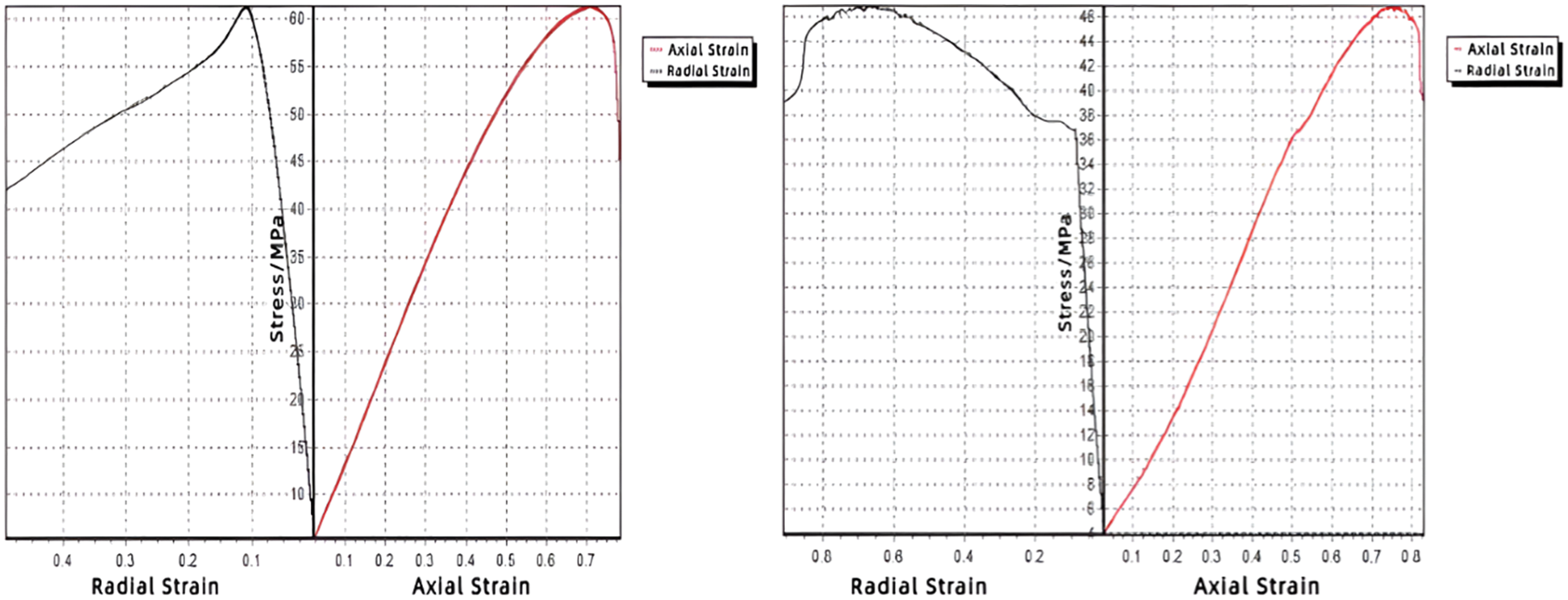
Figure 5: Stress-strain curve of cement core at 130°C
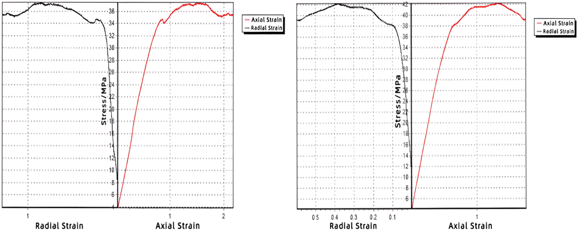
Figure 6: Stress-strain curve of cement core at 150°C
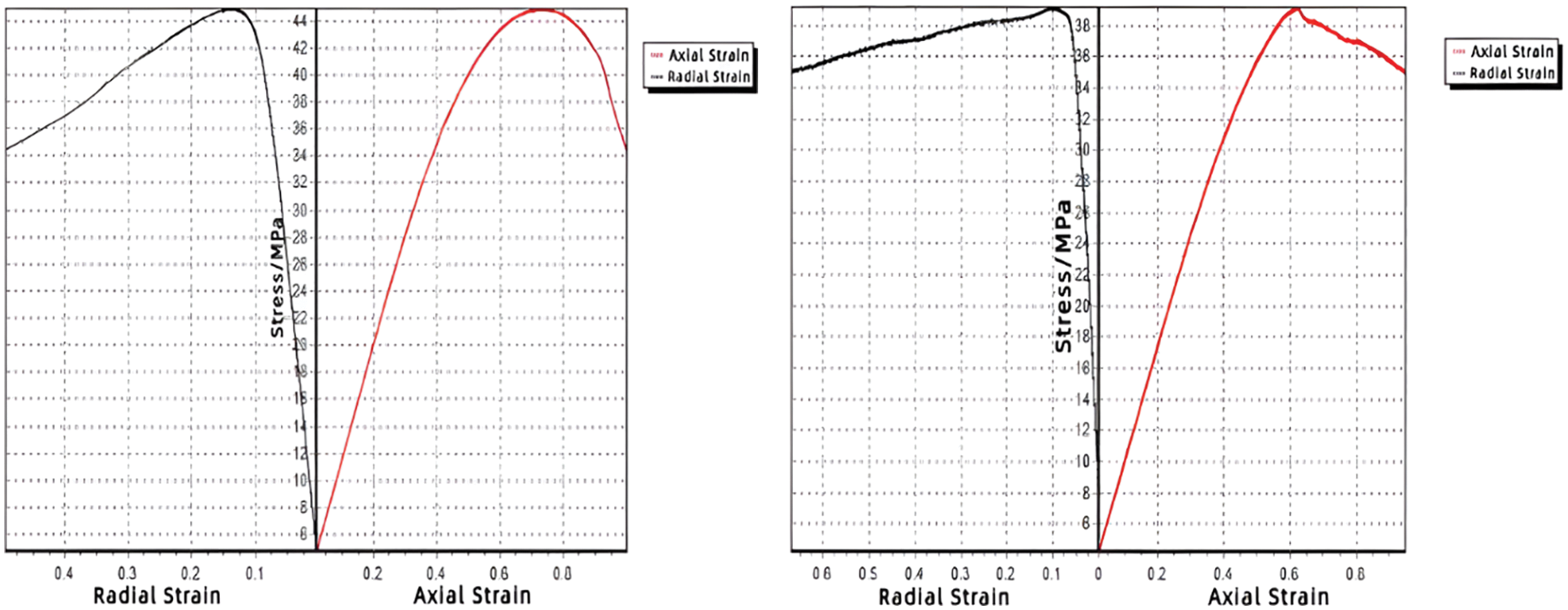
Figure 7: Stress-strain curve of cement core at 180°C
Based on the real parameters of cement stones in the experiment, the 3D physical model can be established with the height of 50 mm and the diameter of 25 mm, as shown in Fig. 8. The mesh model is divided into hexahedral meshes, as shown in Fig. 9. The mean grid spacing is 3 mm and the total number of grids is about 5000. Based on the above models, the numerical simulation has been carried out on the software in the computer. The simulated results show that the mechanical properties of the cement sheath at 130°C are better than 150°C and 180°C, which is mutually verified with the experimental results.
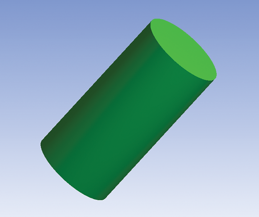
Figure 8: 3D physical model of cement stones
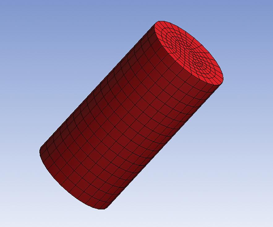
Figure 9: Mesh model of cement stones
For high-temperature cementing operation conditions, the elastic modulus, compressive strength, Poisson’s ratio and other mechanical property parameters of cement sheath have been obtained by triaxial tests, and the stress-strain curves of cement sheath have been drawn. The following conclusions can be obtained:
(1) The mechanical properties of the cement sheath at 130°C are the best while that at 150°C are the worst. The first interface and the second interface of the cement sheath are most easily damaged at 150°C, the reason is that the second interface has the worst bond strength with the formation. The bonding strength of the second interface of the cement sheath at 180°C is better than that at 150°C, which is worse than that at 130°C. This shows that the higher the compressive strength of cement stone, the better the mechanical properties, and the more advantageous to improve the cementation strength of cement sheath.
(2) The stress-strain curve of the cement sheath at 150°C are quite different from 130°C and 180°C. The curve reaches the compressive strength and cracks faster, more attention should be paid to the real-time monitoring of the cement sheath at 150°C during on-site cementing construction.
(3) The smaller the elastic modulus or compressive strength of the formation, the easier the cement sheath is to crack. The weaker the bonding strength of the corresponding second interface, the easier the corresponding first interface is to be damaged by tension, affecting the strength of the casing. Therefore, in the formation section with weak rock mechanical strength, the strength and steel grade of the casing should be increased to prevent various damages of the casing. In the formation section under the construction condition of 150°C, the steel grade and wall thickness of the casing should be increased to prevent the integrity of the cement sheath from failing and causing annulus pressure.
Acknowledgement: The authors gratefully acknowledge the research project from Engineering Research Center of Rock-Soil Drilling & Excavation and Protection, Ministry of Education; China University of Geosciences, Wuhan (Grant No. 202106).
Funding Statement: The authors received no specific funding for this study.
Conflicts of Interest: The authors declare that they have no conflicts of interest to report regarding the present study.
1. Li, Z., Xie, R. J., Wu, Y., Yuan, J. L. (2021). Progress and prospect of CNOOC’s oil and gas well drilling and completion technologies. Natural Gas Industry, 41(8), 78–185. DOI 10.3787/j.issn.1000-0976.2021.08.016. [Google Scholar] [CrossRef]
2. Carter, L., Evans, G. (1964). A study of cement-pipe bonding. Journal of Petroleum Technology, 16(2), 157–160. DOI 10.2118/764-PA. [Google Scholar] [CrossRef]
3. Morgan, D. R. (1989). Field measurement of strain and temperature while running and cementing casing. SPE, 321–330. DOI 10.2118/SPE-19552-MS. [Google Scholar]
4. Ladva, H. K., Craster, B., Jones, T. G., Goldsmith, G., Scott, D. (2004). The cement-to-formation interface in zonal isolation. SPE Drilling and Completion, 20(3), 186–197. DOI 10.2118/88016-PA. [Google Scholar] [CrossRef]
5. Boukhelifa, L., Moroni, N., James, S. G., Roy-Delage, S. L., Lemaire, G. (2005). Evaluation of cement systems for oil and gas well zonal isolation in a full-scale annular geometry. SPE Drilling & Completion, 20(1), 44–53. DOI 10.2118/87195-PA. [Google Scholar] [CrossRef]
6. Gray, K. E., Podnos, E., Becker, E. (2007). Finite element studies of near-wellbore region during cementing operations: Part I. SPE Drilling & Completion, 24(1), 127–136. DOI 10.2118/106998-PA. [Google Scholar] [CrossRef]
7. Shadravan, A., Schubert, J., Amani, M., Teodoriu, C. (2015). Using fatigue failure envelope for cement sheath integrity evaluation. SPE 168321, 30(1), 68–75. DOI 10.2118/168321-PA. [Google Scholar] [CrossRef]
8. Andrade, J. D., Sangesland, S., Skropa, R., Todorovic, J., Vrålstad, T. (2016). Experimental laboratory setup for visualization and quantification of cement-sheath integrity. SPE, 31(4), 317–326. DOI 10.2118/173871-PA. [Google Scholar] [CrossRef]
9. Andrade, J. D., Sangesland, S. (2016). Cement sheath failure mechanisms: Numerical estimates to design for long-term well integrity. Journal of Petroleum Science and Engineering, 147(1), 682–698. DOI 10.1016/j.petrol.2016.08.032. [Google Scholar] [CrossRef]
10. Arjomand, E., Bennett, T., Nguyen, G. D. (2018). Evaluation of cement sheath integrity subject to enhanced pressure. Journal of Petroleum Science and Engineering, 170, 1–13. DOI 10.1016/j.petrol.2018.06.013. [Google Scholar] [CrossRef]
11. Long, Y., Wang, J. (2021). A study on the strength surplus coefficient of cement. Fluid Dynamics & Materials Processing, 17(1), 181–187. DOI 10.32604/fdmp.2021.011185. [Google Scholar] [CrossRef]
12. Wang, X. L., Huang, Y. C., Niu, L. J. (1999). A research on preventing and resisting the oil permeation in well cementation. Acta Petrolei Sinica, 20(4), 88–92. DOI 10.7623/syxb199904017. [Google Scholar] [CrossRef]
13. Li, Z. Y., Guo, X. Y., Han, L., Luo, P. Y. (2007). Deformation behavior of oil-well cement stone under confining pressure. Natural Gas Industry, 27(9), 62–64. DOI 10.1016/S1872-5813(07)60034-6. [Google Scholar] [CrossRef]
14. Zhang, L. Y., Mao, X. B., Lu, A. H. (2010). Experimental study on the mechanical properties of rocks at high temperature. Science in China: Technological Science, 40(2), 157–162. [Google Scholar]
15. Lian, Z. H., Sha, L., Chen, S. C., Lin, T. J., Li, M. et al. (2011). Experiment of rock mechanics performance and evaluation of cement bond strength. Drilling and Production Technology, 34(1), 101–103. DOI 10.3969/j.issn.1006-768X.2011.01.035. [Google Scholar] [CrossRef]
16. Wang, Y., Chen, D. J., Yu, Z. Y., Qi, Z. G. (2012). Experimental assessment of the mechanical properties of the cement stone for horizontal wells. Natural Gas Industry, 32(10), 63–66. DOI 10.3787/j.issn.1000-0976.2012.10.015. [Google Scholar] [CrossRef]
17. Gholami, R., Aadnoy, B., Fakhari, N. (2016). A thermo-poroelastic analytical approach to evaluate cement sheath integrity in deep vertical wells. Journal of Petroleum Science and Engineering, 147(2), 536–546. DOI 10.1016/j.petrol.2016.09.024. [Google Scholar] [CrossRef]
18. Lu, Y. F., Zheng, Y. Z., She, C. Y., Tang, G., Liu, X. K. et al. (2013). Analysis of cement-sheath mechanical integrity based on the experiment data of cement paste. Natural Gas Industry, 33(5), 77–81. DOI 10.3787/j.issn.1000-0976.2013.05.014. [Google Scholar] [CrossRef]
19. Liu, Y., Yan, H. B., Yu, X., Feng, Y. Q., Fan, W. H. (2014). Negative impacts of borehole pressure change on cement sheath sealing integrity and countermeasures. Natural Gas Industry, 34(4), 95–98. DOI 10.3787/j.issn.1000-0976.2014.04.015. [Google Scholar] [CrossRef]
20. Fan, Y., Wang, J. J., Liu, H. B., Wu, P. C., Gao, D. W. et al. (2020). Test and analysis of mechanical properties and failure patterns for the deep brittle shale under complex load. Special Oil and Gas Reservoir, 27(4), 143–148. DOI 10.3969/j.issn.1006–6535.2020.04.022. [Google Scholar] [CrossRef]
21. Qiu, Q., Cui, L. (2019). Optimal mission abort policy for systems subject to random shocks based on virtual age process. Reliability Engineering & System Safety, 189(4), 11–20. DOI 10.1016/j.ress.2019.04.010. [Google Scholar] [CrossRef]
22. Akinwamide, S. O., Lemika, S. M., Obadele, B. A., Akinribide, O. J., Abe, B. T. et al. (2019). A study on microstructural and mechanical properties of a stir cast Al (SiC-Mg-TiFe) composite. Fluid Dynamics & Materials Processing, 15(1), 15–26. DOI 10.32604/fdmp.2019.04761. [Google Scholar] [CrossRef]
23. Qiu, Q., Cui, L., Wu, B. (2020). Dynamic mission abort policy for systems operating in a controllable environment with self-healing mechanism. Reliability Engineering & System Safety, 203(4), 107069. DOI 10.1016/j.ress.2020.107069. [Google Scholar] [CrossRef]
 | This work is licensed under a Creative Commons Attribution 4.0 International License, which permits unrestricted use, distribution, and reproduction in any medium, provided the original work is properly cited. |