| Fluid Dynamics & Materials Processing |
DOI: 10.32604/fdmp.2022.018752
ARTICLE
On the Selection of a Composite Material for Two-Wheeler Foot Bracket Failure Prevention through Simulation and Mathematical Modeling
1Department of Mechanical Engineering, Alagappa Chettiar Government College of Engineering and Technology, Karaikudi, Tamilnadu, 630003, India
2Department of Mechanical Engineering, Saveetha School of Engineering, SIMATS, Thandalam, Chennai, Tamilnadu, 602105, India
3Department of Mechanical Engineering, PSG College of Technology, Coimbatore, Tamilnadu, 641004, India
4Department of Mechanical Engineering, K. Ramakrishnan College of Engineering, Tiruchirappalli, Tamilnadu, 621112, India
*Corresponding Author: A. Bovas Herbert Bejaxhin. Email: herbert.mech2007@gmail.com
Received: 15 August 2021; Accepted: 01 November 2021
Abstract: A foot bracket is a metal panel bracket used to mount and support the footrest in two-wheeler systems. It holds the footrest in place while rigidly supporting it. In working conditions, this element has often been observed to fail when specific load-fluctuation conditions are established at its rear end. Appropriate materials therefore need to be identified to overcome such a recurring failure. To address these issues, the present study has been implemented with the specific objective to determine the response of selected Al6061-T6 and Al7075-T6 Hybrid Metal Matrix Composites (HMMC). The results, obtained using the ANSYS Software, show that the selected composites can withstand 636,962 N/m² of maximum stress and 8.88 × 10⁻⁶ m of minimum displacement. These results are also compared with relevant mathematical models and it is concluded that the identified material combination provides the required improvement of structural stability that can withstand the load fluctuation on the foot bracket.
Keywords: Foot bracket; Al6061-T6 alloy; CREO; ANSYS; stress; displacement
Growing urbanization and industrialization triggered the population mobility from rural to urban and in the suburban. Lack of adequate public transport, people increasingly preferred to use individualized transport like two-wheeler motorcycles. Presently, the foot bracket in the two-wheeler motorcycle is made up of Al 6061-T6. It is observed that composite material foot bracket was subjected to fracture while the increases in the load at the rear end. It leads to frequent failure of the foot bracket. Considering the importance of this problem, Agostoni et al. [1] tried to alleviate the problem, by modifying the footplate geometry. He also reported that modified footplate geometry minimized the nodal displacement and found that it was effective. Even though it was effective, the researcher did not consider the withstanding stress on the foot bracket. Hence, with this result, one cannot be sure about it may alleviate the above-mentioned problem completely. Atrian et al. [2] have discussed that the elevation of the strength, stiffness, and hardness of the manufacture of foot bracket that leads to it acting as a fracture shield by the combination of these reinforced particles in the metal matrix composite. To address this recurring issue, the present study is carried out with the specific objective of finding the maximum holding stress and minimum displacements of selected Al6061-T6 and Al7075-T6 Hybrid Metal Matrix Composite (HMMC) using ANSYS Software. When SiC particulate is added to aluminium alloys 6061 and 7075, the yield strength improves, as mentioned by Ravi et al. [3–6] 2019 have investigated the mechanical characteristics of alloys Al 6061 and Al 7075; especially, when reinforcing particles are introduced to Al 6061 cross composites, the tensile stress and impact value of Al 6061 are demonstrated to be increased when compared to Al 7075 cross composites. Bejaxhin et al. [7], have been experimentally validated as the influence of different coatings on the electrodes utilized in the EDM process for the improvement of surface roughness. The outstanding surface roughness has been achieved as a result of the particle deposition of Ti, Al, and Cr in PVD coatings, which is more dominant on roughness. Bejaxhin et al. [8], have discussed that the hardening effects of D3 steel material and the influences of tool coatings on surface coarseness with the additional simulative outcomes. Hutchinson [9], and Campbell [10] have addressed that the metal matrix composites with aligned fibres that had good directional stiffness and strength. Based on the anisotropic static material properties of these composites given in the simulation platforms, as well as the stiffness, young’s modulus, and Poisson’s ratio, the composites have been considered anisotropic, meaning that the geometrical properties may change in any direction despite the fact that the geometrical properties are the same.
Aboelseoud et al. [11], have given the present technique and assumptions, investigate the flexural behaviour of an in-service HCB and forecast the maximum compressive strain in the concrete. The induced stresses were measured experimentally and predicted theoretically when the concrete arch was poured and under various load situations. Meenakshi et al. [12], discussed hybrid fiber-reinforced composites in which surface treatment improves natural fibre performance. Prithivirajan et al. [13], studies revealed that the addition of reinforcement particles such as Silicon Carbide (SiC), Titanium Carbide (TiC), Zinc (Zn), and Graphite (Gr) was effective in improving the properties of metal matrix composites. Based on these studies, it is assumed that the failure can be eliminated by enhancing the existing material properties or replacing them with new ones. The former one can be achieved by adding suitable reinforcement particles to the existing material. According to Rao et al. [14], the surface modification of coir fibre increased the mechanical characteristics of composites such as tensile, flexural, and impact strength. Normal loads produce only normal strains in isotropic materials, which have the same material properties in all directions. Anisotropic materials, on the other hand, have varied material properties in all directions at a given place in the body.
Golushko [15], discussed the varied strength and stiffness behaviour of materials under tension and compression, as illustrated by a three-point bending example. The addition of reinforcement particles such as Silicon Carbide (SiC), Titanium Carbide (TiC), Zinc (Zn), and Graphite (Gr) to metal matrix composites improved their characteristics, according to Sivagami et al. [16] research. According to these investigations, the failure can be avoided by improving existing material qualities or replacing them with new ones. The former can be accomplished by mixing in appropriate reinforcing particles with the current material. Thiagarajan et al. [17] have discussed improving vehicle performance by lowering the rolling resistance and boosting the overall efficiency. Zouari et al. [18], have investigated the transient hygroscopic behaviour of a 2/2 twill flax fabric-reinforced epoxy composite, a three-node membrane finite element was constructed. Composites are considered anisotropic by the findings of Kongkitkul et al. [19] observed and analysed directional changes in compressive strength and the fluctuation of elastic young’s modulus owing to the composite construction is fully dependent on stress levels.
Hence, SiC, TiC, Zn and Gr are chosen as reinforcement particles for enhancing the properties of Al 6061-T6 Alloy. These particles are added to the existing material with different volume fractions. In the case of the latter one, Al6061-T5 is completely replaced by Al7075-T6 alloy with the addition of the same volume fraction of reinforcement particles. Since the combinations of metal matrix and reinforcement particles are many, it is decided to use ANSYS software to simulate all the combinations and to sort out the appropriate combination for further evaluation of foot brackets.
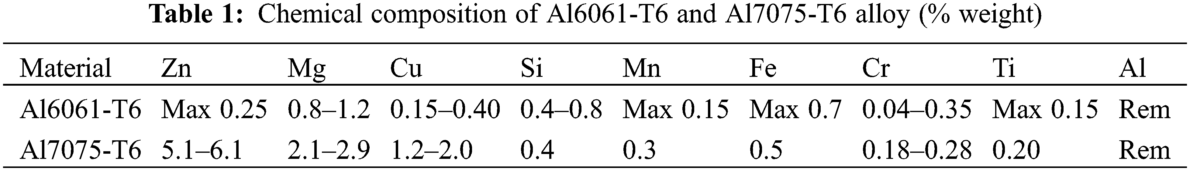
In order to achieve more strength along with less weight, Al6061-T6 and Al7075-T6 have been chosen as matrix material. These matrix materials contain alloying elements that mainly contribute to improving the mechanical properties through the effects of Zn, Cr, and Ti. The chemical composition of Al6061-T6 and Al7075-T6 is presented in Table 1. The foot bracket fractured due to the load fluctuations during the vehicle riding over the speed breakers. In particular, instead of applying more load behind the driver’s position, the fluctuation of the entire vehicle leads to meeting failure.
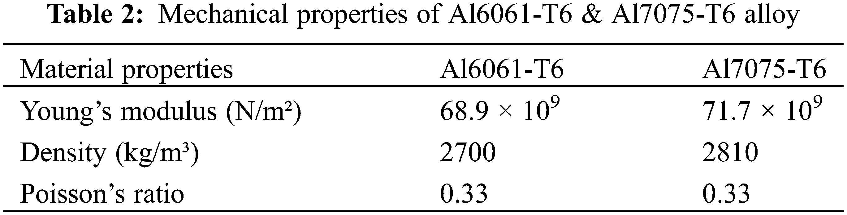
The existing model of the foot bracket in a two-wheeler is shown in Fig. 1. The collar neck area in the foot bracket panel is subjected to fracture due to load fluctuation in the running condition that leads to frequent failure of the foot bracket. It is not a component that is safe to use. The weight acting unexpectedly with the varied movements of the two-wheeler body while riding caused the failure. We are oblivious to the fact that a crack has formed in it. The material and design of this foot bracket panel may have been the cause of its unexpected breakdown. This is the primary motivation for starting this type of research study. As a result, it is critical to redesign the product. To overcome the failure, composites of Al6061-T6 and Al7075-T6 have been selected as replacement materials for the foot bracket in two-wheelers. The mechanical properties of Al6061-T6 and Al7075-T6 are shown in Table 2.
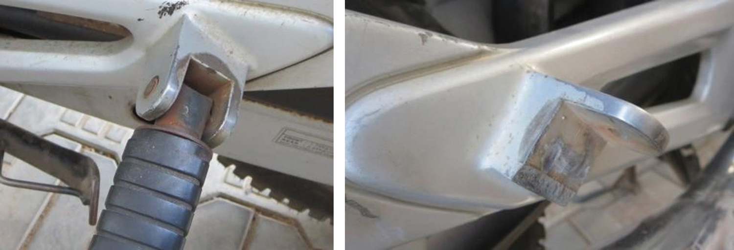
Figure 1: Fractured foot bracket
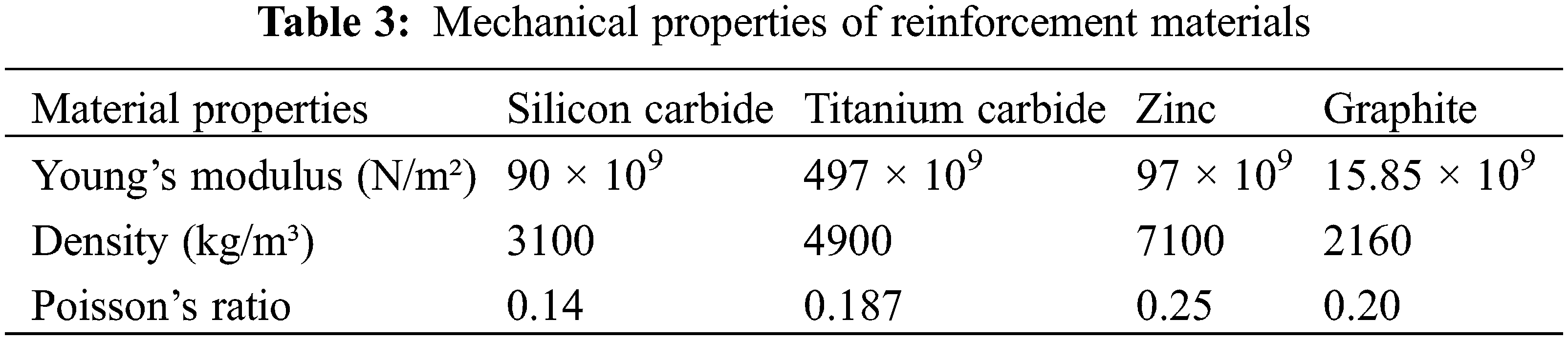
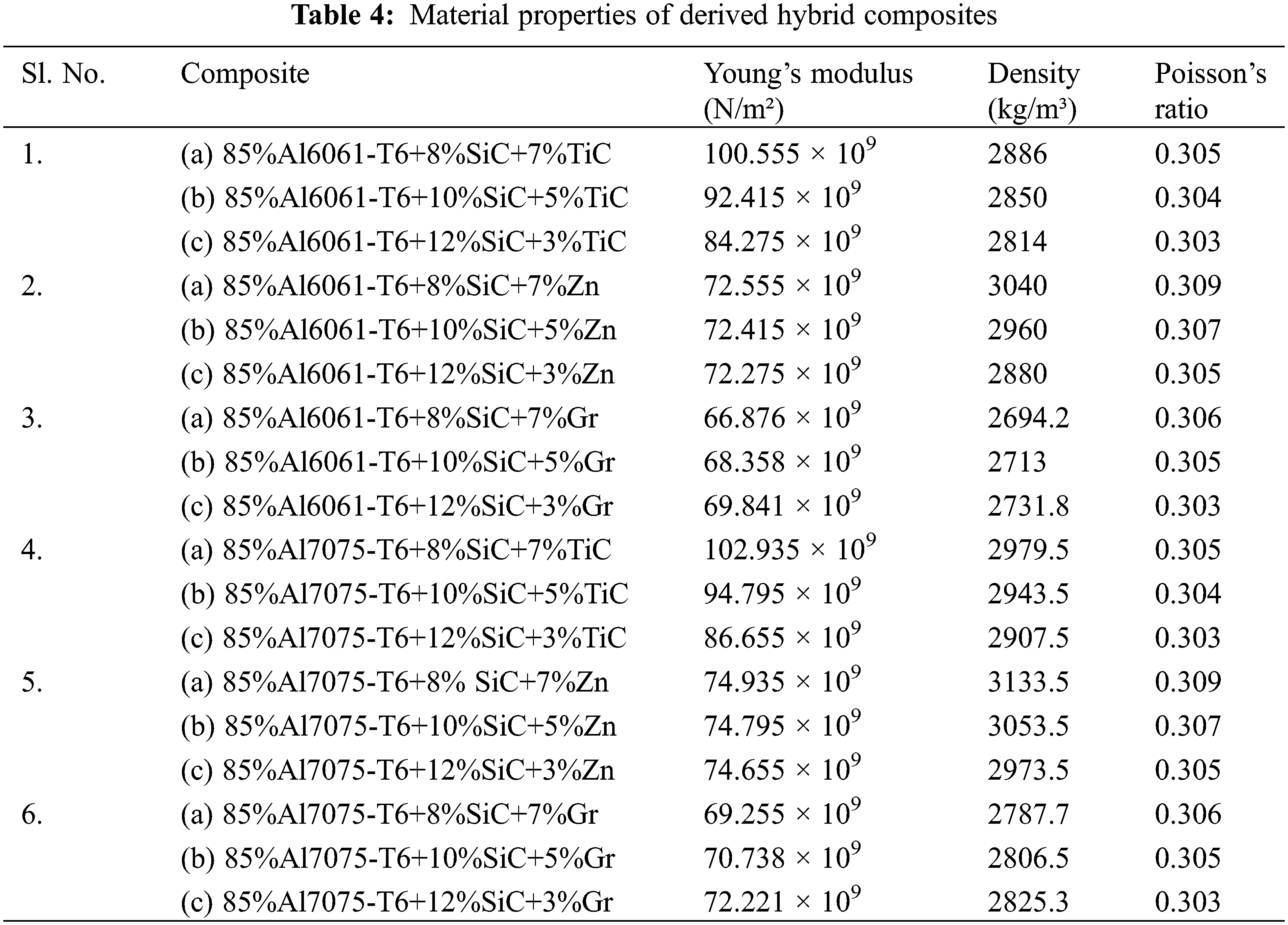
The addition of reinforcing material to the matrix can increase machinability, toughness, and hardness. As reinforcement materials, silicon carbide, titanium carbide, zinc, and graphite particles were chosen. Hybrid MMC refers to the layer-by-layer incorporation of these components into the matrix material. The properties of the reinforcement materials are shown in Table 3. The different volumes proportionate to the matrix material and reinforcement material chosen for the analysis are recorded in Table 4. The initial nine experiments are allotted for conducting analysis on Al 6061-T6 with different proportions of reinforcement. Similarly, the remaining nine experiments were conducted on Al 7075-T6. The contribution of aluminium alloy was fixed at 85% for both Al6061-T6 and Al7075-T6. The rest of the volume fraction can be accommodated by reinforcement particles like SiC with a percentage of 8–12% for both Al6061-T6 and Al7075-T6 and TiC, Zn, and Gr with a percentage of 3–7%, respectively.
2.1 Calculation of Hybrid Composite Properties
The hybrid composite material properties such as Young’s modulus, density, and Poisson ratio have been calculated by considering the material properties and contribution of volume percentage of reinforcement particles and matrix materials. The formulae for the calculation of hybrid composite material properties are presented in Eqs. (1)–(3).
where, Em = Young’s Modulus of Matrix; Er = Young’s Modulus of Reinforcement; Vm = Volume of matrix; Vr = Volume of Reinforcement. The calculated material properties for derived hybrid composite is listed below in Table 4.
2.2 Modeling and Analysis of Foot Bracket
The failure analysis was performed on the foot bracket of the “Yamaha Libero G5” two-wheeler, which is made of Aluminum alloy 6061 and was cracked owing to abrupt load changes during driving. As a result, we’ve taken this Al6061 as an existing material that can be cast again with the addition of SiC, TiC, and Zn reinforcements. In addition, Al7075, which is rich in titanium, can be used as a substitute for Al6061. The inclusion of Si and Ti carbides resulted in remarkable recrystallization material structure, toughness, and hardness, among other properties. Through solid solution strengthening, the addition of Mg to Al7075 has progressed good strain hardening. CREO Parametric software has been proposed to model the two wheeler foot bracket. The modified dimensions and modelling of certain components help to recreate the structure as a better alternative to the existing failure or fractured models. The different views of the CREO Parametric 2D model foot bracket represent the dimensions of the complete structure as shown in Fig. 2b. The force components and boundary conditions are clearly indicated as free body diagrams in Fig. 2a. The displacement of the screwed ends of this foot bracket panel has been constrained in both x, y, and z axes by applying the boundary conditions. The isometric projection of CREO Parametric 3D Modeled foot bracket as shown in Fig. 3 is further exploited for analysis.
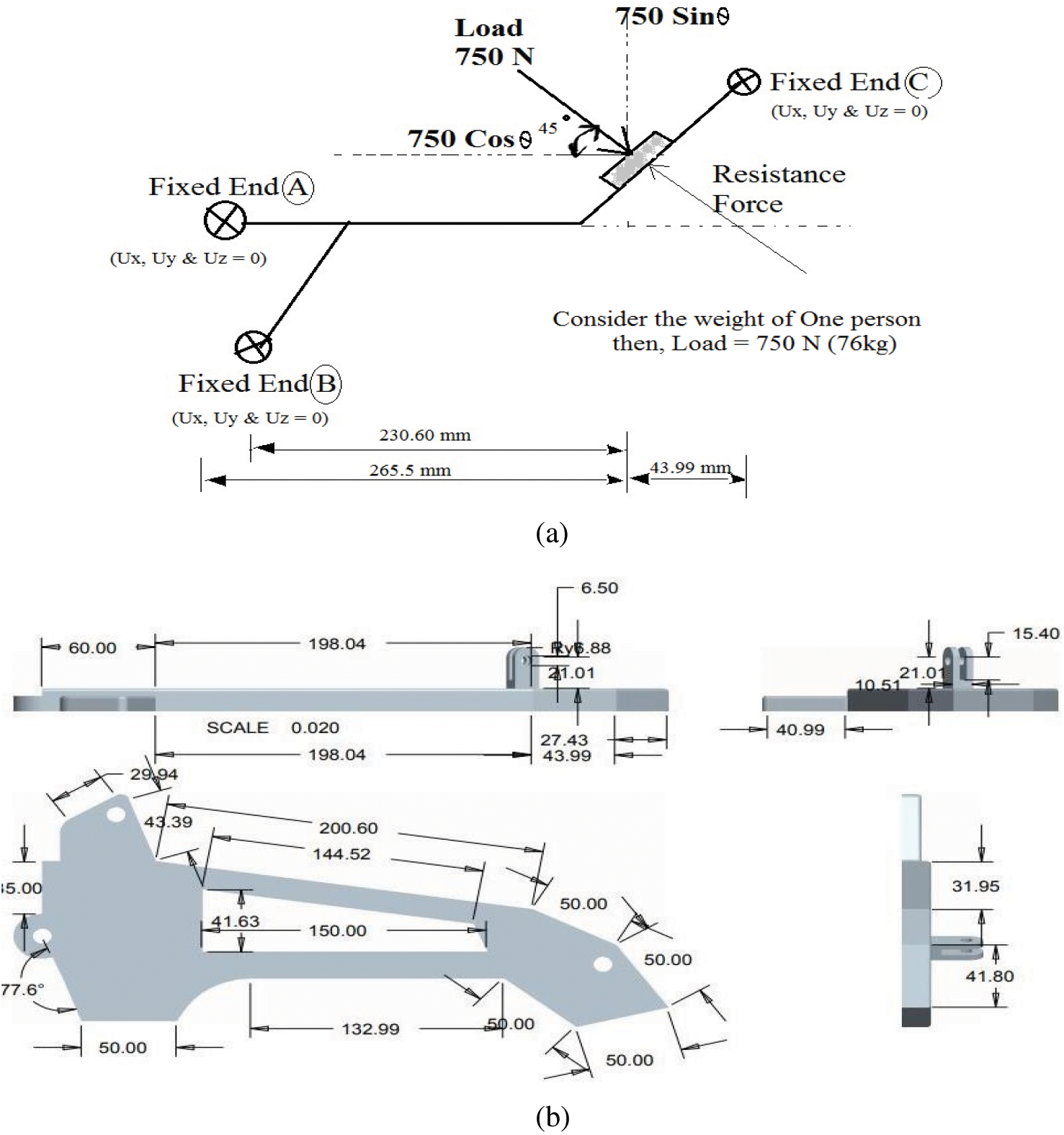
Figure 2: (a) Free body diagram of foot bracket (b) orthographic views of 2-dimensional modelled foot bracket (in mm)
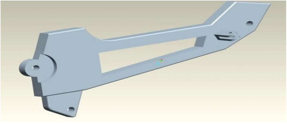
Figure 3: Isometric projection of Creo parametric 3D model foot bracket
The modelled foot bracket can be subjected to analysis with the help of ANSYS software. We have done our solid modelling part design by using the latest version of Creo Parametric only. The simulation part has been done by using ANSYS 15, and the post processing output images have been modified with the most recent version of ANSYS 15. The application of software is recommended for prediction of performance of the foot bracket before the application of workouts or real time production of certain components. To begin, the modelled foot bracket can be used to create simulations with their corresponding material properties and successive mesh generations. The determined values of each young’s modulus, density and poisons ratio as shown in Table 5 can be used for applying the material properties of the modelled foot bracket for the analysis. After the nomination of material models, a suitable finer mesh has been generated over the foot bracket solid model, as shown in Fig. 4. The stir cast composite that we created falls under the category of anisotropic material. The Young’s modulus and Poisson’s ratio of these hybrid composites were determined individually and used in the ANSYS APDL material models. The modelling was done with the CREO parametric solid modeller, and the simulation was done with ANSYS using the Solid brick 8 node element type. In ANSYS simulation software, the structural element model was selected using the structural solid layer construction method, with full integration and pure displacement type of element technology. The convergent mesh generation method was used to obtain more precise results in the quad or brick shape of the mesh volume. The 93894 modified or new elements, as well as 15515 nodes, were discovered during the shape testing.
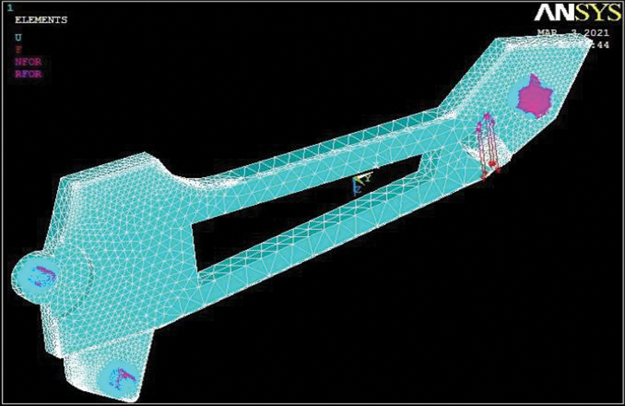
Figure 4: Meshed foot bracket model
After enactment of the element, material properties, and meshing of the modelled foot bracket, the boundary conditions were applied to both the screwed holes at the front side and rear side of the foot bracket panel. The displacement becomes zero at the fixed holes. It was observed in real time that the collar end of the foot bracket was treated as a sensitive location for fracture. It leads to frequent failures over fluctuating loads. Specific attention was given to the collar end of the foot bracket in terms of designing the diameter of the curve and arc-shaped structure with exceptionally fine dimensions. The Finite Element Analysis procedure was adopted for the purpose of finding the withstanding levels of bending moments and stresses with the assistance of changes in material compositions. So various hybrid metal matrix composite structures were planned to do analysis and simulations. The boundary conditions have been applied to this foot bracket structure in the form of the screwed-in end on both ends of the vehicle’s body chassis. The negative directional load is acting on the collar joint nodes of the foot bracket that was defined with the displacement function, which is not equal to zero. Because the load acting direction is not exactly perpendicular to the axis of the panel, there is a change of inclination between the datum axis of the foot bracket panel and the collar vertical. This collar arrangement has been allocated a 450 inclined position in this design. The 750 N loads, which is half the equivalent of the human pushing effort, are applied as downward motion over the meshed model of the foot bracket. After solving the intricate shaped foot bracket meshed model, nodal stress and nodal displacement have been computed under the principles of von Mises.
2.3 Mathematical Validation of Displacement and Stress
To validate results obtained from the ANSYS software, real time prototype-based mathematical modelling can be developed. By solving the partial differential equation with particular boundary value problems in two or three independent parameters, the standard mathematical modelling technique has been incorporated for these research findings. Let us consider the foot bracket as a simple cantilever beam having a total length of “l” metre that has been fixed at the bolted end as shown in Fig. 2. The load “W” Newton is acting at another free end of this cantilever type of foot bracket.
By using the double integration method of cantilever beam with the concentrated load is acting at the free end as displayed in Eq. (4).
where E-Young’s Modulus and I-Moment of Inertia.
To find the deflection of the intricate cross section of the foot bracket, the Eq. (4) can be rewritten as
The Centre of Gravity (C.G) of the foot bracket has been calculated by considering the horizontal and vertical distances as mentioned in the Figs. 2 and 3 and their value are (X,Y) = (150.38,70.159) mm. Using the centre of gravity, The value of Moment of Inertia (I) can be calculated and their value is I = 13.5 × 106 mm4. The deflection Eq. (5) can be reshaped as
For considering the entire length of the foot bracket, the deflection is maximum at the load acting end, then the Eq. (6) can be reduced to
Similarly, stress (σ) attained due to bending load over the foot bracket panel is given by
where, M – Bending Moment about the section neutral axis. (N/m2)
y – Perpendicular distance from the neutral axis to the point of intersection (m)
I – Moment of Inertia of the section area about the neutral axis (m4)
Then, substitute the expression of “y” in Eq. (8), then the stress equation is given by
The stress and displacement values of Eighteen HMMC obtained with the help of simulation are listed in Table 5. The corresponding simulation illustrations are exhibited in Figs. 5 and 6. From the simulation outcomes, it is apparent that the composites with the proportionate amount of added reinforcement for Al6061-T6 and Al7075-T6 are beneficial for providing reasonable values of stresses and displacements.
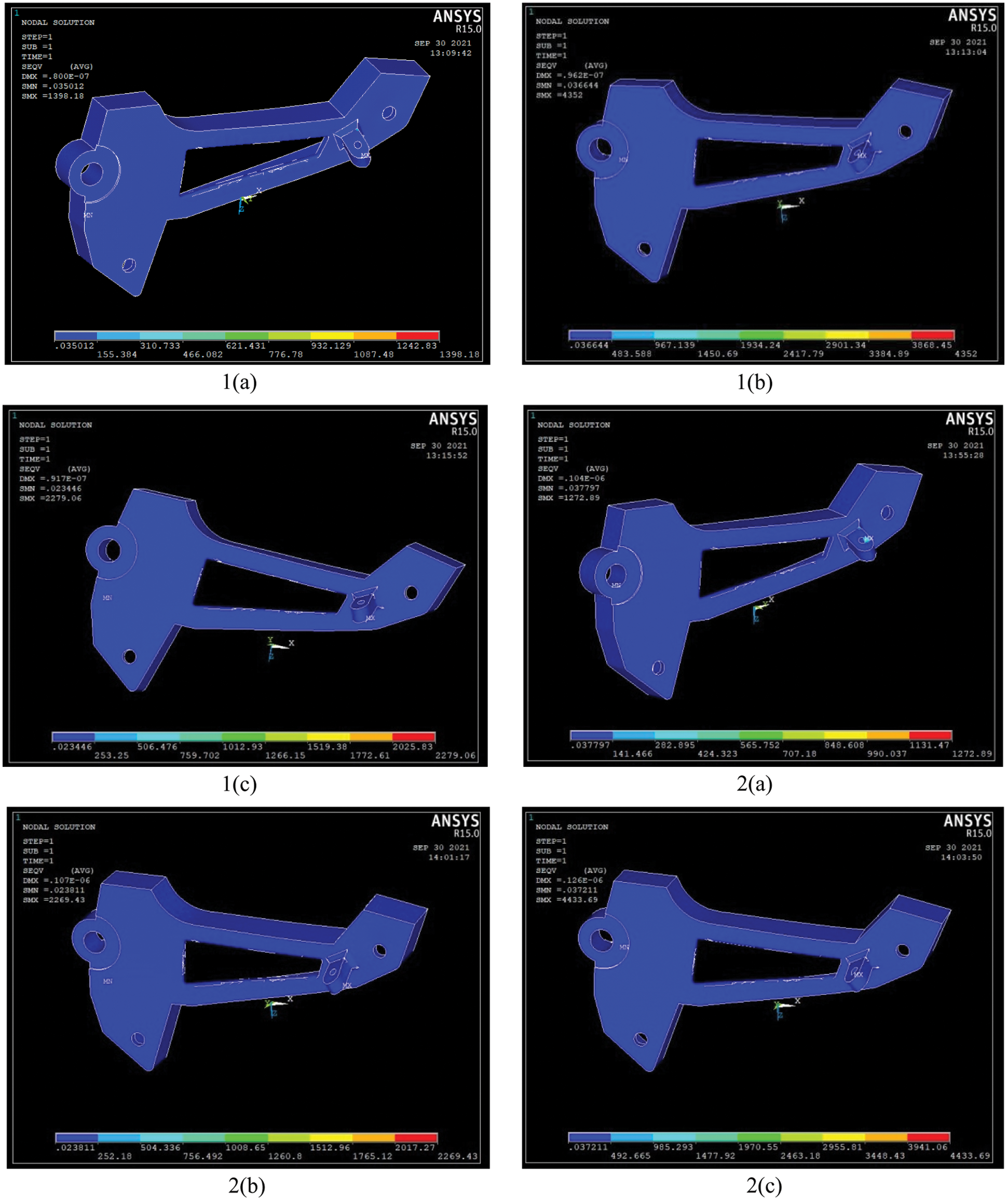
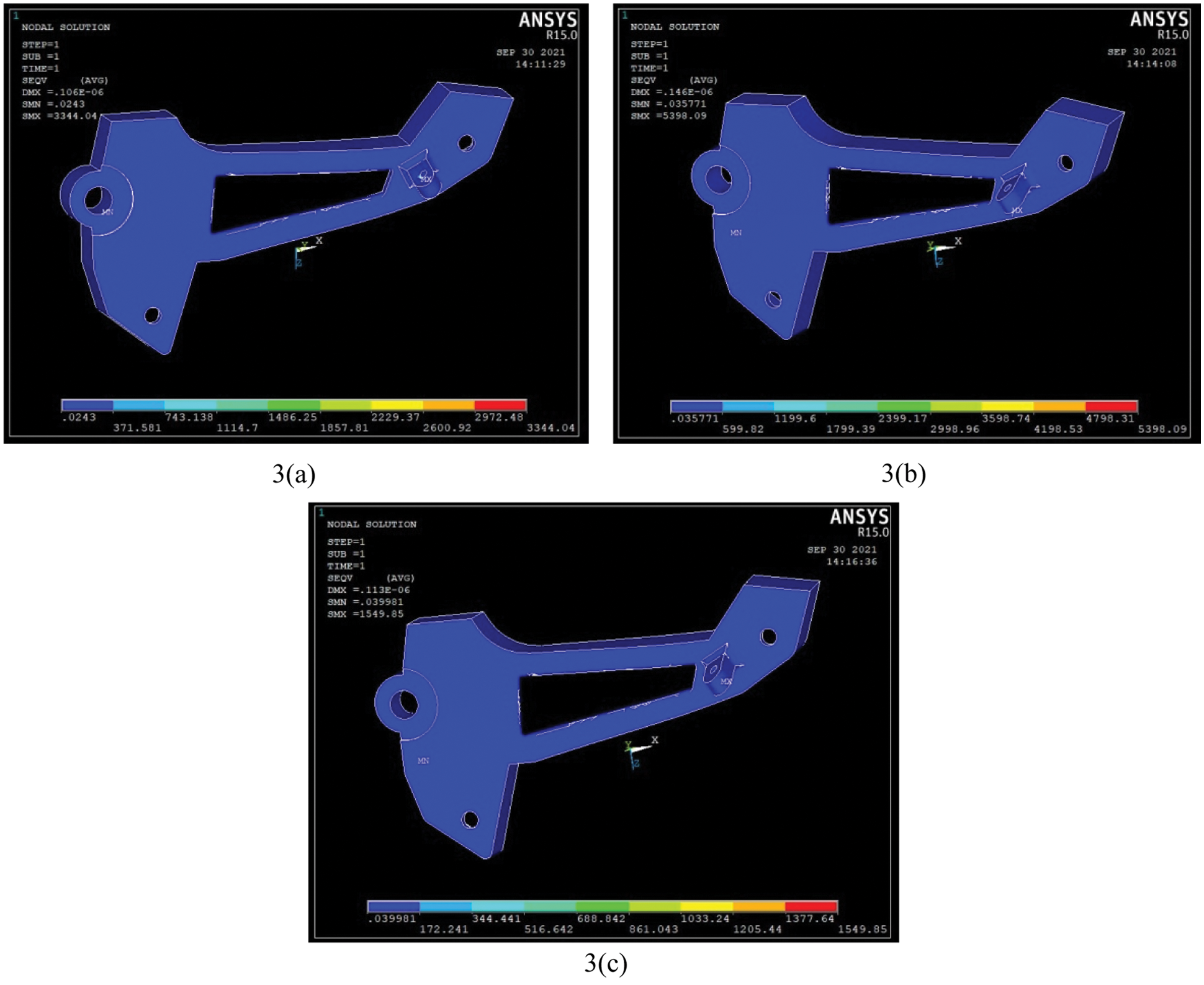
Figure 5: Simulation illustrations for Al6061-T6 HMMC using ANSYS APDL 14.5 (Experiment numbers from 1(a) to 3(c) of Table 5)
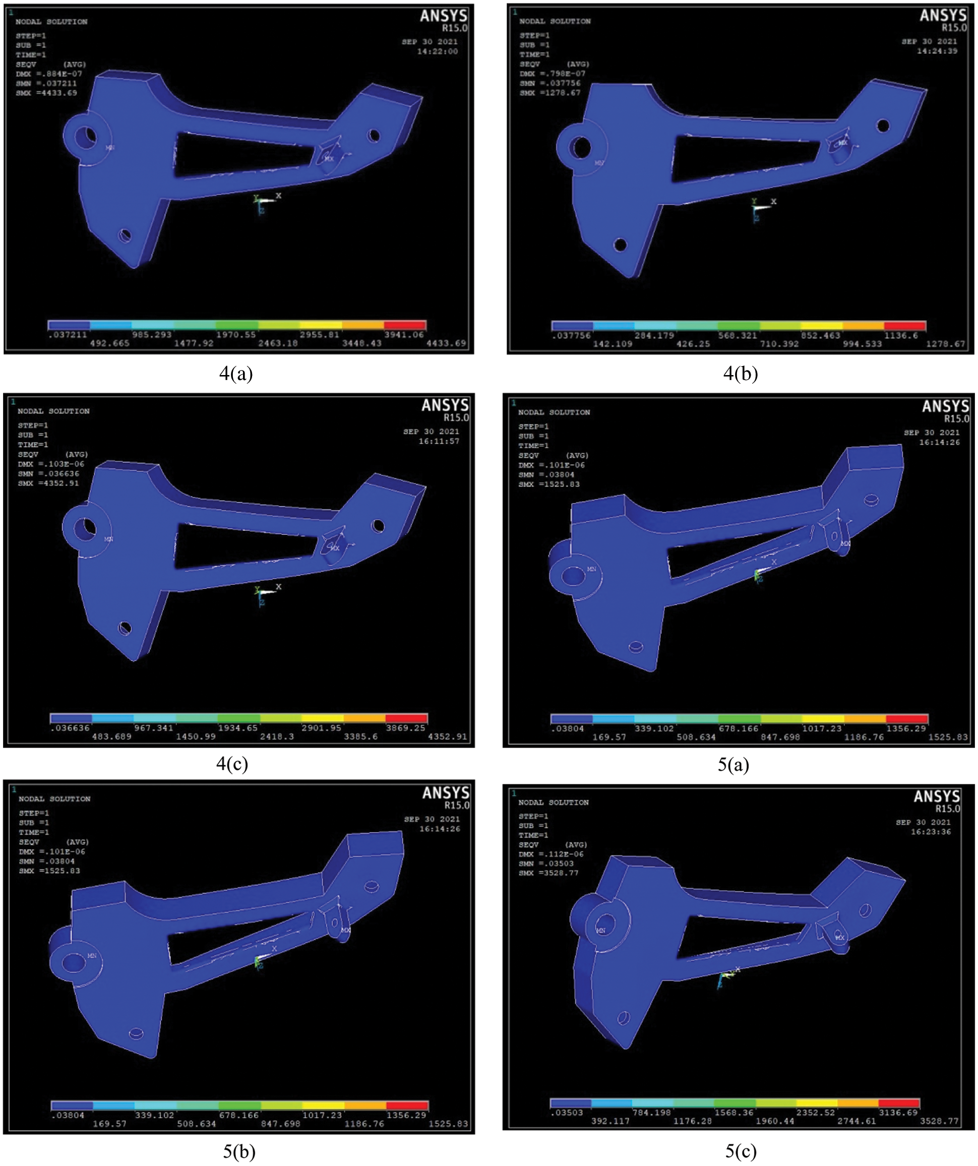
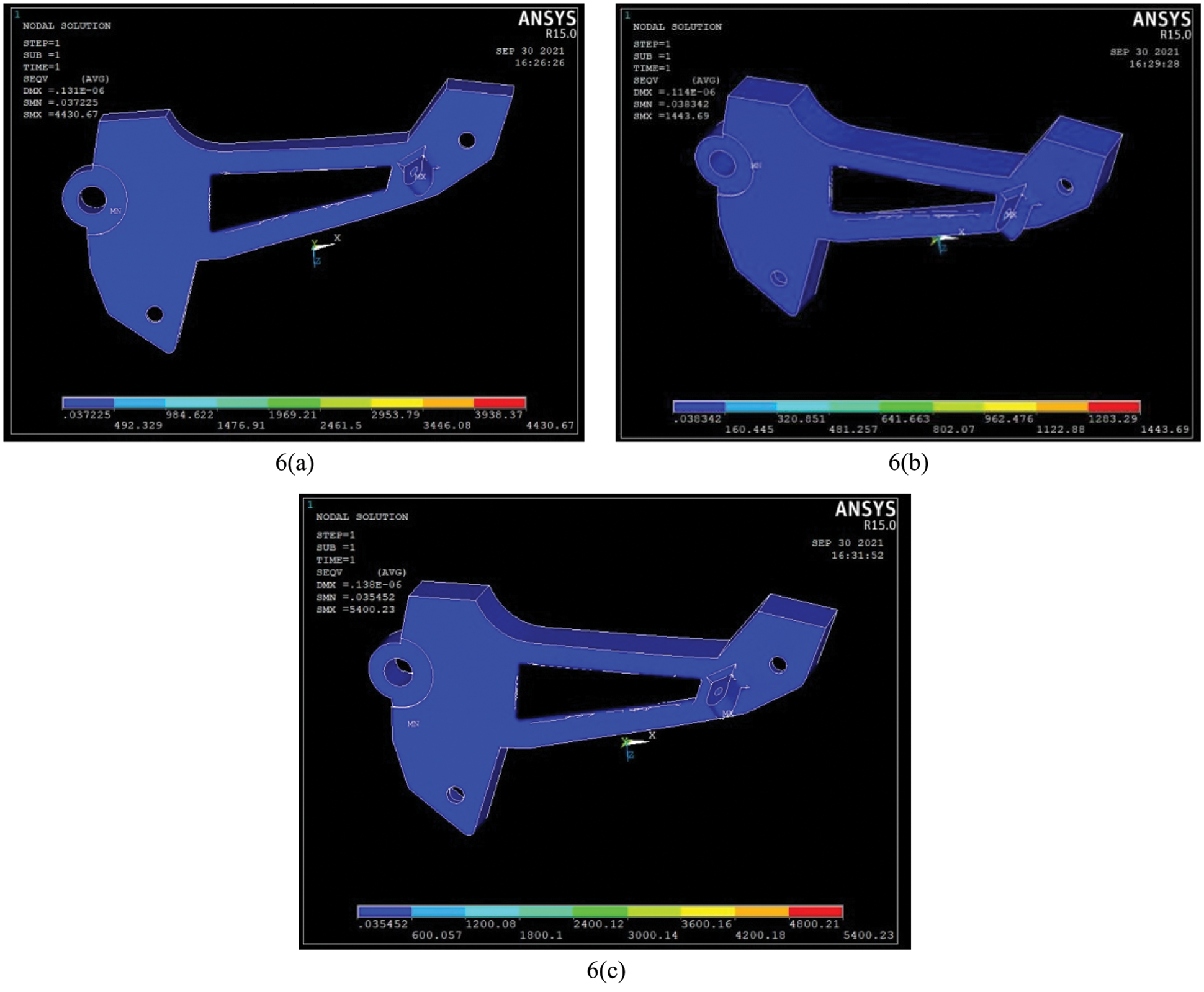
Figure 6: Simulation illustrations for Al7075-T6 HMMC using ANSYS APDL 14.5 (Experiment Numbers from 4(a) to 6(c) of Table 5)
The stress obtained from the ANSYS simulation results of each composite material combination is mentioned in Table 5. It is nothing but the predictive stress values of each weight percentage of composites, either they can withstand or not, during the higher load conditions. The failure happened due to the higher load acting over it during the hurdle-wise riding of the vehicle. The failure is due to sudden or gradual load applied and it has unpredicted material properties either as an alloy form or mixture. The deformations and bending moments are very essential for these linear elasticity failure applications. The bending of the beam in the foot bracket can withstand higher load conditions during the riding of a motorcycle. Material properties are the major influencing factor which we have considered for the improvement of linear elasticity. That is the reason we have determined the various mixtures of composites and their predicted stresses and displacements. The Maximum distortion energy theory has been considered by the values of von Mises stress in Ansys finite element modelling. The yielding of a component (foot bracket) as a result of bending moment with respect to the screwed boundary conditions.
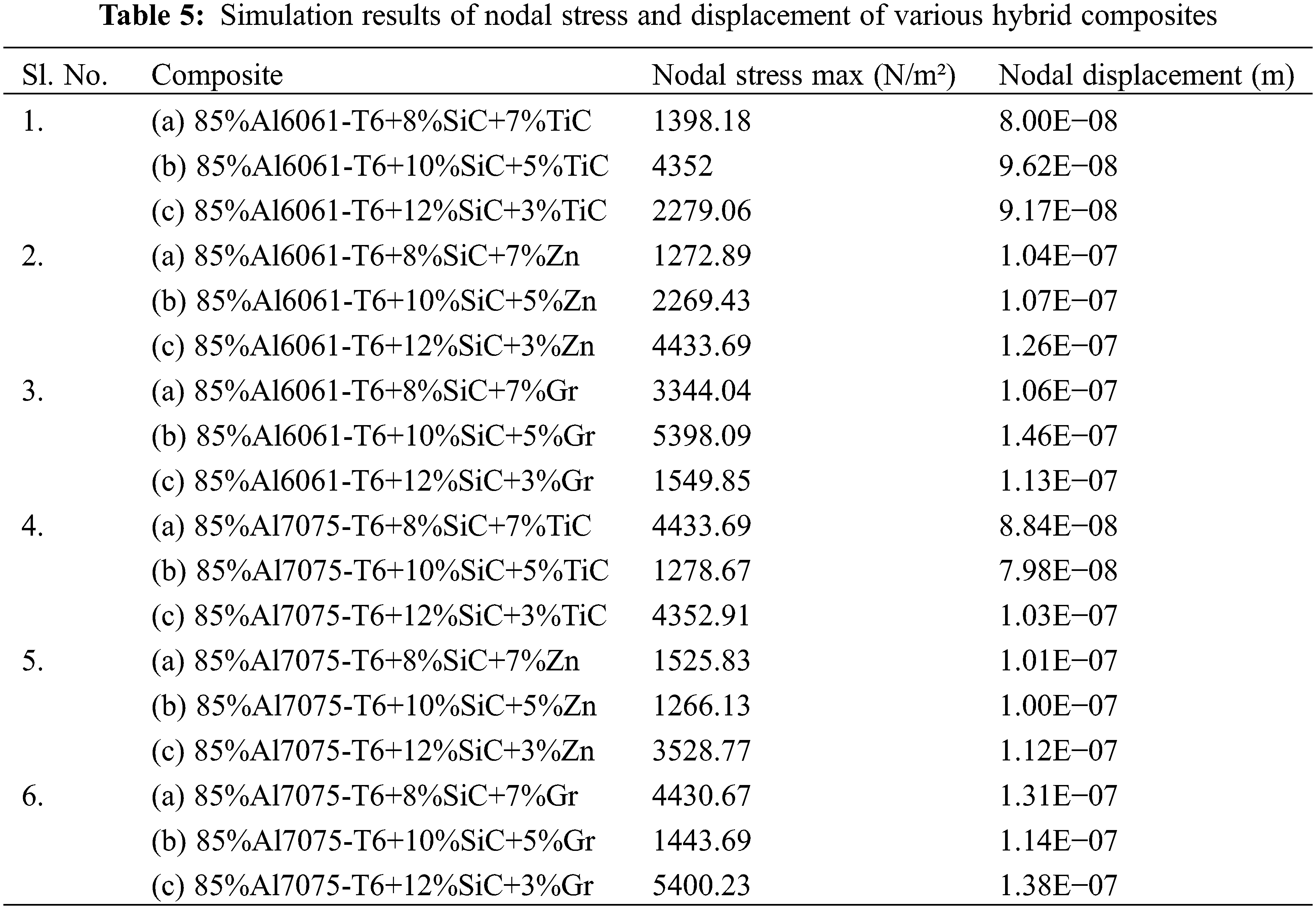
The results obtained from the simulation software are depicted in the graph (Fig. 7) to aid comprehension. It is observed that there is a continuous uneven increment of stress and displacement for Al6061-T6 HMMC. Changes in the geometrical shape of any component or part will only result in changes in its stress values. But the deformation and strain can be changed drastically with respect to the material changes. Material properties are important data to define the material structure and its strength. It is confirmed that during the preparation of anisotropic composite material, the stress levels can be varied and it depends on both geometrical changes and reinforcement additions towards MMC’s. By considering Al6061 hybrid composite form, the 10–12% of SiC and 5–7% Zn addition can withstand more stresses due to the nodal form acting on the collar of the foot bracket panel. Al7075 contains an alloying element of 5–6% Zn and minor Ti inclusions which increase the higher stress withstanding capacity compared with Al6061. Furthermore, the incorporation of SiC and graphite particulate brittle reinforcements improves the ability to withstand stresses and displacements. The higher stress that was observed from the simulative prediction is 5400.23 N/m2 for the composite material form of 85%Al7075+12%SiC+3%Gr. In addition, the higher value of stress was obtained as 5398.09 N/m2 for the Al6061+10%SiC+5%Gr composite form. Based on these results, the 15% SiC and Graphite additions with 85% of matrix alloy formation has delivered the good results. Their consistent nodal displacements are also 1.38E−07 and 1.46E−07 m, respectively.
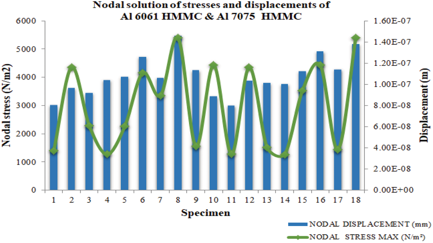
Figure 7: Comparison of simulation outcomes of Al6061HMMC & Al7075HMMC
The combination of matrix and reinforcements has contributed to the outstanding performance in terms of maintaining maximum stress and minimum displacement. It was achieved with the combined contribution of SiC, TiC, and graphite reinforcement particles. The combination of these reinforced particles in the metal matrix composite improved the strength, stiffness, and hardness (Atrian et al. [2]) of the foot bracket that lead to it acting as a fracture shield.
Out of 18 HMMC, two HMMC have been selected for validation of simulation outcome of displacement value with the mathematical models, and the results are listed in Table 6. It is noticed (Table 7) that the percentage of variation can be identified with the least difference for the concerned readings of the composite Al6061-T6 and Al7075-T6 composites. Hence, the simulated results are sufficient to substantiate the stress and displacement values. The validation or comparison of displacement function simulation results can be done using simple mathematical modelling. By using the simple beam deflection equation, we were able to model and simulate the cantilever type and its bending moments as shown in Eqs. (6) and (7). As shown in Tables 5 and 6, the average values of mathematical and simulated displacements were compared to the least variation. The self-damping capacity of Zinc (Zn) and hardness improvement by the addition of Graphite (Gr) particles are the root causes of getting these nodal displacements in the range of 6.43E−06 m to 9.44E−06 m for the composite of Al6061-SiC-Zn. Then it can withstand the highest displacement during the fluctuating load conditions and irrelevant load acting directions. There is no such elevation that was observed using TiC as reinforcement.
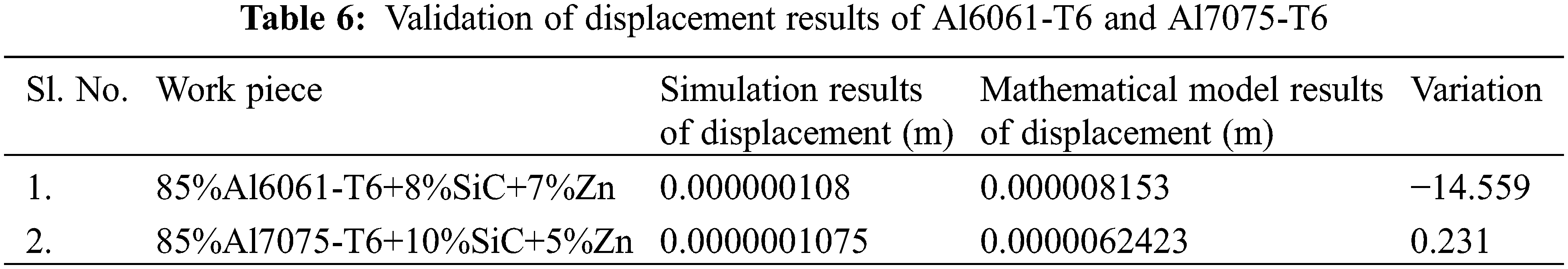
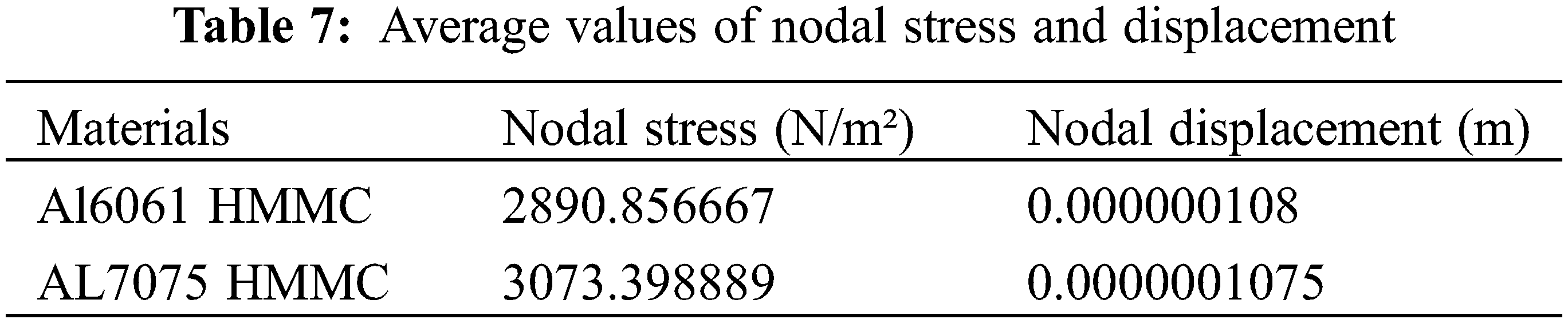
Fig. 8 depicts a comparison of the average stresses of Al6061-T6 and Al7075-T6 HMMC. It is the Al7075-T6 HMMC that holds the maximum stress when compared with the Al6061-T6 HMMCs. The amount of magnesium present in the Al7075-T6 alloy along with the reinforcement particles has increased the solid solution strengthening. It also improved their strain hardening ability. Hence, these effects principally contribute to withstanding the maximum stress and minimum displacement. As a future scope with the reference of this manuscript, the new design can be implemented with fewer geometric values and more strength might be incorporated.
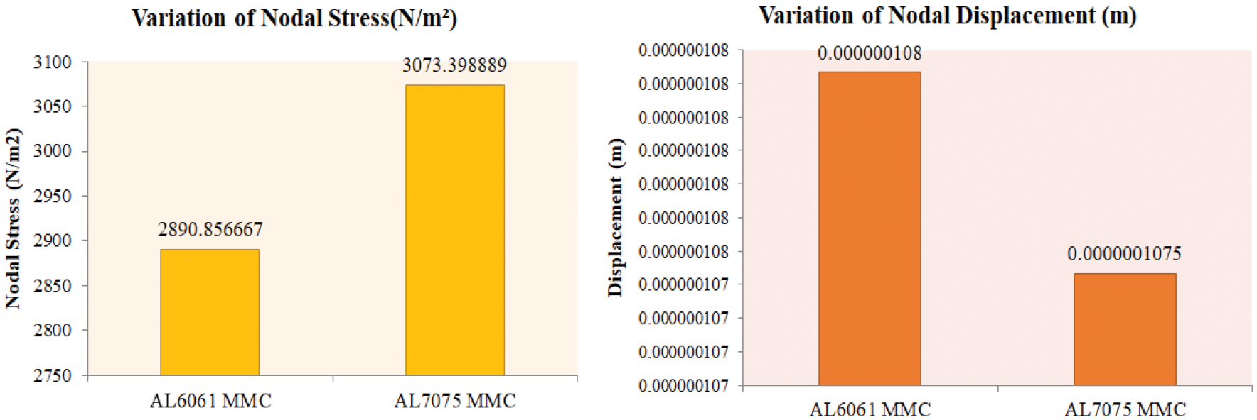
Figure 8: Comparison of nodal stresses and displacements of Al6061-T6 and Al7075-T6 HMMC
The comparison has made among the average values of Nodal Stress and Displacement of Al6061 HMMC and Al7075 HMMC’s shown in Table 7 represents that the higher average value of withstanding stress of 3073.398 N/m2 has been attained by the Al7075 HMMC’s. This was mentioned in Fig. 8 with a 16% improvement in Al7075 HMMC compared with the Al6061 HMMC. Likewise, the lower average of displacements has been observed better in Al7075 HMMC.
By exercising the simulation and mathematical modelling of two-wheeler foot, the following conclusions have been arrived at:
• Modeling and analysis of the two-wheeler foot bracket was carried out using CREO and ANSYS Software.
• According to the simulation results, the composite of 85% Al7075-T6+12%SiC+3% TiC can withstand maximum stress of 5400.23 N/m2 and minimum displacement of 46 × 10−07 m. It was achieved with the combined contribution of SiC and TiC reinforcement particles with Zn inclusions. The combination of SiC and TiC reinforced particles in the metal matrix composite improved the strength, stiffness, and hardness of the foot bracket, which led to its acting as a fracture shield.
• The simulated model is treated as an accurate Simulation results have been validated with the developed mathematical model that provides the least difference of 0.231%.
• The identified combination of 85%Al7075-T6+12%SiC+3%TiC Hybrid Metal matrix Composite and Al6061+10%SiC+5%Gr HMMC has provided better structural stability that can withstand the load fluctuations on the foot bracket.
Acknowledgement: The authors would like to thank their research supervisors, technicians for their esteemed guidance and technical supports throughout the research. The author would also wish to acknowledge the co-authors for supporting this research project.
Funding Statement: The authors received no specific funding for this research.
Conflicts of Interest: The authors declare that they have no conflicts of interest to report regarding the present study.
1. Agostoni, S. S., Cheli, F., Leo, E., Pezzola, M. E. (2012). Methodology to design a vibration absorption footplate for motorcycle application: From phenomena investigation to prototype performance evaluation. Mechanical Systems and Signal Processing, 30(5), 296–305. DOI 10.1016/j.ymssp.2011.11.017. [Google Scholar] [CrossRef]
2. Atrian, A., Majzoobi, G. H., Enayati, M. H., Bakhtiari, H. (2014). Mechanical and microstructural characterization of Al7075/SiC nanocomposites fabricated by dynamic compaction. International Journal of Minerals, Metallurgy, and Materials, 21(3), 295–303. DOI 10.1007/s12613-014-0908-7. [Google Scholar] [CrossRef]
3. Ravi, B., Jeyan, J. V. M. L., Basithrahman, A., Talasila, E. R., Abirami, S. (2021). Comparative analysis on mechanical properties of Al 6061 and Al 7075 cross matrix composites. In: Prakash, C., Krolczyk, G., Singh, S., Pramanik, A. (Eds.Advances in metrology and measurement of engineering surfaces. Lecture notes in mechanical engineering. Singapore: Springer. [Google Scholar]
4. Balaji, V., Sateesh, N., Hussain, M. M. (2015). Manufacture of Aluminium Metal Matrix Composite (Al7075-SiC) by Stir casting technique. Materials Today: Proceedings, 2(4–5), 3403– 3408. DOI 10.1016/j.matpr.2015.07.315. [Google Scholar] [CrossRef]
5. Basak, A. K., Pramanik, A., Prakash, C. (2019). Deformation and strengthening of SiC reinforced Al-MMCs during in-situ micro-pillar compression. Materials Science and Engineering: A, 763(6), 138141. DOI 10.1016/j.msea.2019.138141. [Google Scholar] [CrossRef]
6. Bejaxhin, B. H. A., Paulraj, G., Prabhakar, M. (2019). Inspection of casting defects and grain boundary strengthening on stressed Al6061 specimen by NDT method and SEM micrographs. Journal of Materials Research and Technology, 8(3), 2674–2684. DOI 10.1016/j.jmrt.2019.01.029. [Google Scholar] [CrossRef]
7. Bejaxhin, B. H. A., Paulraj, G., Aravind, S. (2020). Influence of TiN/AlCrN electrode coatings on surface integrity, removal rates and machining time of EDM with optimized outcomes. Materials Today: Proceedings, 21, 340–345. DOI 10.1016/J.MATPR.2019.05.459. [Google Scholar] [CrossRef]
8. Bejaxhin, B. H. A., Paulraj, G., Jayaprakash, G., Vijayan, V. (2020). Measurement of roughness on hardened D-3 steel and wear of coated tool inserts. Transactions of the Institute of Measurement and Control, 43(3), 528–536. DOI 10.1177/0142331220938554. [Google Scholar] [CrossRef]
9. Hutchinson, B. (2015). Critical assessment 16: Anisotropy in metals. Materials Science and Technology, 31(12), 1393–1401. DOI 10.1179/1743284715Y.0000000118. [Google Scholar] [CrossRef]
10. Campbell, F. C. (2010). Introduction to composite materials structural composite materials, vol. 1, pp. 1–29. ASM International. [Google Scholar]
11. Aboelseoud, M. A., Myers, J. J. (2019). Flexural behavior of hybrid composite beam (HCB) bridges. Hindawi Advances in Materials Science and Engineering, 13(1), 1–13. DOI 10.1155/2019/1690512. [Google Scholar] [CrossRef]
12. Meenakshi, C. M., Krishnamoorthy, A. (2019). Study on the effect of surface modification on the mechanical and thermal behaviour of flax, sisal and glass fiber-reinforced epoxy hybrid composites. Journal of Renewable Materials, 7(2), 153–169. DOI 10.32604/jrm.2019.00046. [Google Scholar] [CrossRef]
13. Prithivirajan, R., Sivagami, S. M., Narayanasamy, P. (2015). Characterization of aluminium alloy 2024-T351/ different hybrid ratio of SiC and B4 C fabricated by friction stir processing. International Journal of Applied Engineering Research, 10(57), 444–448. [Google Scholar]
14. Rao, K. M. M., Rao, K. M., Prasad, A. V. R. (2010). Fabrication and testing of natural fibre composites: Vakka, sisal, bamboo and banana. Materials and Design, 31(1), 508–513. DOI 10.1016/j.matdes.2009.06.023. [Google Scholar] [CrossRef]
15. Golushko, S. (2018). Mathematical modeling and numerical optimization of composite structures. In: Maalawi, K. Y. (Ed.Optimum composite structures. London: IntechOpen. [Google Scholar]
16. Sivagami, S. M., Meignanamoorthy, M., Vijay, T. R., Punitharani, K., Ravichandran, M. (2020). Effect of iron oxide and graphite reinforcement on mechanical properties of AA7075 hybrid composite. Materials Today: Proceedings. DOI 10.1016/j.matpr.2020.10.863. [Google Scholar] [CrossRef]
17. Thiagarajan, C., Lakshminarayanan, N., Anand, A., Santhosh, M. N., Anderson, N. J. (2020). Investigation and analysis of properties of magnesium alloy for suitability to electric vehicle components. IOP Conference Series Materials Science and Engineering, 993(1), 012007. DOI 10.1088/1757-899X/993/1/012007. [Google Scholar] [CrossRef]
18. Zouari, W., Assarar, M., Chilali, A., Rezak, A., Kebir, H. (2019). Numerical modelling of the transient hygroscopic behavior of flax-epoxy composite. Journal of Renewable Materials, 7(9), 839–853. DOI 10.32604/jrm.2019.06773. [Google Scholar] [CrossRef]
19. Kongkitkul, W., Musika, N., Tongnuapad, C., Jongpradist, P., Youwai, S. (2014). Anisotropy in compressive strength and elastic stiffness of normal and polymer-modified asphalts. Soils and Foundations, 54(2), 94–108. DOI 10.1016/j.sandf.2014.02.002. [Google Scholar] [CrossRef]
 | This work is licensed under a Creative Commons Attribution 4.0 International License, which permits unrestricted use, distribution, and reproduction in any medium, provided the original work is properly cited. |