| Fluid Dynamics & Materials Processing |
DOI: 10.32604/fdmp.2022.017920
ARTICLE
A Genetic Algorithm for Optimizing Yaw Operation Control in Wind Power Plants
Xi’an Traffic Engineering Institute, Xi’an, 710300, China
*Corresponding Author: Lisha Shang. Email: shanglisha313@126.com
Received: 16 June 2021; Accepted: 22 September 2021
Abstract: A genetic algorithm is proposed to optimize the yaw control system used for the stable and efficient operation of turbines in wind power plants. In particular, the factors that produce yaw static deviation are analyzed. Then, the sought optimization method for the yaw static deviation of the wind turbine is implemented by using a lidar wind meter in the engine room in order to solve the low accuracy problem caused by yaw static deviation. It is shown that fuzzy control can overcome problematic factors such as the randomness of wind direction and track the change of wind direction accurately. Power control implementation is simple, as only the voltage and current of the generator need to be measured.
Keywords: Genetic algorithm; yaw control system; power control; the control strategy
Wind energy is the fastest growing clean energy among renewable energy, and the development and utilization of wind energy has become a hot spot for new energy investment. As one of the core components of the wind turbine control system, the yaw control system plays a very important role in the safe, stable and efficient operation of the wind turbine. Therefore, it is necessary to study the yaw control system of wind turbines. The yaw system is a set of devices that make the wind turbine automatically orient to the wind direction, including drive motors, gear combinations, control system devices, and wind measurement devices [1]. The wind measuring device is basically above the rear of the nacelle, and the wind vane and the normal direction of the impeller are required to be consistent for accurate measurement. The final wind direction and the angle of the normal direction of the impeller are the yaw angle. The yaw system is a unique servo system of the wind turbine, which mainly implements two functions: one is to keep the impeller normal to the wind direction; the other is to untie the cable when the number of turns in the same direction in the nacelle exceeds the set value to avoid damage. Its working principle: how the wind direction changes, the signal is obtained by the sensor, and then the signal is sent to the closed-circuit controller controlled by the yaw motor. The yaw direction and angle are determined by the processor, so that the normal line of the impeller is consistent with the wind direction, and the wind direction is compared. When yaw, a large gyro torque is generated, so the motor is connected with the reducer to reduce the motor speed, so that the yaw torque acts on the large gear of the rotating body, and then pushes the yaw wind wheel to the wind. After this process is completed, the impeller normal line is consistent with the wind direction, the wind direction sensor signal disappears, the yaw motor stops, and the yaw is completed [2,3].
At present, scholars have studied the optimization of wind turbine yaw control strategy from the aspects of dynamics, control technology, data analysis, etc., mainly to solve the influence of yaw control performance error on yaw error, but there are few studies on yaw static deviation optimization. This article analyzes the factors that produce yaw static deviation. Taking the power generation performance of wind turbines as the optimization goal, the nacelle lidar anemometer is used to propose a wind turbine yaw static deviation optimization method to solve the problem of low wind measurement accuracy of wind turbines. In order to achieve the efficient tracking of wind direction by the wind turbine, improve the power generation efficiency of the unit, and ensure the reliability of the unit, Lakshmanan et al. [4] suggested using genetic algorithm to develop a Bwer detection algorithm to adjust the fuzzy set. The run-time algorithm uses the tuning information generated by the genetic algorithm to distinguish between bwers and non-bwers, and assigns confidence estimates to its detection. A genetic algorithm used to adjust the basis of fuzzy rules of Bwer algorithm is described. The use of genetic algorithms to adjust the paradigm of fuzzy rules is a very general and useful rule. It can be used to improve the performance of other weather detection algorithms. The example enables you to change the behavior of the run-time algorithm based on the locale and/or the end user. The paradigm applied to Bwer’s algorithm can adjust the use of forecasters and neural network algorithms. Jones et al. [5] proposed the use of genetic algorithms to report results to software-based software, which used evolutionary strategies to explore complete conformational flexibility of ligands with partial flexibility of proteins, and meet the basic requirement that ligands must loosely bind water. According to the five test systems and the experimental data show good agreement, the design of the algorithm provides an in-depth understanding of the molecular recognition mechanism [5]. Sun et al. [6] proposed a power prediction model that optimizes the yaw Angle to minimize the overall wake shock of wind turbines. The Power model considers the wake-up effect of artificial neural network (ANN), that is why it is called ANN-WAKE-POWER model. The model can estimate the total power generated by a wind turbine for a given wind speed, direction and yaw Angle. A case study has been completed to illustrate the modeling process. Experimental data from five types of wind turbines operating wind farms have been used to train and evaluate models. The ANN-WAKE-POWER model has been proved to be effective in estimating Power generation which strikes a good balance between computational cost and accuracy. Then, using the model to optimize the yaw angle through genetic algorithm and the optimized yaw angle strategy, the total power ratio of the wind turbine in all the involved directions can reach 0.96. For a group of wind turbines, the optimal yaw control strategy for each wind turbine is different. Finally, it is worth noting that in order to achieve the good performance of the Ann-Wake-Power model, sufficient input data should be used during the training process [6].
2.1 Determination of Yaw Control Strategy
The power absorbed by the impeller of the wind generator from the air source can be expressed as follows: P = K ° C ° V3cosβ , where, P is the power obtained from the wind energy by the impeller of the wind turbine; K is determined by the air density and the rotating area of the impeller of the wind generator; C is the power correlation coefficient of wind turbine impeller; β is the angle formed between the normal direction of the impeller of the wind turbine and the wind direction, that is, the relative wind direction. Obviously, the power is the maximum when the wind speed is β = 0°, and the cosβ value near β = 0° does not change much. In general, it is required that the power obtained by the wind turbine should be greater than 95% of the maximum absorbable power when the wind speed is the same, β can be in the range of (−15°, 15°). Therefore, when designing the wind direction sensor, it is necessary to meet the β > 15° or β < −15° range to obtain the corresponding output signal. The yaw control signal of the controller is provided by the wind direction sensor. Due to the downwind direction, it is susceptible to a variety of destructive factors, and its own design direction finding accuracy also has certain shortcomings. The signal is not ideal, and the accuracy of the wind is low from an economic point of view. This article gives the changes in the internal wind that within the scope of fuzzy control, the control algorithm does not need to use wind sensors in the power range of small wind power [7].
2.2 Design of Yaw Fuzzy Control Model
Fuzzy control does not require precise mathematical models. It is not affected by nonlinear factors, can integrate expert knowledge efficiently, and has good dynamic performance and robustness. The turbine system achieves ideal control effects in terms of maximum wind energy capture of the unit, generator speed tracking monitoring, maximum power capture of the unit and wind energy robustness.
(1) Determine the structure of the fuzzy controller
According to the actual situation of the controlled object, the fuzzy controller determines the form and quantity of input variables and output variables. In general, the input variable is the error between the output variable and the given variable and the error rate of change, which is usually expressed by E (or E) and Ec (or EC). The output variable is the change of the controlled object variable, which is usually represented by Y. In this article, a fuzzy yaw control model with double input and single output is proposed. The input quantity is the deviation E and the change rate EC between the theoretical rotation Angle and the actual Angle measured by the wind measuring device. The output is the Angle control quantity u of the yaw control system. Its structure is shown in Fig. 1.
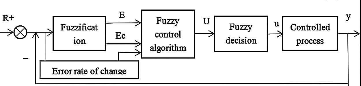
Figure 1: System block diagram of a fuzzy controller
(2) Ambiguity of input and output variables
According to the design method of the fuzzy controller, the domain of the input language variables E and is quantified into 13 levels, namely According to the design method of the fuzzy controller, the domain of the input language variables E and is quantified into 13 levels, namely. Its fuzzy subset A, B = {NB, NM, NS, ZE, PS, PM, PB}, which respectively represent {negative large, negative medium, negative small, zero, positive small, middle, positive large}. Set the fuzzy subset of output language variable (control variable change)U:C = {NB, NM, NS, ZE, PS, PM, PB}, the domain Z of U is also divided into 13 levels, namely: Z = { − 6, − 5, − 4, − 3, − 2, − 1, 0, 1, 2, 3, 4, 5, 6}. The triangle membership function has strong sensitivity and high resolution, so the fuzzy subsets of E, Ec and U in this paper all adopt the triangle membership function.
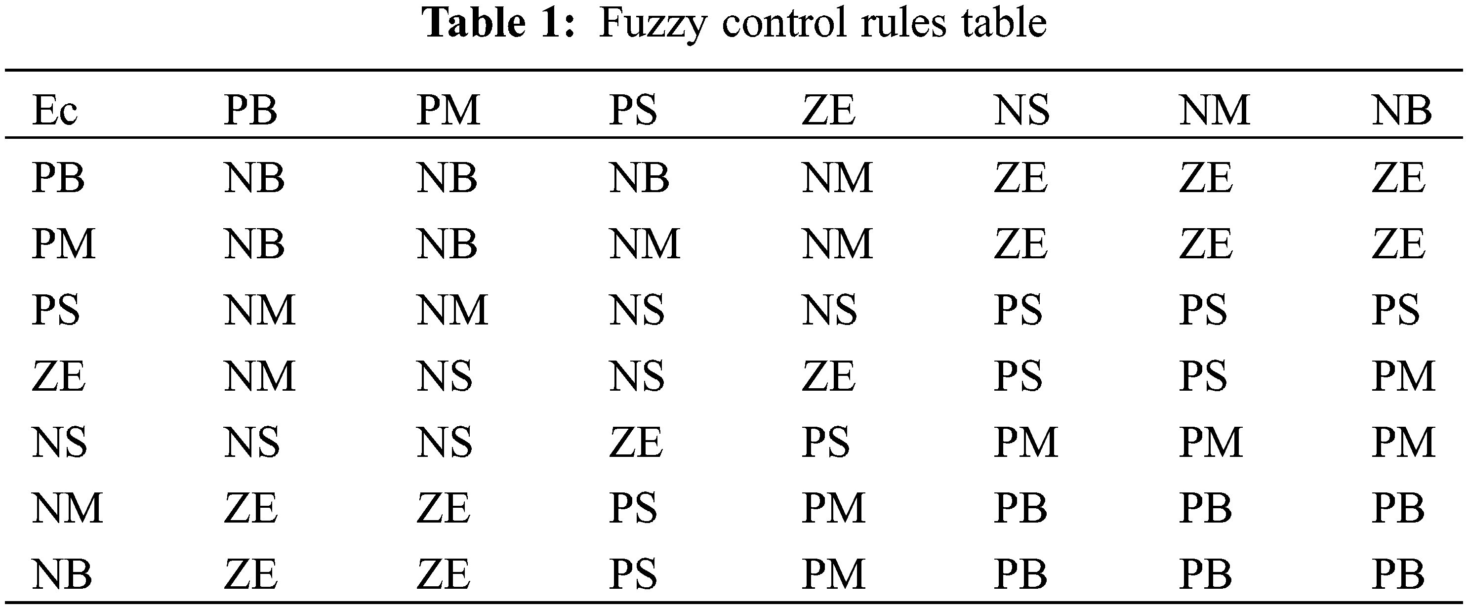
(3) Define fuzzy control rules
For fuzzy input and output variables, the corresponding fuzzy control rules can be determined according to a certain expert experience or fuzzy model, expressed by If... Then conditional sentences. The author also referred to the control method summarized by the actual operator, and finally obtained a series of control rules that comply with the yaw control system composed of fuzzy conditional sentences. In summary, if the error is large, the control quantity must be as short as possible; if the error is relatively small, the error must be minimized. Of course, attention must be paid to ensure the stability of the entire system and minimize unnecessary over-harmonic impact. By summarizing the fuzzy control rules, the fuzzy control rules of the yaw system are obtained as shown in Table 1 [8].
Fuzzy decision of output information
Any fuzzy control rule in the fuzzy control rule table also has its own definite fuzzy relationship, in which R1, R2 ⋅ ⋅ ⋅ R49’s respective algorithms are:
After the “union” operation process of the above 49 fuzzy relations Ri = (i = 1, 2, ⋅ ⋅ ⋅ , 49), the sum fuzzy relation R representing the yaw control system can be obtained, namely:
2.3 Yaw Control Strategy Based on Power Control
The yaw control process based on power control is shown in Fig. 2, where: V is the direction of the wind;
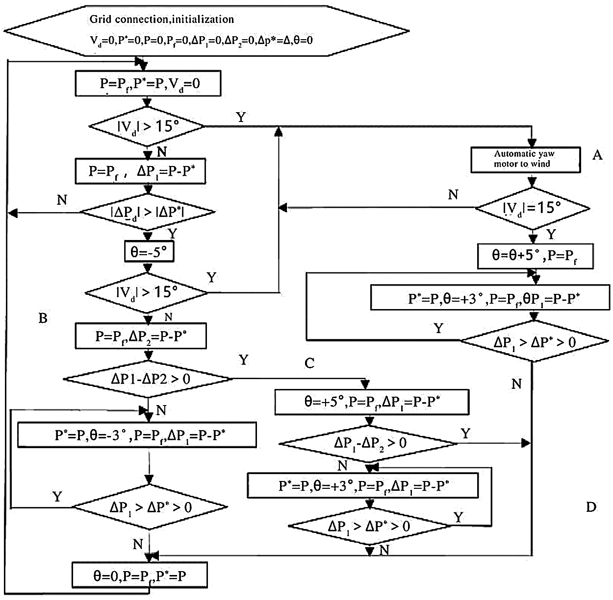
Figure 2: Flow chart of yaw control algorithm
The specific implementation process of yaw control is as follows: When the wind generator is connected to the grid, the yaw control system is initialized and the wind direction is determined. (1) When the wind direction Vd changes the amount >15°, that is, jumps to Part A for fuzzy control based on the wind vane sensor to carry out the wind control, until the change of wind direction Vd is less than 15°, the yaw motor needs to continue to rotate 5° in the original direction and then yaw 3° before power control; Judge the change of ΔP1, if
2.4 Research on Wind Farm Power Optimization Based on Genetic Algorithm
1) Establishment of wind farm multi-objective reactive power optimization model
Within the scope of meeting many constraints, minimize the deviation of wind farm and grid voltage as much as possible, and achieve the lowest possible reactive power compensation capacity, and maximize the quality of the wind farm voltage when the conditions are met, and promote the wind farm reactive power balance is a major goal. Based on the above analysis, this article made the following key considerations when establishing the reactive power optimization model:
① How to minimize the capacity of reactive power compensation;
② To improve the voltage quality;
③ The voltage deviation of wind farm parallel point is reduced to the maximum extent.
In order to minimize the compensation capacity, the following formula is the benchmark:
In Eq. (1), N1 is the compensation points of SVC; Qci is the compensation capacity of node I.
In order to achieve the highest voltage quality, the following formula is used as a reference:
In Eq. (2), N represents the total number of nodes; Ui represents the actual value of the voltage at node I; Uiset represents the voltage rating at node I.
In Eq. (3), Uset represents the rated voltage value that has been clearly defined; The voltage of the junction point expressed by UCQ is the voltage value after reactive power compensation.
Constraints to be met: Power constraints
In Eq. (4), PGi is the value of the active power output of the wind turbine numbered I, and QGi is the value of the reactive power output of the wind turbine numbered I. PLi represents the value of active power at node I within the wind farm, and QLi represents the value of reactive power at node I within the wind farm. Ui is the voltage value at node I; Gij is the phase difference of the conductance between node 1 and node j, Bij is the phase difference of the suscance between node I and node j, θij is the phase difference of the voltage between node I and node j. N2 is the number of nodes located in the wind farm.
The constraint conditions of the control variables are as follows:
In Eq. (5), QCiMIN is the lowest value of reactive power compensation capacity at the compensation point, and QCiMAX is the highest value of reactive power compensation capacity at the compensation point. QCi is the value of the required compensation capacity at the compensation node I; N1 represents the number of compensation points required by SVC; TiMIN is the lowest value of the variation ratio, TiMAX is the maximum value of the variation ratio; Ti is the specific ratio of the transformer; N3 denotes the number of required on-load voltage regulating transformers.
Constraint conditions of state variables that should be met are expressed as follows:
In Eq. (6), QCiMIN is the minimum reactive power accepted by the wind turbine, and QCiMAX is the maximum reactive power accepted by the wind turbine. QGi is the value of reactive power that can be accepted by the unit located at node I; N4 is the total number of generators; UiMIN is the minimum permissible value of the voltage at node I, UiMAX is the maximum permissible value of the voltage at node I; Ui is the voltage value at all nodes within the wind farm; N3 represents the total number of all on-load regulating transformers.
From the six expressions listed above, the required mathematical model of reactive power optimization compensation can be completed. Only by solving the appeal mathematical model can the compensation points and specific compensation capabilities required by SUC be obtained [10].
Because it is a power control algorithm, the detection of the power value is indispensable, and the requirements are relatively high, but it is also relatively valued. This article uses the rotor side measurement, because the input and output power capacity of the rotor side is smaller than the stator side, so the measurement results will be more accurate. The following explains the superiority of the yaw control algorithm based on power control and fuzzy logic control. By setting the following parameters, the engine room and so on the rotational inertia value is small, using A 1.5 MW wind turbine. The selected radius of the wind wheel is r = 35 m, the area of the wind wheel rotation is A = 3848 m2, the efficiency of the gear box is η = 0.97, the transmission ratio is 79.8, air density ρ = 1.225 kg/m3.
The simulation diagram is shown in Figs. 3–5. As can be seen from Fig. 4, the wind direction experienced four stages of change: clockwise 25°, clockwise 10°, counterclockwise 15° and clockwise 10°. At 7, 13, 18 and 22 s, only the wind speed changes. At 15, 20 s, only the wind direction changes. At 10, 25 s, wind direction and wind speed change at the same time to cause power change, but at 10 s, wind direction change is more than 15°, fuzzy control based on the wind sensor is directly realized, and the yaw motor yaw has strong robustness to wind speed changes caused by power changes; at 25 s, the power control algorithm is executed to effectively track the wind direction. The simulation results once again prove the superiority of this algorithm.
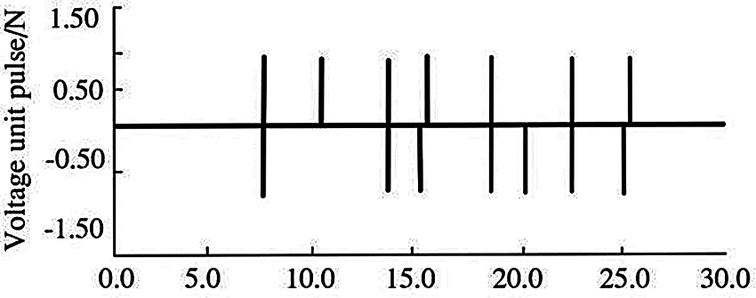
Figure 3: Start and stop state of motor
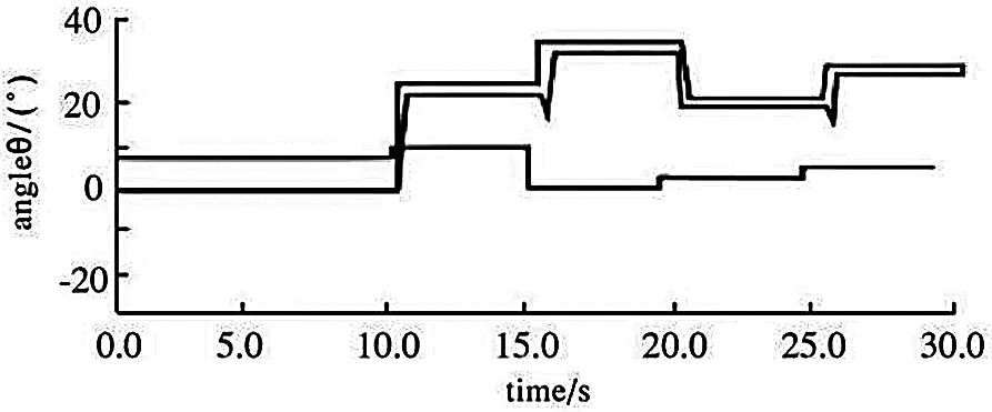
Figure 4: Waveforms of wind direction, yaw Angle and wind speed
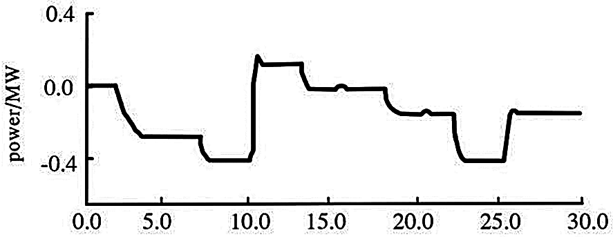
Figure 5: Power curve
Fuzzy control can overcome unfavorable factors such as randomness of wind direction and accurately track changes in wind direction. The power control is simple to implement. It only needs to measure the voltage and current of the generator, and then the rotation of the yaw motor can be controlled by the change of power. The combination of the two can better reflect its superiority. The application of this method has important practical significance and provides a good idea for the operation of wind farms.
Funding Statement: The authors received no specific funding for this study.
Conflicts of Interest: The authors declare that they have no conflicts of interest to report regarding the present study.
1. Wei, X. S., Wang, X. Y., Chen, S. Y. (2020). Research on parameterization and optimization procedure of low-reynolds-number airfoils based on genetic algorithm and bezier curve. Advances in Engineering Software, 149(9), 102864. DOI 10.1016/j.advengsoft.2020.102864. [Google Scholar] [CrossRef]
2. Mayer, M. J., Gróf, G. (2020). Techno-economic optimization of grid-connected, ground-mounted photovoltaic power plants by genetic algorithm based on a comprehensive mathematical model. Solar Energy, 202, 210–226. DOI 10.1016/j.solener.2020.03.109. [Google Scholar] [CrossRef]
3. Liu, M., Zhang, X. K., Wang, D. (2021). Experimental study on the flow characteristics of a plate with a mechanically choked orifice. Fluid Dynamics & Materials Processing, 17(1), 97–107. DOI 10.32604/fdmp.2021.011292. [Google Scholar] [CrossRef]
4. Lakshmanan, V. (2000). Using a genetic algorithm to tune a bounded weak echo region detection algorithm. Journal of Applied Meteorology, 39(2), 222–230. DOI 10.1175/1520-0450(2000)039<0222:UAGATT>2.0.CO;2. [Google Scholar] [CrossRef]
5. Azzawi, A., Shaheed, D. (2020). Evaluation of genetic algorithm optimization in machine learning. Journal of Information Science and Engineering, 36(2), 231–241. DOI 10.6688/JISE.202003_36(2). 0004. [Google Scholar] [CrossRef]
6. Sun, H. Y., Qiu, C. Y., Lu, L., Gao, X. X., Chen, J. et al. (2020). Wind turbine power modelling and optimization using artificial neural network with wind field experimental data. Applied Energy, 280(6), 115880. DOI 10.1016/j.apenergy.2020.115880. [Google Scholar] [CrossRef]
7. El Hraiech, S., Chebbi, A. H., Affi, Z., Romdhane, L. (2020). Genetic algorithm coupled with the Krawczyk method for multi-objective design parameters optimization of the 3-UPU manipulator. Robotica, 38(6), 1138–1154. DOI 10.1017/S0263574719001292. [Google Scholar] [CrossRef]
8. Petrov, T. I. (2021). Modification of the genetic algorithm for comprehensive topological optimization of the synchronous motors rotor. Power Engineering Research Equipment Technology, 23(3), 70–79. DOI 10.30724/1998-9903-2021-23-3-70-79. [Google Scholar] [CrossRef]
9. Wang, Q. H., Yang, J. Z., Luo, W. (2021). Flow simulation of a horizontal well with two types of completions in the frame of a wellbore–annulus–reservoir model. Fluid Dynamics & Materials Processing, 17(1), 215–233. DOI 10.32604/fdmp.2021.011914. [Google Scholar] [CrossRef]
10. Jiang, W. P., Jiang, Z. C., Wang, L. Y., Min, J., Zhu, Y. et al. (2021). Application of characteristic model-based principal component analysis in optimization of flowmeter parameters. Mathematical Problems in Engineering, 2021(1), 1–9. DOI 10.1155/2021/9978791. [Google Scholar] [CrossRef]
 | This work is licensed under a Creative Commons Attribution 4.0 International License, which permits unrestricted use, distribution, and reproduction in any medium, provided the original work is properly cited. |