| Fluid Dynamics & Materials Processing |
DOI: 10.32604/fdmp.2022.018423
ARTICLE
Experimental Study on the Performance of an Onboard Hollow-Fiber-Membrane Air Separation Module
1School of Mechanical Engineering, Hunan University of Arts and Science, Changde, 415000, China
2School of Aeronautic Science and Engineering, Beihang University, Beijing, 100191, China
*Corresponding Author: Yu Zeng. Email: zengyu@buaa.edu.cn
Received: 23 July 2021; Accepted: 03 October 2021
Abstract: Onboard air separation devices, based on hollow fiber membranes, are traditionally used for the optimization of aircraft fuel tank inerting systems. In the present study, a set of tests have been designed and executed to assess the air separation performances of these systems for different air inlet temperatures (70°C∼110°C), inlet pressures (0.1∼0.4 MPa), volume flow rates of nitrogen-enriched air (NEA) (30∼120 L/min) and flight altitudes (1.5∼18 km). In particular, the temperature, pressure, volume flow rate, and oxygen concentration of air, NEA and oxygen-enriched air (OEA) have been measured. The experimental results show that the oxygen concentration of NEA, air separation coefficient, and nitrogen utilization coefficient decrease with the rising of air inlet temperature, air inlet pressure, and flight altitude. The effect of air inlet pressure on the above three parameters is significant, while the influence of air inlet temperature and flight altitude is relatively small.
Keywords: Aircraft fuel tank inerting; hollow-fiber-membrane; air separation; experimental study; onboard air separation device
Fire or explosion of aircraft fuel systems is one of the main causes of aircraft crashes [1,2]. During the flight once the fuel vapor is mixed with oxygen-enriched air (OEA) in the aircraft fuel tank encounters ignition sources such as electric sparks or external fire attack, it will cause combustion and even lead to explosion [3]. The aircraft fuel tank inerting system uses air separation technology to produce nitrogen-enriched air (NEA), and uses the generated NEA to wash or flush the upper space of the fuel tank, to ensure that the oxygen concentration in the upper space of the aircraft fuel tank is within the safety limit. According to different air separation methods, the nitrogen production technology can be divided into molecular sieve nitrogen production technology and membrane separation nitrogen production technology [4]. Molecular sieve nitrogen production technology uses adsorbents in molecular sieves to adsorb nitrogen and oxygen in the air at different adsorption rates, and separates oxygen and nitrogen by changing the adsorption and analytical pressure through circulation [5]. Membrane separation technology takes advantage of the different permeability of nitrogen and oxygen in the hollow-fiber-membrane and the selective permeability of airborne nitrogen and oxygen to separate oxygen and nitrogen in the air. The membrane separation method is based on the fact that the permeability of membrane materials to different molecular gases is different, and the gas with high permeability is more ready to pass through the membrane wall, and the original gas mixture can be divided into two streams when passing the membrane device. Hollow fiber membrane is widely used in the field of gas separation. Hosseini et al. [6] studied the application of a hollow-fiber-membrance permeator for the separation of O2/N2 mixtures. Choi et al. [7] used a polymer hollow-fiber-membrane to separate sulfur hexafluoride from a nitrogen/sulfur hexafluoride mixture. Roslan et al. [8] investigated the application of a hollow-fiber-membrance in the separation of CO2/CH4 and O2/N2. Raza et al. [9] developed multiple-layer composite CTA/CDA hollow fiber membranes for the separation of CO2/CH4. As shown in Fig. 1, when the air passes through the hollow-fiber-membrane device, it can be divided into two streams, one is nitrogen-enriched air and the other is oxygen-enriched air [10]. Under certain requirements of separation performance, the amount of gas required by the membrane separation system is half of that of the molecular sieve, and the weight and volume of the equipment are smaller than that of the molecular sieve. There are no moving parts in the system, and the life is long and the reliability is high. Therefore, the membrane separation method is mainly used in the onboard nitrogen production system at present [11].
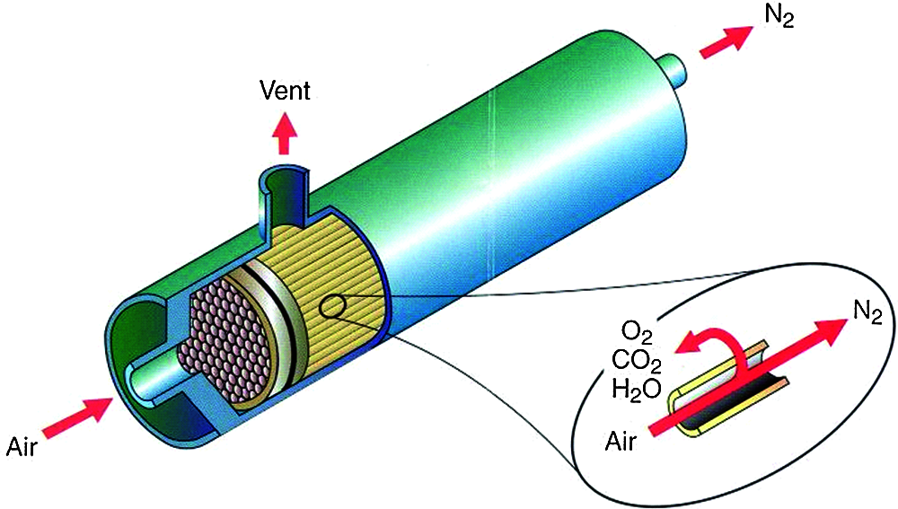
Figure 1: Schematic of a hollow-fiber-membrane module
As an important numerical simulation means of the fluid behavior [12,13], CFD is gradually applied to the study of air separation characteristics of hollow-fiber-membrane. The hollow-fiber-membrane technology and extraction process were reviewed in [14,15]. Iwai et al. [16] developed a simulation model of the hollow membrane gas separation system and analyzed the separation performance of the system for the air–H2–H2O mixture. Sugiyama et al. [17] established the transient response simulation model of the fiber membrane and used it to analyze the separation effect of tritium gas from the space atmosphere of the fiber membrane module. Ahmad et al. [18] established the mathematical model of hollow fiber membrane, and studied the effects of temperature and pressure on the permeance of the hollow fiber membrane based on the mathematical model. Cai et al. [19] investigated the module design method and its impact of the design fact on the performance of cross-flow hollow fiber membrane contactors with 3D numerical analysis method. Ma et al. [20] used CFD method to simulate the impact of fiber distance and position on the interaction between fibers within a hollow fiber membrane bundle. Lau et al. [21] developed a hollow fiber membrane simulation model, which can be embedded into the commercial software Aspen HYSYS for component level analysis, and this model was also verified by experiments. Ardaneh et al. [22] studied a two-dimensional mathematical analysis model of hollow fiber membrane, and analyzed the hydrogen recovery performance of the industrial hollow fiber membrane module based on the model. Zeng et al. [23] simulated the flow performance of the hollow fiber membrane air separation module based on the software Flowmaster and compared the simulation results with the experimental data. Li et al. [24] investigated the performance of the onboard inert gas generation system with a turbocharger using AMESim software. However, there are few experimental studies on the performance of the onboard hollow fiber membrane module. Cavage [1] developed three different measurement methods of oxygen concentration in the gas phase space of different fuel tanks. Liu et al. [25] conducted an experimental study on the separating performance of the hollow fiber membrane module, and their results showed that the increase of working temperature can significantly increase the production of oxygen-enriched air. Cai et al. [26] conducted numerical and experimental studies on the hollow-fiber-membrane onboard inert gas generation system, and the effect of inlet air parameters on NEA generation capacity was analyzed.
The onboard hollow-fiber-membrane air separation devices have been widely used in aircraft fuel tank inerting systems, and the air separation performance of hollow-fiber-membrane module is the basis for the design and optimization of airborne fuel tank inerting system and products. The main factors affecting the permeability of the hollow-fiber-membrane module are the temperature and partial pressure of gas on both sides of membrane. Therefore, the performance of the onboard hollow-fiber-membrane air separation module will be affected by the inlet pressure and temperature of the air, the exhaust pressure of the OEA, and the flow rate of the NEA. To investigate the air separation performance of onboard air separation devices under different working conditions, this paper designed and built a set of onboard hollow fiber membrane air separation device performance test system. Parameters such as the air inlet pressure (Pin), air inlet temperature (Tin), volume flow rate of NEA (QNEA), and ambient pressure in the air separation device could be adjusted through the test platform. This experimental system was used to test the performance of the air separation device and analyze the influences of Pin, Tin, QNEA and flight altitude on the oxygen concentration of NEA, air separation coefficient, and nitrogen utilization of the air separation device. The experimental results can be used as a reference for the optimization design of membrane module parameters and inerting strategy of aircraft inerting systems.
2 Design of Experimental System
2.1 Schematic of the Testing System
The schematic of the testing system is shown as Fig. 2. The screw compressor, filter and adsorption drying unit are used to provide high-pressure dried air. The inlet pressure of the test unit of the onboard air separation device is adjusted by an electronic pressure reducer. The inlet temperature is adjusted by an air heater with a silicon Controlled Rectifier Regulator. The high-altitude environment simulation unit is composed of a high-altitude environment cabin, vacuum pump units, and vacuum regulating valves, which is used to simulate the low-pressure environment at different flight altitudes. The performance test unit of the onboard air separation module is composed of flow control valves, flow meters, and oxygen meters, which can automatically adjust the flow rate of NEA and measure its flow rate, temperature, pressure, oxygen concentration and other parameters.
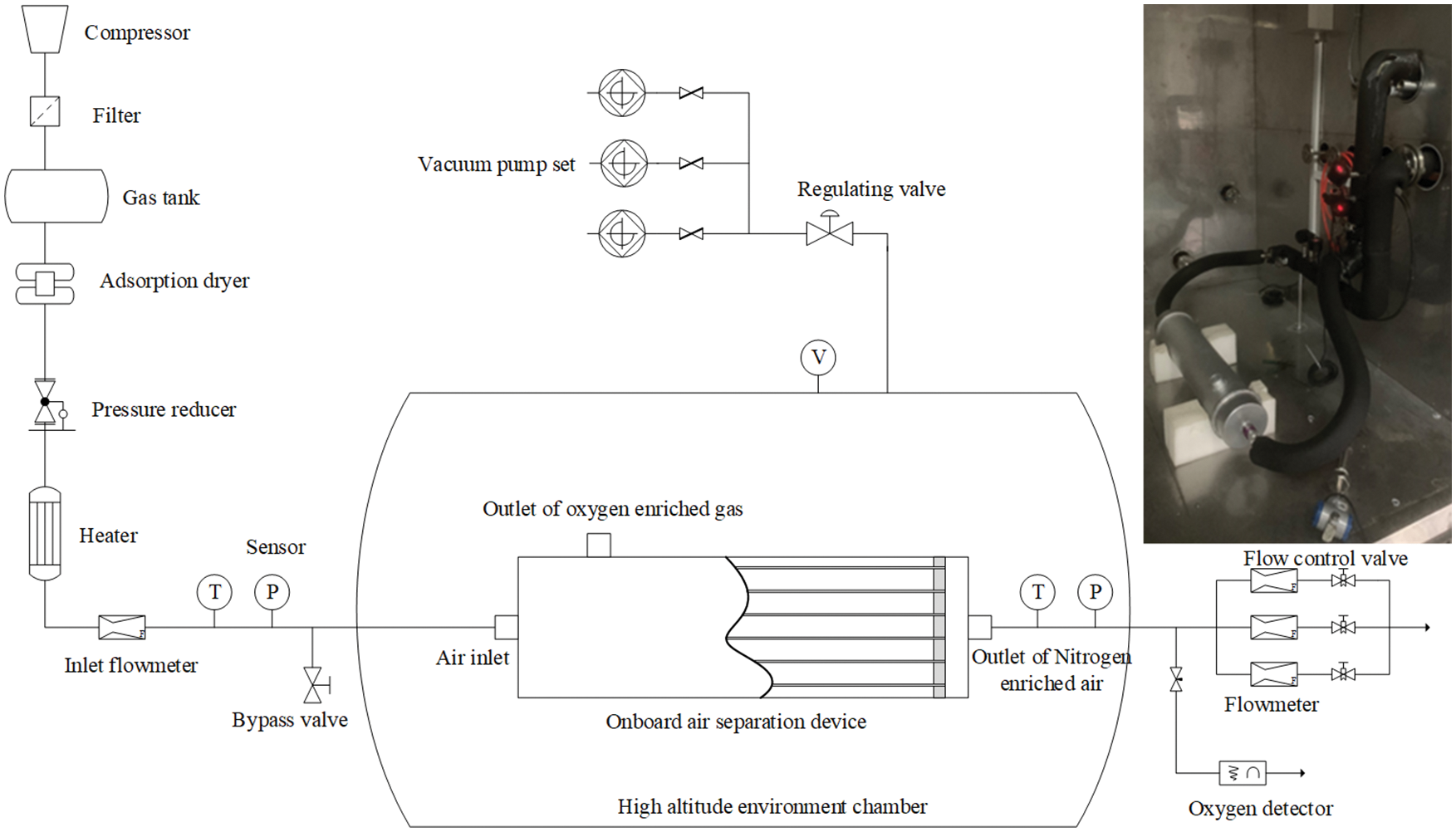
Figure 2: Schematic of air separation module testing system
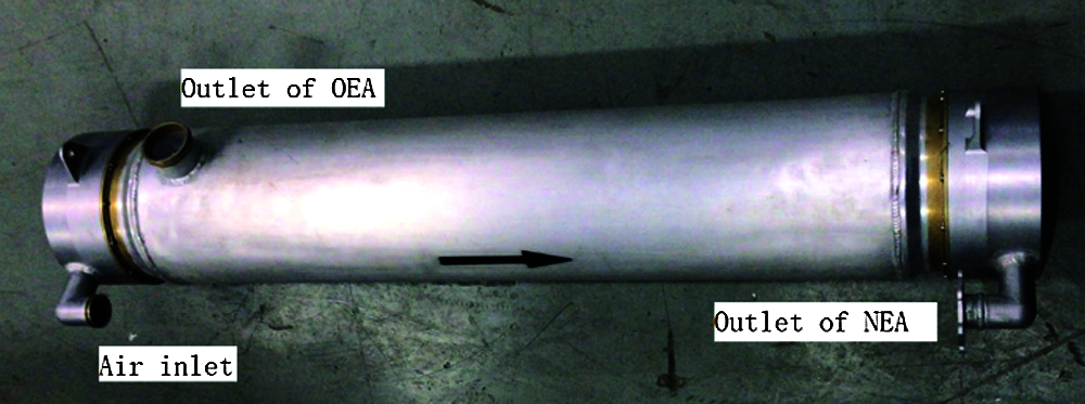
Figure 3: The onboard hollow-fiber-membrane air separation module
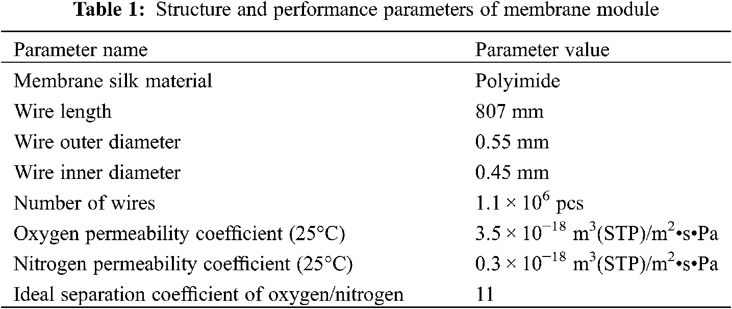
The test sample used in this experiment is the principle prototype of the onboard air separation module as shown in Fig. 3. The air separation device uses a long cylindrical aluminum alloy shell equipped with a membrane bundle body composed of a plurality of hollow fiber membranes. The two ends of the membrane bundle body are sealed by casting resin processing. Both sealed ends are connected to the shell tightly by flanges and o-washers. The two ends of the device are, respectively, the air inlet and the NEA outlet. The flow form of the gas is countercurrent. The oxygen-enriched air (OEA) outlet is placed on the side of the air inlet. The structure parameters of the sample membrane components of the onboard air separation device are as shown in Table 1.
The variables involved in this experimental research mainly include inlet temperature, inlet pressure, volume flow rate of NEA, and ambient pressure (simulate the flight altitude). To investigate the air separation performance of the onboard air separation module in different air inlet pressure and temperature, environmental pressure, and flow rate demand of the NEA during the actual flight, the working conditions are set as shown as in Table 2.
Air separation coefficient α is defined as Eq. (1), which represents the separation capability of the air separation device [25].
where
Air separation coefficient α mainly describes the permeability efficiency of hollow-fiber-membrane in the separation process of air separation devices, which can be used as a reference for the preparation and material selection of hollow-membrane-fiber. However, it cannot directly reflect the inert performance of the module itself to the airborne fuel system. Thus, the nitrogen utilization efficiency θ is defined as Eq. (2).
θ can directly reflect the corresponding relationship between the volume flow of NEA and inlet air for the air separation device. It represents the amount of engine bleed gas consumed to generate a certain amount of NEA.
3 Experimental Results and Analysis
The performance test for the onboard air separation device was carried out with the parameters listed in Table 1 using the test system as Fig. 2 shows. The experimental conditions are listed in Table 2. The effect of flight altitude on the performance of the onboard air separation device was investigated under constant inlet temperature and pressure (Tin = 100°C, Pin = 0.4 MPa). The experimental results and analysis are as follow.
3.1 The Effect of Tin on the Air Separation Performance
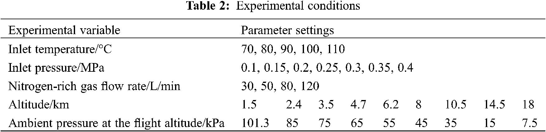
As can be seen from Fig. 4, the oxygen concentration of NEA (
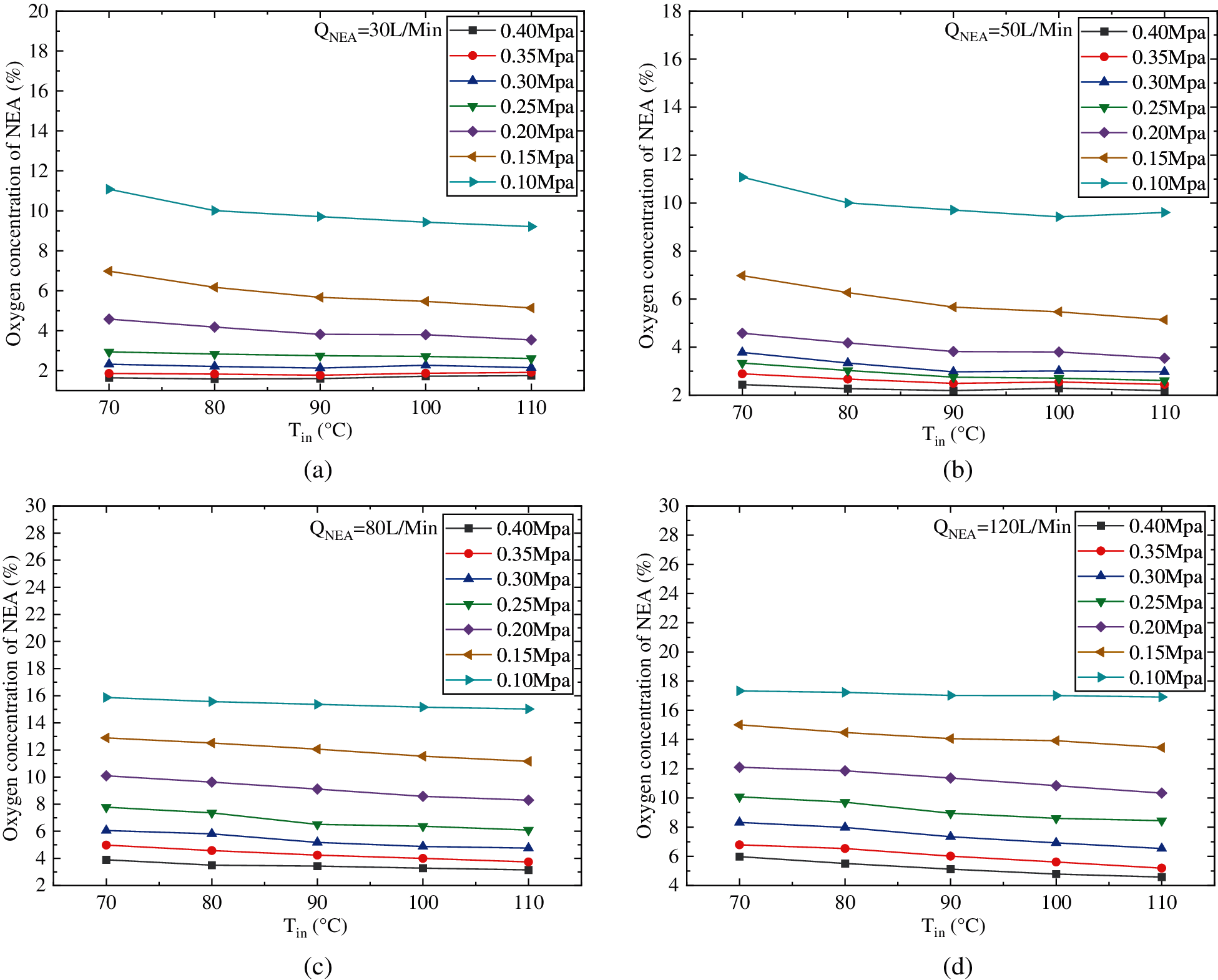
Figure 4: Effect of air inlet temperature on oxygen concentration of NEA (a) QNEA = 30 L/min (b) QNEA = 50 L/min (c) QNEA = 80 L/min (d) QNEA = 120 L/min
Fig. 5 shows the effect of air inlet temperature on air separation coefficient (α). As the experimental results are shown, α decreases with the rising of Tin and this downtrend gradually becomes flat. As the definition of Eq. (1),
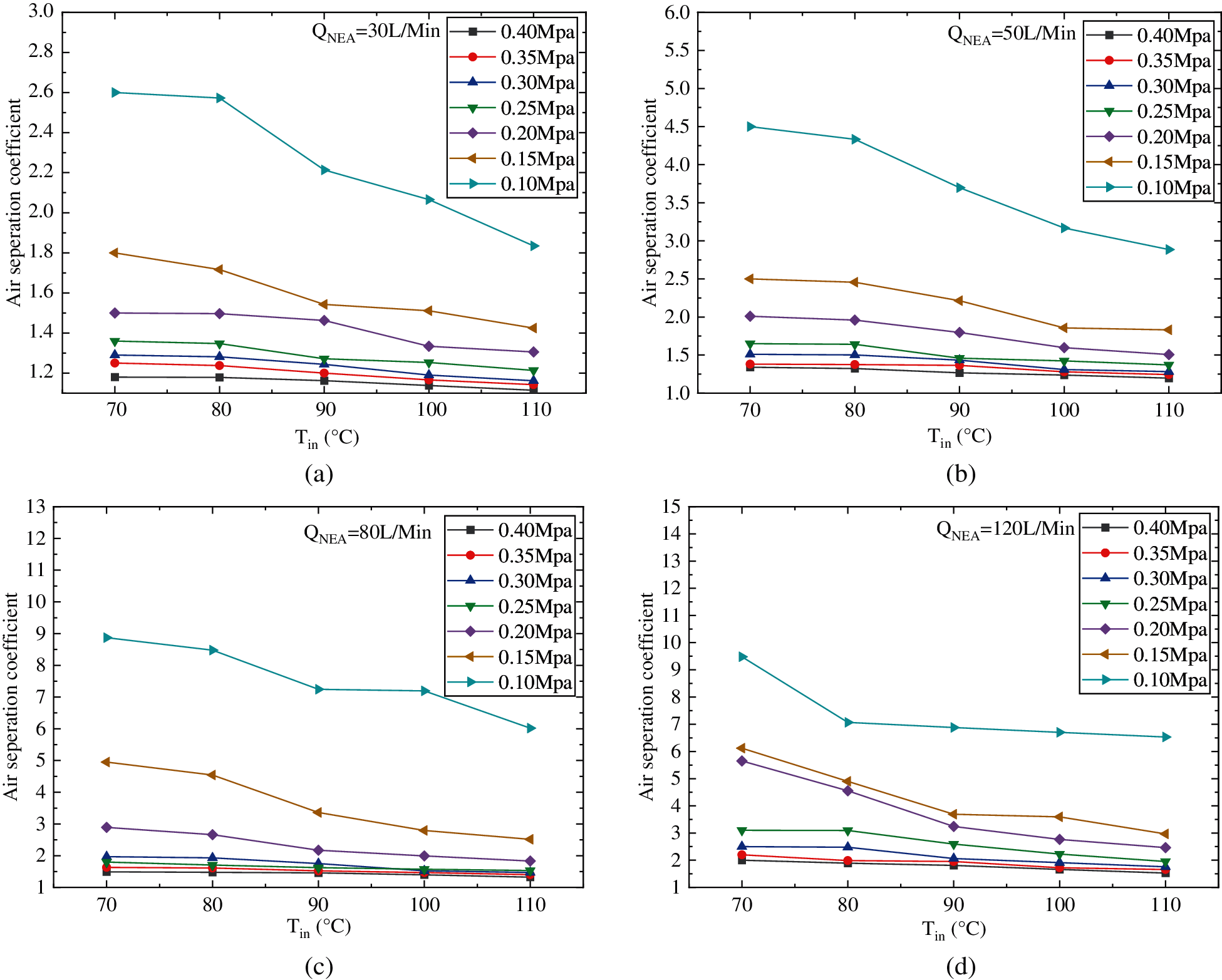
Figure 5: Effect of air inlet temperature on air separation coefficient (a) QNEA = 30 L/min (b) QNEA = 50 L/min (c) QNEA = 80 L/min (d) QNEA = 120 L/min
Figure 6: Effect of air inlet temperature on nitrogen utilization coefficient (a) QNEA = 30 L/min (b) QNEA = 50 L/min (c) QNEA = 80 L/min (d) QNEA = 120 L/min
Fig. 6 shows the effect of air inlet temperature on the nitrogen utilization coefficient (θ). Based on the experimental results, we can see that θ decreases with the increase of Tin. This is because the permeability of the hollow fiber membrane for oxygen and nitrogen both increases with the increase of Tin, as a result the amount of nitrogen and oxygen penetration will both increase, and more inlet air is needed to maintain QNEA, which results in the downward trend of θ with the rising of Tin.
3.2 The Effect of Pin on the Air Separation Performance
The influence of inlet pressure on oxygen concentration of NEA (
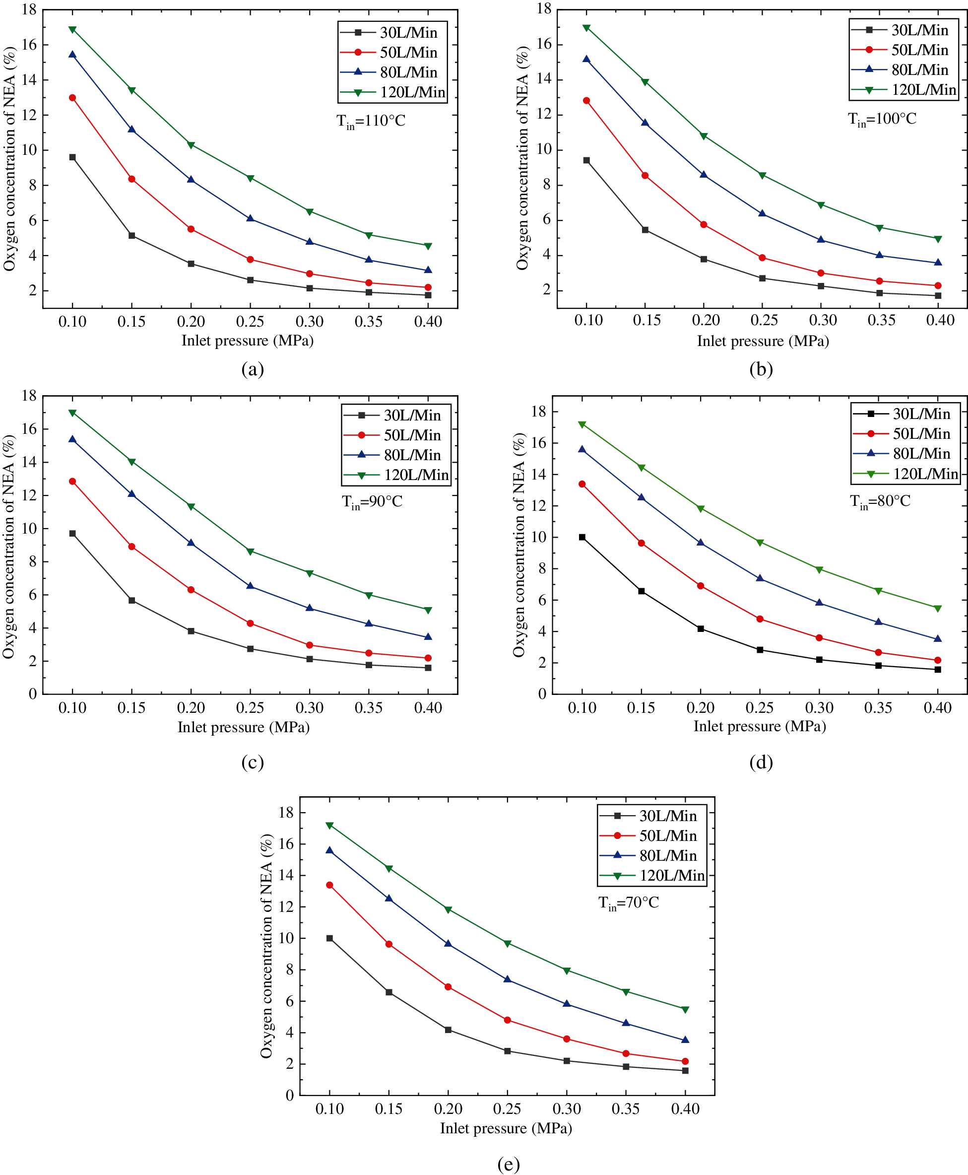
Figure 7: Effect of air inlet pressure on oxygen concentration of NEA (a) Tin = 110°C (b) Tin = 100°C (c) Tin = 90°C (d) Tin = 80°C (e) Tin = 70°C
As can be seen from Fig. 7, under the condition of constant Tin and QNEA, the oxygen concentration of NEA decreases gradually with the rising of Pin, and the decreasing trend of oxygen concentration of NEA slows down with the increase of Pin. Because with the increase of air inlet pressure, the pressure difference between the two sides of the fiber membrane rises up, which leads to increase the driving force of gas penetration. As the permeability coefficient of oxygen is greater than that of nitrogen, the permeability of oxygen increases more than that of nitrogen. As a result, the oxygen concentration of the NEA decreases. However, with the continuous increase of Pin, more oxygen permeates through the fiber membrane, and the increasing trend of partial pressure difference of oxygen between the two sides of the fiber membrane slows down, and the decreasing trend of the oxygen concentration of NEA will also slow down. Further analysis shows that as the Pingoes up to the max value (0.4 MPa in this experiment study) under the conditions of the lowest QNEA (30 L/min in this experiment study), the air separate ability of the hollow-fiber-membrane reaches its limit, that is, the lowest oxygen concentration of NEA derived by the hollow-fiber-membrane separation device used in this experiment is about 2%.
Fig. 8 shows the effect of Pin on air separation coefficient α. As the test results are shown, with the increase of Pin, α decreases and the downtrend slows down. This is because the pressure difference between the two sides of the hollow-fiber-membrane increases with the rising of Pin, and the gas permeability driving force also goes up. The permeability amount of oxygen and nitrogen will both increase. Although the permeability coefficient of oxygen is greater than that of nitrogen, the proportion of nitrogen in the air is much higher, more nitrogen is removed through the membrane and exits with OEA, which results in
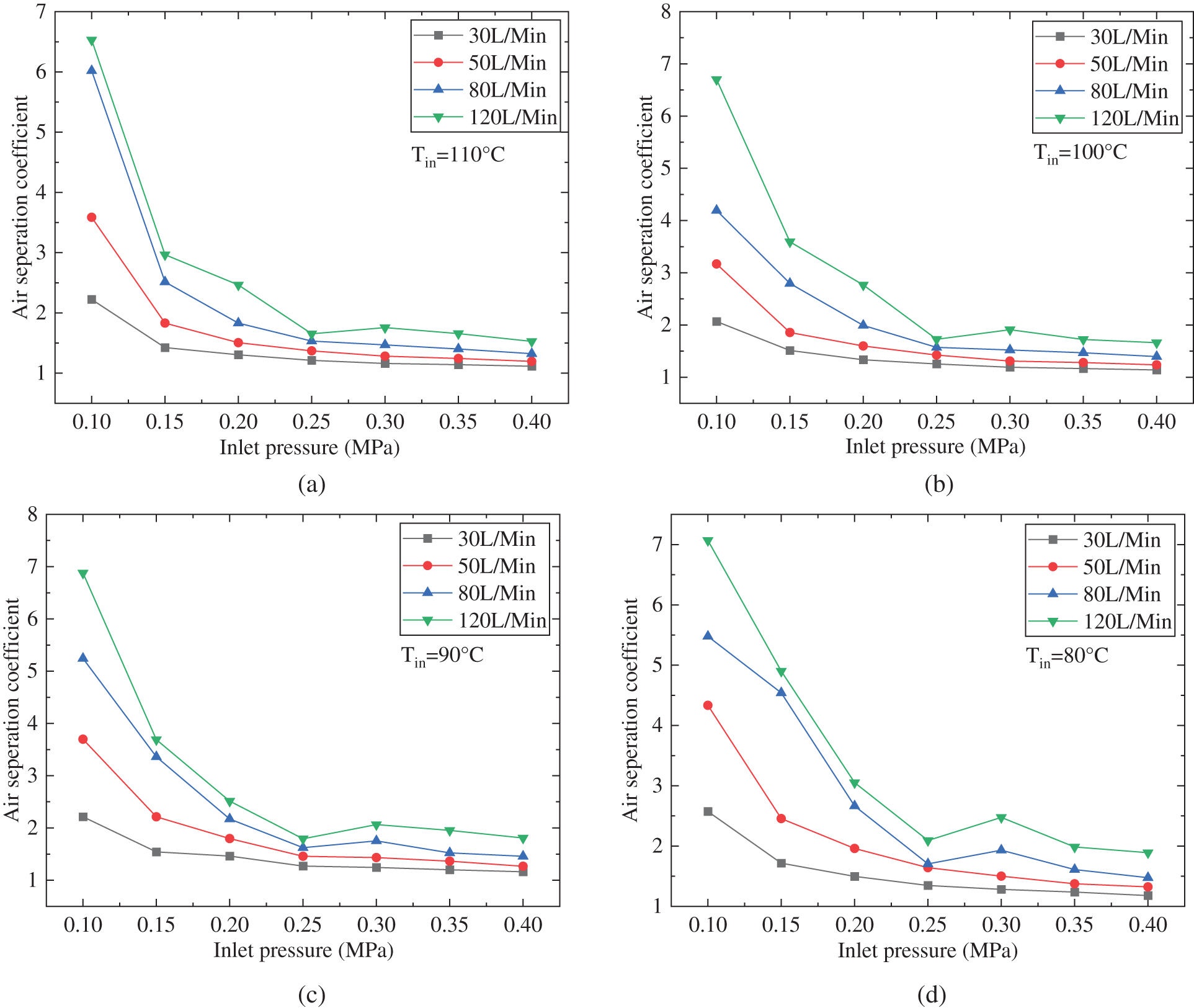
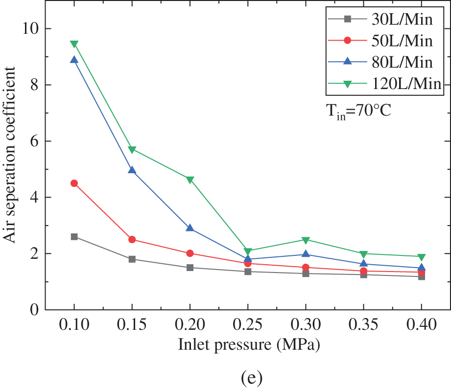
Figure 8: Effect of inlet pressure on the air separation coefficient (a) Tin = 110°C (b) Tin = 100°C (c) Tin = 90°C (d) Tin = 80°C (e) Tin = 70°C
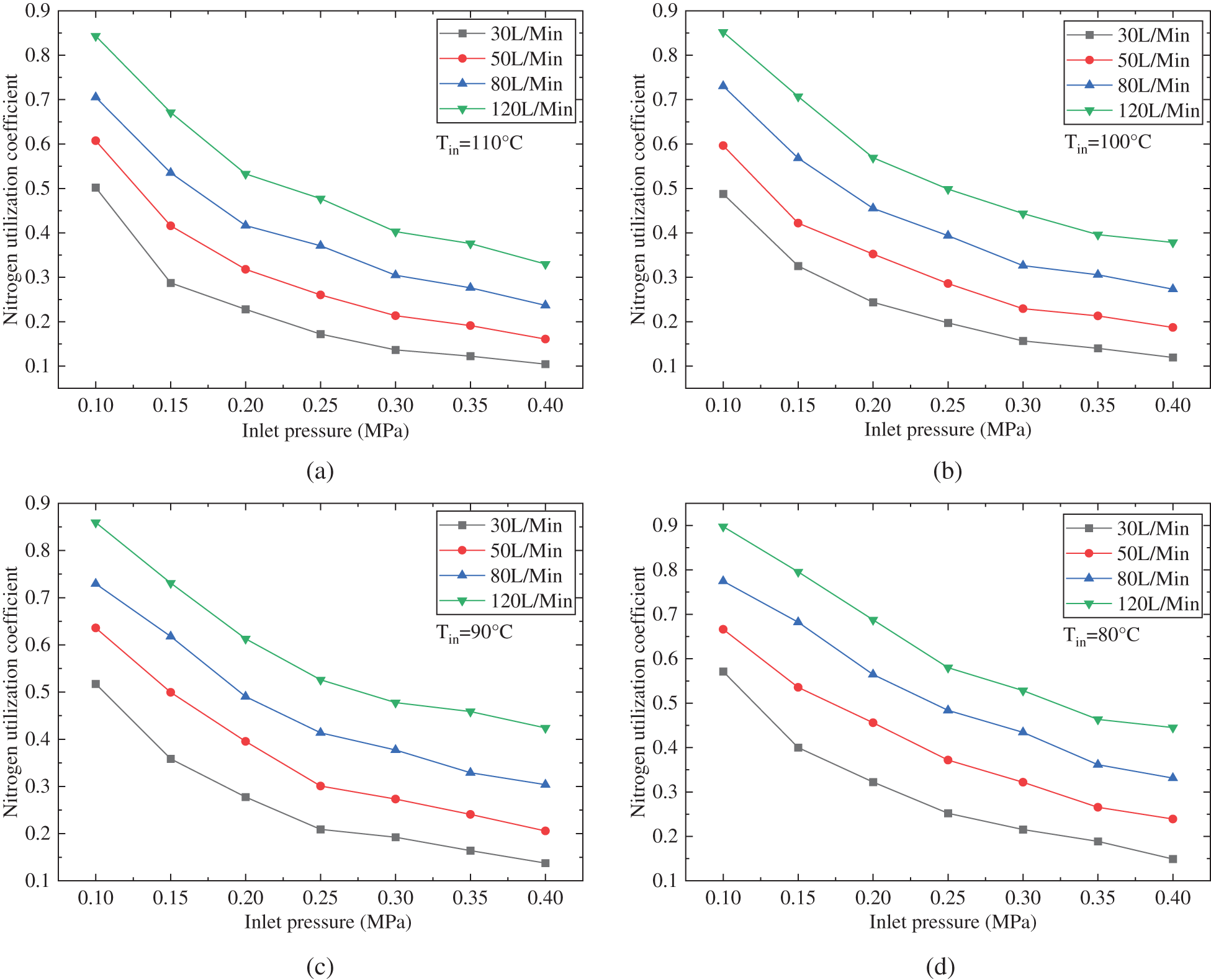
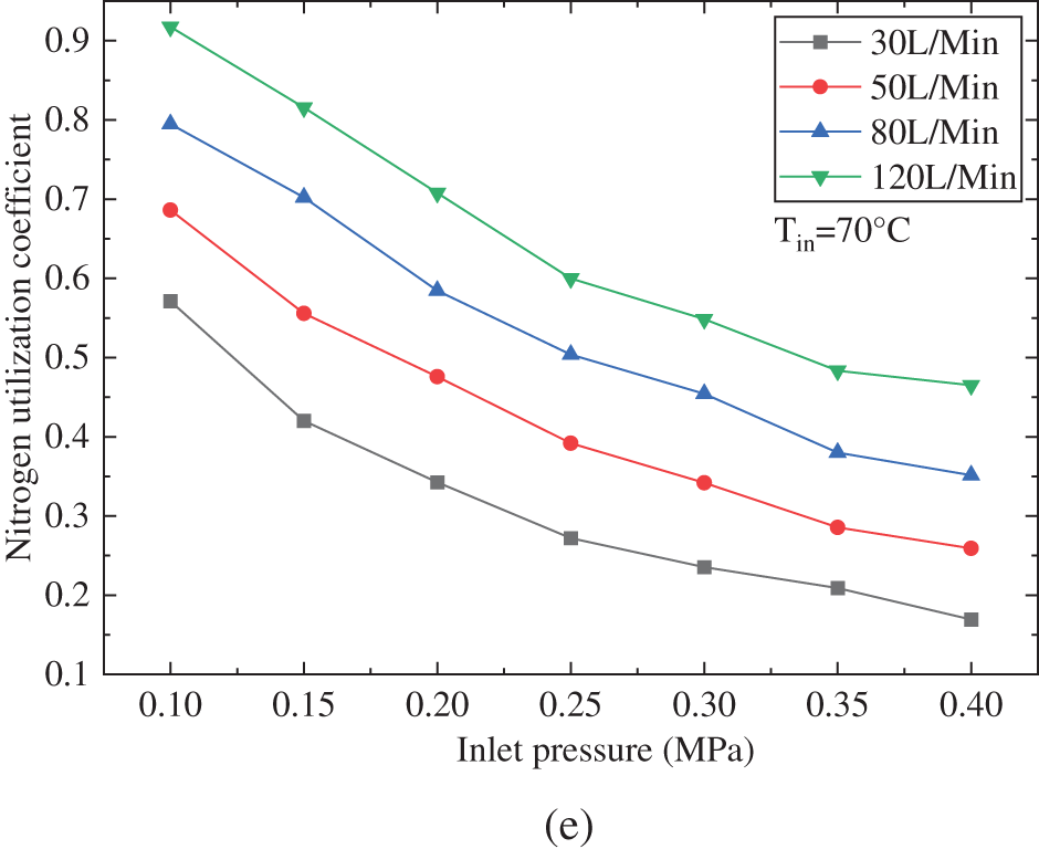
Figure 9: Effect of inlet pressure on nitrogen utilization coefficient (a) Tin = 110°C (b) Tin = 100°C (c) Tin = 90°C (d) Tin = 80°C (e) Tin = 70°C
According to Fig. 9, the influence of inlet pressure on the nitrogen utilization coefficient θ was analyzed, and it was found that within a certain range of Pin and QNEA, θ showed a decreasing trend with the increase of Pin, and the decreasing trend of θ also slowed down with the increase of Pin. This is because when the Pin increases, the pressure difference between the two sides of the hollow fiber membrane increases, so does the gas permeability driving force, the permeability rate of oxygen and nitrogen, and then the permeability amount of oxygen and nitrogen will both increase. To keep the QNEA unchanged, the air inlet flow rate needs to be increased, and then θ will decrease. With the further increase of the Pin, the increasing trend of the permeability driving force slows down, and the downward trend of θ will also slow down.
3.3 The Effect of Flight Altitude on the Air Separation Performance
To study the influence of flight altitude on the nitrogen production performance of the onboard hollow-fiber-membrane air separation module, the air inlet pressure and temperature were kept constant (Tin = 100°C, Pin = 0.4 MPa). QNEA is set to 30, 50, 80, and 120 L/Min. The effects of flight altitude on the
As shown in Fig. 10, the oxygen concentration of NEA (
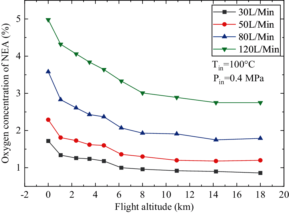
Figure 10: Effect of flight altitude on oxygen concentration of NEA
Fig. 11 shows the effect of flight altitude on air separation coefficient α. With the increase of flight altitude, α shows a dropping trend and this tendency gradually becomes flat. This is also because the exhaust pressure decreases as the rising of the flight altitude, the pressure difference between the two sides of the hollow fiber membrane increases, and the gas permeability driving force also goes up. The permeability amount of oxygen and nitrogen will both increase. Although the permeability coefficient of oxygen is greater than that of nitrogen, the proportion of nitrogen in the air is much higher, more nitrogen is removed through the membrane and exits with OEA, which results in
Fig. 12 shows the effect of flight altitude on nitrogen utilization efficiency θ. This value decreases with the increase of flight altitude at different QNEA. As the flight altitude increases, the partial pressure of nitrogen and oxygen at the exhaust side decreases, the pressure difference between the two sides of the hollow-fiber-membrane increases, and the amount of permeable nitrogen and oxygen increases. As a result, more bleed air is needed to make the QNEA remain constant with the flight altitude rising, and this effect will also gradually weaken with the increase of flight altitude.
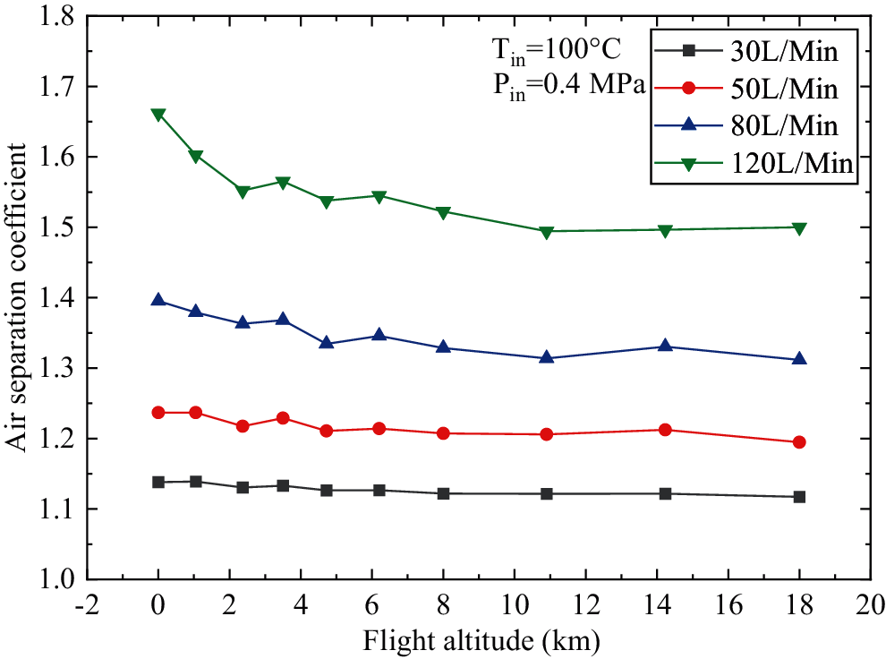
Figure 11: Effect of flight altitude on air separation coefficient
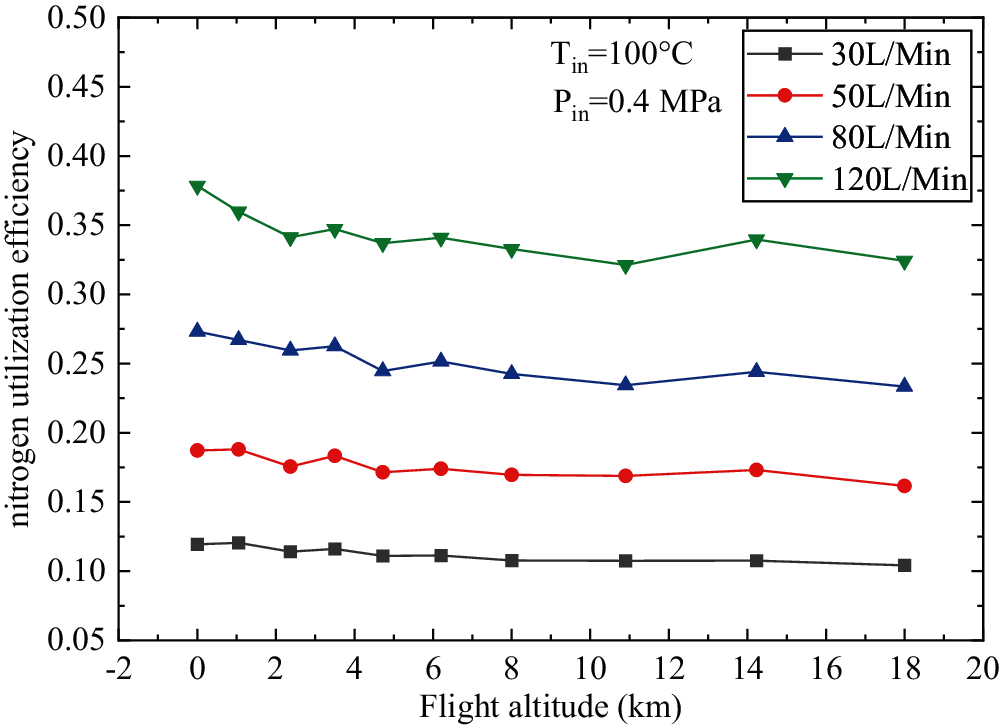
Figure 12: Effect of flight altitude on nitrogen utilization efficiency
Experimental system was designed and built for the separation performance testing of a hollow-fiber-membrane air separation module. Test was conducted under different air inlet temperature, air inlet pressure, flow rate of NEA, and flight altitude referring to the actual flight process. The effects of these four parameters on the oxygen concentration of NEA, air separation coefficient, and nitrogen utilization efficiency were analyzed.
(1) The oxygen concentration of NEA, air separation coefficient, and nitrogen utilization efficiency decrease with the rise of air inlet temperature under constant air inlet pressure and volume flow rate of NEA, and the effect of air inlet temperature on the oxygen concentration of NEA and nitrogen utilization efficiency is not significant.
(2) The oxygen concentration of NEA, air separation coefficient, and nitrogen utilization efficiency significantly decrease with the rising of air inlet pressure under constant air inlet temperature and volume flow rate of NEA, and the downward trend will gradually slow down.
(3) The oxygen concentration of NEA, air separation coefficient, and nitrogen utilization efficiency decrease with the increase of flight altitude under constant air inlet pressure, air inlet temperature, and volume flow rate of NEA. As the flight altitude continues to increase, the impact becomes less significant.
Acknowledgement: The authors are grateful to Department of Science and Technology and Department of Education of Hunan Province for granting this project.
Funding Statement: This project is supported by the Fund of Natural Science Project of Hunan Province, China, with the Item No. 2020JJ5393. Education Department of Hunan Province, China, with the Item No. 18C0735.
Conflicts of Interest: The authors declare that they have no conflicts of interest to report regarding the present study.
1. Cavage, W. M. (2009). Measuring oxygen concentration in a fuel tank ullage. In: U.S. air force T and E days 2009, Albuquerque, New Mexico. [Google Scholar]
2. Pei, Y., Shi, B. (2016). Method for analyzing the effect of projectile impact on aircraft fuel tank inerting for survivability design. Proceedings of the Institution of Mechanical Engineers, Part G: Journal of Aerospace Engineering, 230(13), 2345–2355. DOI 10.1177/0954410015623573. [Google Scholar] [CrossRef]
3. Liu, C., Du, Y., Liang, J., Meng, H., Wang, J. et al. (2020). Large eddy simulation of gasoline-air mixture explosion in long duct with branch structure. Fluid Dynamics & Materials Processing, 16(3), 537–547. DOI 10.32604/fdmp.2020.09119. [Google Scholar] [CrossRef]
4. Feng, S. Y., Liu, G. N., Jiang, R. J., Chen, G. H. (2021). Research status and development trend of aircraft fuel tank on-board inerting technology. Journal of Aerospace Power, 36(3), 616–625. DOI 10.13224/j.cnki.jasp.2021.03.017. [Google Scholar] [CrossRef]
5. Zeng, Y., Yang, X., Pan, R., Sun, B., Wan, D. (2019). Experimental study on oxygen production performance of multi-bed molecular sieves. IEEE 10th International Conference on Mechanical and Aerospace Engineering, pp. 482–485. Brussels, Belgium. [Google Scholar]
6. Hosseini, S. S., Najari, S., Kundu, P. K., Tan, N. R., Roodashti, S. M. (2015). Simulation and sensitivity analysis of transport in asymmetric hollow fiber membrane permeators for air separation. RSC Advances, 5(105), 86359–86370. DOI 10.1039/C5RA13943K. [Google Scholar] [CrossRef]
7. Choi, J. W., Lee, S., An, B., Kim, S. B., Lee, S. H. (2014). Separation of sulfur hexafluoride from a nitrogen/sulfur hexafluoride mixture using a polymer hollow fiber membrane. Water, Air, and Soil Pollution, 225(2), 1807. DOI 10.1007/s11270-013-1807-7. [Google Scholar] [CrossRef]
8. Roslan, R. A., Lau, W. J., Sakthivel, D. B., Khademi, S., Zulhairun, A. K. et al. (2018). Separation of CO2/CH4 and O2/N2 by polysulfone hollow fiber membranes: Effects of membrane support properties and surface coating materials. Journal of Polymer Engineering, 38(9), 871–880. DOI 10.1515/polyeng-2017-0272. [Google Scholar] [CrossRef]
9. Raza, A., Askari, M., Liang, C. Z., Peng, N., Farrukh, S. et al. (2021). Advanced multiple-layer composite CTA/CDA hollow fiber membranes for CO2 separations. Journal of Membrane Science, 625, 119124. DOI 10.1016/j.memsci.2021.119124. [Google Scholar] [CrossRef]
10. Burns, M., Cavage, W. M. (2001). Inerting of a vented aircraft fuel tank test article with nitrogen-enriched air. Fuel tanks. [Google Scholar]
11. Reynolds, T. L., Eklund, T. I., Haack, G. A. (2001). Onboard Inert Gas Generation System/Onboard Oxygen Gas Generation System (OBIGGS/OBOGS) Study. Part 1: Aircraft System Requirements. Boeing Commercial Airplanes Group, Seattle, Washington. [Google Scholar]
12. Wang, Y., Wang, D., Xue, Y., Shi, D., Zhang, X. et al. (2021). Numerical and experimental study of a tornado mixer. Fluid Dynamics and Materials Processing, 17(6), 1113–1127. DOI 10.32604/fdmp.2021.017591. [Google Scholar] [CrossRef]
13. Song, J., Kharoua, N., Khezzar, L., Alshehhi, M. (2021). Numerical simulation of turbulent swirling pipe flow with an internal conical bluff body. Fluid Dynamics & Materials Processing, 17(2), 455–470. DOI 10.32604/fdmp.2021.014370. [Google Scholar] [CrossRef]
14. Sirkar, K. K. (2008). Membranes, phase interfaces, and separations: Novel techniques and membranes–An overview. Industrial and Engineering Chemistry Research, 47(15), 5250–5266. DOI 10.1021/ie8001952. [Google Scholar] [CrossRef]
15. Pabby, A. K., Sastre, A. M. (2013). State-of-the-art review on hollow fibre contactor technology and membrane-based extraction processes. Journal of Membrane Science, 430, 263–303. DOI 10.1016/j.memsci.2012.11.060. [Google Scholar] [CrossRef]
16. Iwai, Y., Yamanishi, T., Nishi, M. (1999). A steady-state simulation model of gas separation system by hollow-filament type membrane module. Journal of Nuclear Science and Technology, 36(1), 95–104. DOI 10.1080/18811248.1999.9726184. [Google Scholar] [CrossRef]
17. Sugiyama, T., Miyahara, N., Tanaka, M., Munakata, K., Yamamoto, I. (2011). A simulation model for transient response of a gas separation module using a hollow fiber membrane. Fusion Engineering and Design, 86(9–11), 2743–2746. DOI 10.1016/j.fusengdes.2011.02.016. [Google Scholar] [CrossRef]
18. Ahmad, F., Lau, K. K., Shariff, A. M., Fong Yeong, Y. (2013). Temperature and pressure dependence of membrane permeance and its effect on process economics of hollow fiber gas separation system. Journal of Membrane Science, 430, 44–55. DOI 10.1016/j.memsci.2012.11.070. [Google Scholar] [CrossRef]
19. Cai, J. J., Hawboldt, K., Abdi, M. A. (2016). Analysis of the effect of module design on gas absorption in cross flow hollow membrane contactors via computational fluid dynamics (CFD) analysis. Journal of Membrane Science, 520, 415–424. DOI 10.1016/j.memsci.2016.07.054. [Google Scholar] [CrossRef]
20. Ma, C., Liu, Y., Li, F., Shen, C., Huang, M. et al. (2019). CFD simulations of fiber-fiber interaction in a hollow fiber membrane bundle: Fiber distance and position matters. Separation and Purification Technology, 209, 707–713. DOI 10.1016/j.seppur.2018.09.029. [Google Scholar] [CrossRef]
21. Lau, K. K., Lock, S., Rafiq, S., Khan, A. U., Lee, M. et al. (2015). Hollow fiber membrane model for gas separation: Process simulation, experimental validation and module characteristics study. Journal of Industrial & Engineering Chemistry, 21, 1246–1257. DOI 10.1016/j.jiec.2014.05.041. [Google Scholar] [CrossRef]
22. Ardaneh, M., Abolhasani, M., Esmaeili, M. (2019). CFD modeling of two-stage H2 recovery process from ammonia purge stream by industrial hollow fiber membrane modules. International Journal of Hydrogen Energy, 44(10), 4851–4867. DOI 10.1016/j.ijhydene.2018.12.201. [Google Scholar] [CrossRef]
23. Zeng, Y., Sun, B., Sun, H. (2019). Simulation calculation of flow characteristics of air separation system based on flowmaster. IOP Conference Series: Materials Science and Engineering, 470(1), 012023. DOI 10.1088/1757-899X/470/1/012023. [Google Scholar] [CrossRef]
24. Li, C., Feng, S., Chen, C., Peng, X., Liu, W. (2019). Performance analysis of aircraft fuel tank inerting system with turbocharger. Proceedings of the Institution of Mechanical Engineers, Part G: Journal of Aerospace Engineering, 233(14), 5217–5226. DOI 10.1177/0954410019840585. [Google Scholar] [CrossRef]
25. Liu, M., Wang, J. (2004). Temperature characteristic of a kind of hollow-fibber membrane module used for oxygen enrichment. Beijing Hangkong Hangtian Daxue Xuebao/Journal of Beijing University of Aeronautics and Astronautics, 30(3), 280–282. DOI 10.13700/j.bh.1001-5965.2004.03.022. [Google Scholar] [CrossRef]
26. Cai, Y., Lin, G. P., Zeng, Y., Peng, L., Shen, X. B. et al. (2015). Mathematical modeling analysis of hollow fiber membrane onboard inert gas generation system. Journal of Aerospace Power, 30(9), 2100–2107. DOI 10.13224/j.cnki.jasp.2015.09.007. [Google Scholar] [CrossRef]
 | This work is licensed under a Creative Commons Attribution 4.0 International License, which permits unrestricted use, distribution, and reproduction in any medium, provided the original work is properly cited. |