| Fluid Dynamics & Materials Processing |
DOI: 10.32604/fdmp.2022.016677
ARTICLE
Study on the Deformation Mechanism of a Soft Rock Tunnel
1School of Civil Engineering and Architecture, Zhejiang University of Science and Technology, Hangzhou, 310023, China
2China Railway 16 Bureau Group Co., Ltd., Beijing, 100018, China
3School of Civil Engineering, Henan Polytechnic University, Jiaozuo, 454003, China
*Corresponding Author: Shuren Wang. Email: w_sr88@163.com
Received: 17 April 2021; Accepted: 30 July 2021
Abstract: The large deformation of soft rock tunnel is one of the key problems to be overcome in the tunnel construction stage. In the present study, the deformation mechanism of a representative tunnel and some related countermeasures are investigated using field tests and engineering geological analysis. Owing to the scarce performances of methods based on other criteria such as small pipe spacing, anchor bolt length and steel frame spacing, a new support scheme is implemented and optimized. Results show that shear failure and bedding sliding are produced under high horizontal stress conditions. The low strength of the surrounding rock results in the uneven convergence of both sides of the tunnel. With the aforementioned new support scheme, however, most of such problems can be mitigated leading to good stability properties and ensuing economic advantages.
Keywords: Soft rock tunnel; high stress; deformation mechanism; supporting countermeasure
The large deformation of soft rock often occurs in numerous tunnels during the tunnel development in the world [1,2], which can lead to the impediment of the construction schedule and delay the construction period. Due to the difference of geological environments, the large deformation of soft rock tunnel has its own characteristics, so it is necessary to study the deformation mechanism and associated supporting measures of the tunnel.
Some scholars have carried out research works on the deformation mechanism of the soft rock tunnel. In terms of the definition of the soft rock, Kanji [1] firstly proposed the concepts of squeezing and swelling rocks in 1946. Hoek et al. [2] defined the soft rock as rock with uniaxial compressive strength less than 25 MPa in 1981. He [3] further proposed the definition of the soft rock systematically and summarized the deformation causes of different soft rocks. They proposed that the large deformation mechanism of the soft rock can be divided into three categories including thirteen subcategories, which were physicochemical expansion, stress expansion and structural deformation. According to the large deformation mechanism of the soft rock, Chen [4] argued that the large deformation of the surrounding rock of the tunnel should include plastic wedge, flow deformation, surrounding rock expansion, capacity expansion and deflection. Based on the failure modes of the roadway in Jinchuan Nickel Mine, Li et al. [5] divided the large deformation of the soft rock into four models: bias pressure, roof bending, floor heave and side wall expansion models.
Although some research results have been obtained, due to the different regions of the soft rock tunnels, the geological conditions are usually quite different. The large deformation mechanism and support problems of the soft rock tunnels are still required to be further studied.
Recently, the large deformation of the soft rock has been divided into expansive and extrusive large deformations according to the deformating mechanism. For the expansive large deformation, Yang et al. [6] carried out the field monitoring and numerical simulation on the roadway in coal mine and proposed a combined support method of anchor-cable-mesh-shotcrete. Alonso et al. [7] analyzed the mechanism of the expansive large deformation of the Lila tunnel and adopted the full support scheme to control the deformation of the surrounding rocks. For the extrusive large deformation, Meng et al. [8] analyzed the large deformation of the soft rock in the Zhegushan tunnel and they believed that the low strength of the surrounding rock and high in-situ stress were the main reasons for the deformation. Asghar et al. [9] analyzed the conveyance tunnel through the laboratory test, field monitoring and numerical simulation, they believed that the softness of the surrounding rock, the large burial depth and the creep of the surrounding rock led to the large squeezing deformation.
Fuente et al. [10] carried out an back analysis based on the field data of the Frejus highway tunnel and studied the influence of the excavation methods on the tunnel in squeezed stratum by numerical simulation. Mezger et al. [11] proposed that the variable linings were more applicable to the large deformation tunnels than rigid linings, which could effectively reduce the pressure of the surrounding rock. Based on the analysis of 35 sections of the Himalayan tunnel, Sharma et al. [12] proposed a method for predicting the strength and deformation of surrounding rock by using related experiences. Cao et al. [13] proposed that the deformation analysis of the soft rock tunnels under high stress should be based on the analysis of stress release and support resistance. Aksoy et al. [14] adopted a non-deformable support scheme for the large deformation tunnel. Tao et al. [15] found that the deformation of the Muzhailing tunnel was due to the plastic flow and swelling deformation of the surrounding rocks. In a case study, Wang et al. [16] studied and optimized the construction scheme and supporting technology for the high stress and jointed soft rock tunnel.
Although theoretical achievements in the large deformation tunnels and great progress in the support technology have been made, each tunnel with large deformation has its own features, which still needs to be further studied [17–20]. Large deformation of the Changping tunnel occurred from 2014 to 2016, with a total processing time of about 110 days. Based on the investigation into the failure of the original support schemes and the deformation characteristics of the tunnel, adjusting the tunnel section forms, optimizing the support parameters and support types were conducted. The monitoring results show that the new scheme could effectively control the large deformation of the tunnel.
The rest of this study is organized as follows. Section 3 gives the engineering background, describes the original support scheme and proposes the new support scheme. Section 4 presents the results and discussion, and finally, the conclusions are summarized in Section 5.
3 Engineering Background and Supporting Scheme
3.1 Characteristics of Surrounding Rock
The Changping tunnel was designed as the single-track railway with a speed of 120 km/h. The total length of the tunnel was 9523 m and the maximum burial depth was about 1155 m. The soft rocks accounted for 68.7% of the total length of the tunnel, and the phyllite and carbonaceous slate were large majorities in the surrounding rocks, with fractured rock mass, extremely low strength and high ground stress.
The deformation and wrinkling in the Changping tunnel were common and the rock mass was in loose and fracturing state. The surrounding rock was mainly composed of carbonaceous slate and phyllite with well developed joint. The joint plane was thin and phyllite, with silk luster and soft texture, which was easy to be weathered and broken when exposed to air (Fig. 1). The white part is mainly composed of quartz veins, which are kneaded into powder after the tunnel excavation.
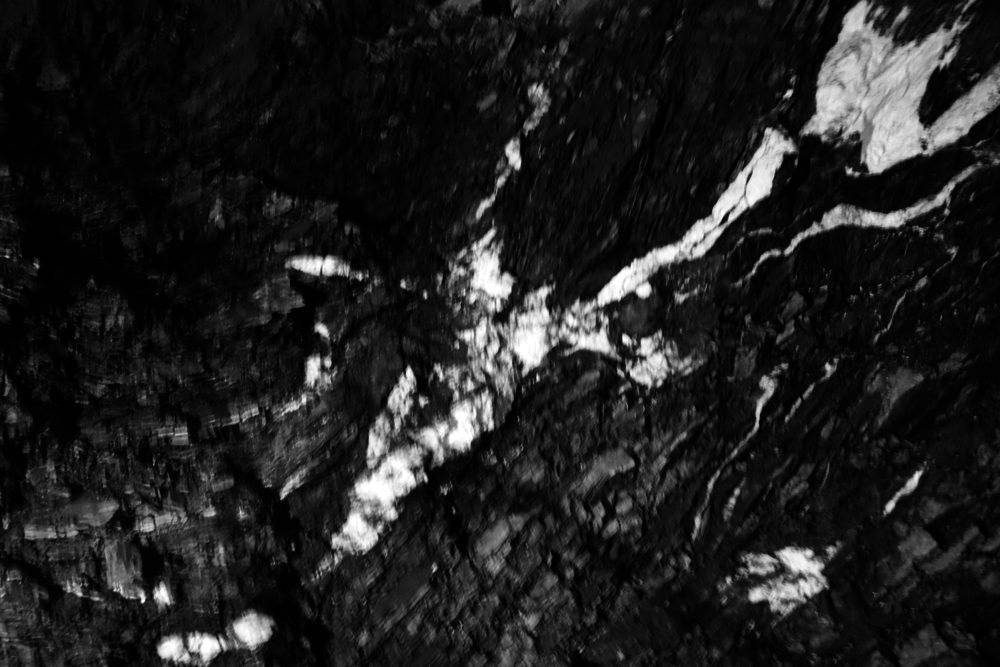
Figure 1: The surrounding rock of the tunnel
The shear test system of rock borehole was used for the in-situ rock strength test in the Changping tunnel. One measuring point was arranged on two sides of section DK61 + 285 of the tunnel and the other three points were arranged on the section DK61 + 275 of the tunnel. During the shear test, the internal block of the borehole collapsed and the probes were stuck several times, which indicated that the surrounding rock of the tunnel was in poor integrity, and the rock strength was mainly controlled by the joint plane. The test results are listed in Table 1.
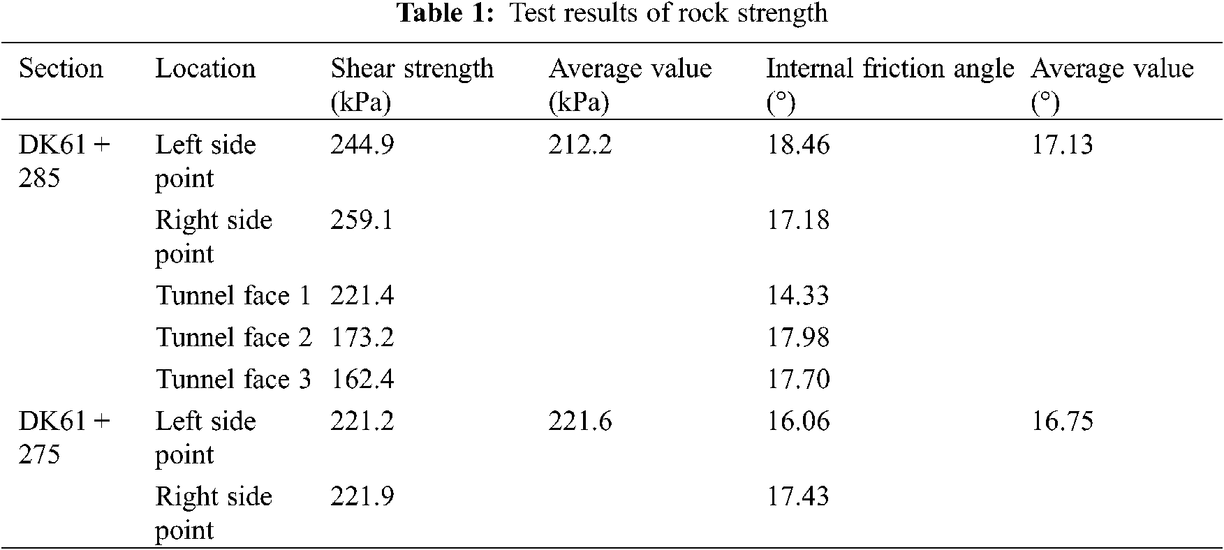
It can be seen from Table 1, the in-situ shear strength of the seven measuring points of the two sections is about 210–220 kPa, and the internal friction angle is about 17°. The uniaxial compressive strength is 0.57 MPa by the Jethwa formula and 1.30 MPa by the Hoek formula.
The tectonic movement was strong near the fault zone in this area, which was the main source of the horizontal ground stress in the tunnel.
The results of in-situ stress measurement by the hydraulic fracturing technique are shown in Table 2. As seen from Table 2, the relationship of the three principal stresses is σH > σV > σh, indicating the existence of the high horizontal tectonic stress. The ratio of the maximum horizontal to the vertical stress is between 1.06 and 1.33. The measured maximum stress is 25.09 MPa, and the orientation is N26°W to N62°W, which intersects with the tunnel axis N28°W at a small angle [21].

3.3 Failure Characteristics of Original Support
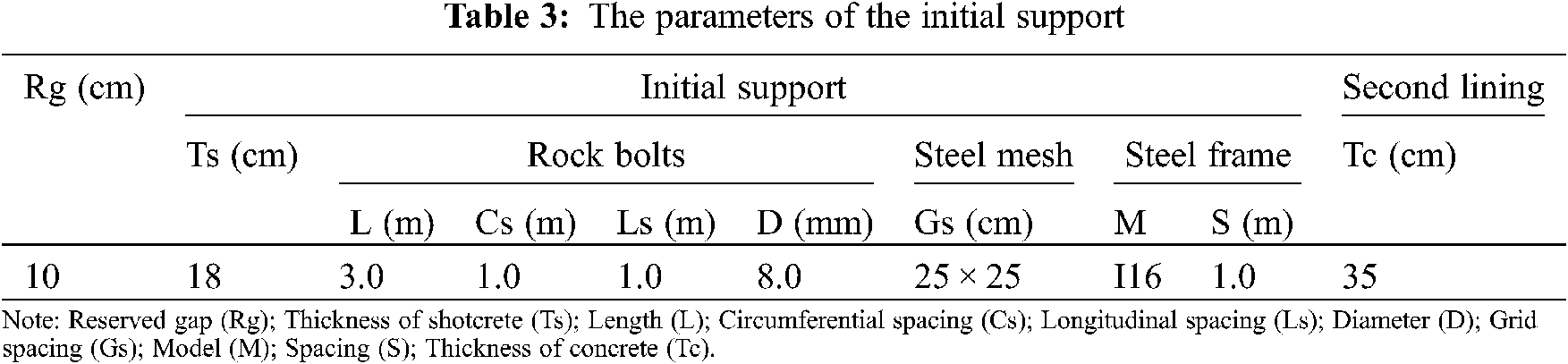
As shown in Fig. 2, the original tunnel section is straight wall-semicircular arch. The construction method was three-step excavation. Small pipe grouting in advance was used for the pre-supporting. The diameter of the arch pipe was 42 mm, the length of each pipe was 4 m, with a circumferential spacing of 0.5 m and a longitudinal spacing of 2.4 m. The composite lining was used in the tunnel. The primary support was bolt-shotcrete-steel mesh-frame, and the steel frame was connected by the diameter 25 mm bolt. The support parameters are listed in Table 3.
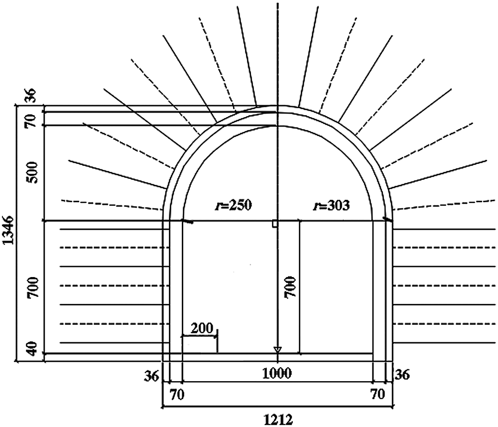
Figure 2: Design of the initial support (mm)
The monitoring data showed that the deformation of the tunnel occurred when the initial support was completed. After the completion of the initial support, the convergence was quick and the deformation tended to be stable after about 2 days. The deformation of the steel frame after the lower step excavation increased at the initial stage, then tended to be stable after 2 days. The average convergence rate of the surrounding rock was about 6 mm/d, and the maximum value was 56.7 mm/d.
The tunnel convergence was uneven and asymmetric, with a duration of about 90 days. The initial deformation was mainly horizontal convergence. The cumulative horizontal convergence of the inclined shaft was about 500–1000 mm, which accounted for about 44% of the inclined shaft.
The displacements of the ribs were asymmetric, and the displacement of the right rib was significantly greater than that of the left side. The settlement of the arch crown was generally small, ranging from 30 to 80 mm, and there was almost no settlement occurred at the arch foot. The failure of the support was concentrated in the concrete at the joint of steel frames and the side wall, forming the longitudinal cracks and the steel frames being twisted (Fig. 3a). The concrete on the right side of the arch crown was compressed and flaked off, and the steel frame was twisted (Fig. 3b). After the tunnel being stabilized, the scope of the loose circle was measured ranging from 5.2 to 5.4 m.

Figure 3: Concrete cracks and distortion of the steel frame of the wall and crown. (a) The side wall; (b) The arch crown
3.4 Causalitys for Instability of Original Support
The surrounding rock of the Changping tunnel was mainly phyllite, which strength was low and there were many joint planes. The tunnel was significantly affected by the horizontal tectonic stress. The uniaxial compressive strength of the rock was 1.3 MPa, which was 0.12 times to the maximum in-situ stress of 10.96 MPa at the section DK61 + 285 perpendicular to the tunnel axis. After the tunnel being excavation, the surrounding rock stress was redistributed, and the stress was far greater than the strength of the surrounding rock. When the surrounding rock acted on the initial support, the initial support was deformed, and the surrounding rock displacement was further increased. The surrounding rock stress was transferred to the deep rock mass, and the scope of the corresponding loose zones also expanded, which increased the squeezing deformation of the tunnel (Fig. 4).
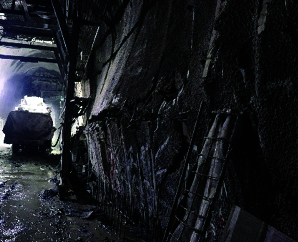
Figure 4: Failure modes of the surrounding rock
Although the original support method was reasonable, however, the support parameters were unreasonable. The spacing of the original steel frames was 1.0 m and whose model was I16. The original steel frames were not suitable for the Changping tunnel. The measured range of the loose circle of the tunnel was 5.2–5.4 m, and the length of the anchor bolts in the initial supporting was only 3.0 m, which was within the loose range of the surrounding rock. So the supporting of the anchor bolts could not be fully exerted. In the early stage of the construction, the construction time of the secondary linings was not controlled, resulted in the excessive deformation of the initial support and instability of the structure. As a rigid support, the thickness of the secondary lining was insufficient, which made the bearing capacity and stiffness of the secondary lining unable to meet the requirements of the large deformation tunnel.
The straight wall-semicircular arch tunnel was suitable for situations where the vertical stress was large and the horizontal one was small. When the horizontal stress was larger than the vertical one, both sides of the tunnel would be unstable. The deformation of the support was too small to fully release the stress of the surrounding rock, which was also one of the reasons for the instability of the original supporting structure.
3.5 New Support Scheme and Monitoring Plan
According to the large deformation mechanism of the Changping tunnel and the failure mode of the initial support, the field testing of a new support scheme was proposed. The tunnel section of 30 m in DK61 + 285 to DK61 + 255 was selected for testing and the two-step excavation method was adopted. The technical scheme of the test section was to reduce the stress of the surrounding rock, strengthen the surrounding rock, and improve the self-supporting capacity of the surrounding rock.
As shown in Fig. 5, the tunnel section was optimized to a curve and an inverted arch was set. The curved wall had strong resistance to the horizontal deformation and the stability of the tunnel floor was improved. The reserved deformation of the support was increased in the testing section. The deformation of the surrounding rock was controlled and the stress was released to prevent the damage of the initial support.
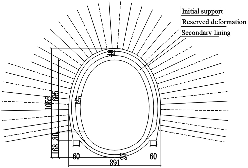
Figure 5: Design of the support in the test section (mm)
Small pipes grouting in advance was used in the pre-supporting, which could reduce the longitudinal and transverse spacing of the small pipes to 1.5 and 0.4 m, respectively. The small pipes were arranged in front of the tunnel at an inclination angle of 45°, with a diameter of 42 mm, a length of 3.0 m, and 25 pieces per ring. The specific supporting parameters are shown in Table 4.
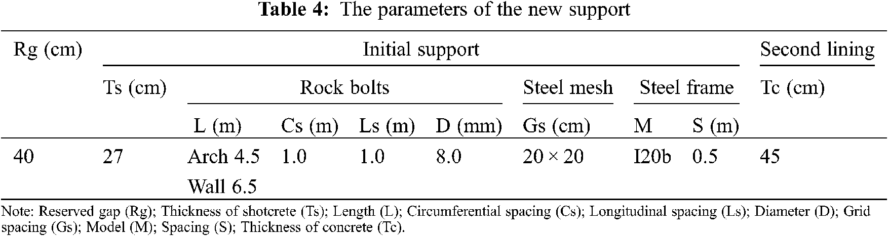
The anchor bolts with a length of 4.5 m were applied on the vault and those with a length of 6.5 m were applied at the wall waist. After the upper step being excavated, the construction of the short anchor bolts could effectively control the early deformation of the surrounding rock. Considering that the range of loose zone was 5.2–5.4 m, the length of the long anchor bolt was determined to be 6.5 m, and the anchorage section entered the elastic zone to improve the stability of the surrounding rock and utilize the strength of the deep rock mass.
As shown in Fig. 6, the steel frame model was adjusted to 120b, the spacing was reduced to 0.5 m, and the diameter 25 mm bars were used for connection to ensure the overall stability of the frame.
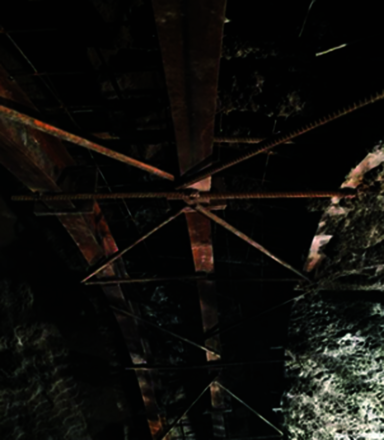
Figure 6: The connecting steel bars
The steel mesh spacing was reduced to 20 cm × 20 cm, which enhanced the initial support strength and mobilized the self-supporting capacity of the surrounding rock. When the deformation rate of the initial support stabilized at 1–2 mm/d, the secondary linings were applied to prevent it from being damaged by the excessive stress. The thickness of the secondary lining was increased to 45 cm, which improved the stiffness of the secondary lining.
The typical section DK61 + 275 was selected and the monitoring devices were arranged at the vault, the wall waist and the arch foot. The specific layout and parameters were shown in Fig. 7. The convergence of the tunnel was monitored. The double membrane pressure box was set between the surrounding rock and the initial support to measure the rock pressure. The strain gauge was embedded in the initial support concrete to measure the strain and then the stress of the initial support concrete was obtained by the conversion. The steel bar gauge was set on the anchor bolt to measure the anchor bolt stress. The frequency of measurement was once per day until that the deformation reached to stable.
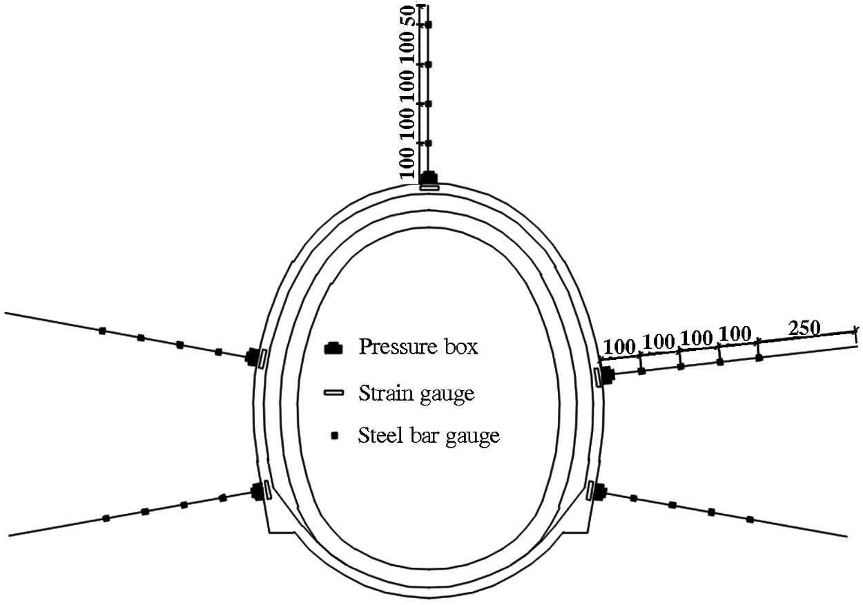
Figure 7: Arrangement of measuring points in the test section (mm)
4.1 Pressure of Surrounding Rock
It can be seen from Fig. 8, after the completion of the initial support, the pressure of the surrounding rock increased with time, while the growth rate increased firstly and then decreased, and tended to be stable after 10 days. The pressure of the surrounding rock was adjusted rapidly at the 25th day. The maximum pressure of the surrounding rock was located at the left arch foot. The pressure of the surrounding rock around the left wall decreased first and then increased, and the increment of other parts were small. The pressure of the surrounding rock at the left arch foot decreased at the 29th day, and it tended to be stable at about the 33rd day. According to the pressure distribution of the surrounding rock along the tunnel circumference, the maximum pressure was located at the right wall waist, the left symmetrical part was the minimum, and the pressure of the arch crown was the medium. The pressure of the surrounding rock on the right side was greater than that on the left side, which was consistent with the fact that the convergence on the right side was greater than that on the left side.
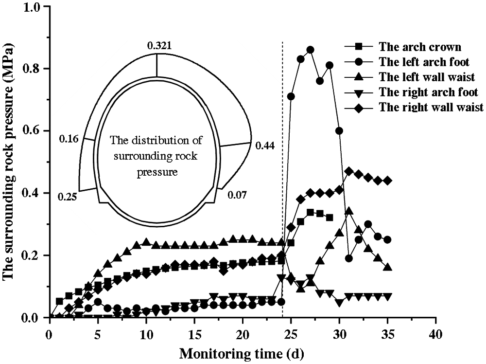
Figure 8: Pressure-time curves of the surrounding rock (DK61 + 275)
4.2 Concrete Stress of Initial Support
As seen from Fig. 9, the concrete stress of the initial support increased after the completion of the initial support and it tended to be stable after 8 days. The concrete stress of the initial support of the arch crown increased rapidly at the 25th day. The concrete stresses of the initial support of the right wall waist and right arch foot increased first and then decreased, and it decreased at the left wall waist. The concrete stress of the initial support tends to be stable at about the 33rd day. After the construction of the inverted arch, the horizontal convergence led to stress concentration in the arch crown. The concrete stress of the initial support is less than its compressive strength, and there is no large-scale cracking and spalling.
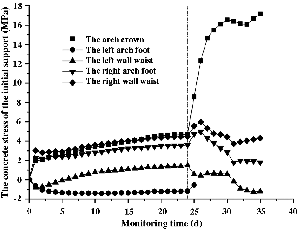
Figure 9: Stress-time curves of the initial support concrete (DK61 + 275)
Due to the damage of the reinforcement meters of the vaults, the data of the left and the right arch foot could not be obtained, therefore, only the data of the wall waists were analyzed. It can be seen from Fig. 10, the stress of the anchor bolts in the left and right wall waist reached the stability about 20 and 17 days, respectively. After the construction of the invert arch, the stress change of the anchor bolt reached the largest at 3.0 m from the right wall waist to the hole, which were small at 2.0 m of the right wall waist, 1.0, 3.0, and 4.0 m of the left wall waist. The stress of the anchor bolt tended to be stable after about 33 days [22].
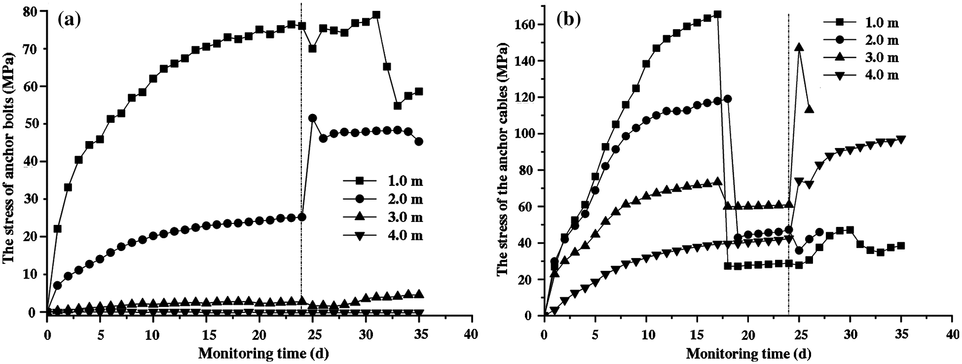
Figure 10: Stress-time curves of the anchor bolts (DK61 + 275). (a) The left wall waist; (b) The right wall waist
It can be seen from Fig. 11, the stress distribution of the anchor bolt on two wall waists was asymmetric, the right anchor bolt was significantly greater than that of the left one. The stress distribution of the anchor bolt was characterized by “small at ends and large in the middle” [23,24]. The maximum stress of the anchor bolt on the right wall waist was located at 1.0 m from the hole at the 15th day, 3.0 m at the 20th to the 25th day. The plastic zone of the right arch waist was about 3.0 m at the 25th day, which was smaller than that of 5.2–5.4 m measured previously, which showed that the stress of the anchor bolts was less than its tensile strength.
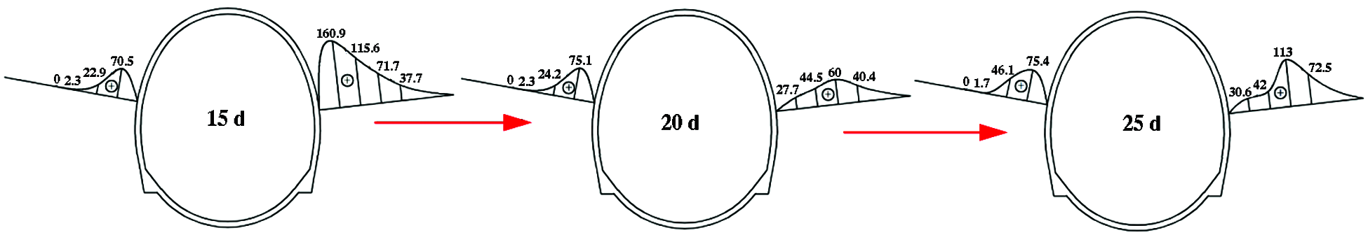
Figure 11: Stress distribution of anchor bolt along the depth (DK61 + 275) (MPa)
After adopting the new support scheme, the convergence process of the Changping tunnel was shown in Fig. 12, and the convergence displacement reached 333.3 mm. The reserved deformation of the new support scheme of the test section was 40 cm, and the large deformation of the soft rock did not affect the clearance of the tunnel. In the process of convergence, the construction of the inverted arches led to a sharp increase of the convergence, and the maximum deformation rate reached 37.2 mm/d. The monitoring results show that the new support scheme can effectively control the large deformation of the Changping tunnel.
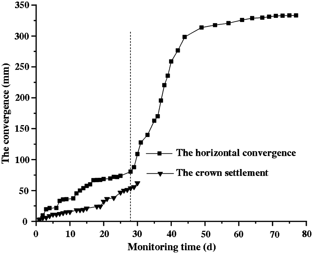
Figure 12: Convergence-time curves of the monitoring points (DK61 + 275)
To control the large deformation of the Changping tunnel, the deformation and failure mechanism of the original support were analyzed. The new support scheme was proposed and the on-site monitoring was carried out. The main conclusions are as following:
1. The horizontal convergence of the deformation in the tunnel is large and it is asymmetric convergence on the left and right waists, which is caused by the effect of the rock strength, the in-situ stress, and the parameters of the support scheme.
2. When the maximum horizontal stress intersects with the structural plane of the surrounding rock at a small angle, the surrounding rock produces the slide and shear failure, which results in the pressure difference and uneven convergence of both sides of the tunnel.
3. The curved-wall design is better than the straight-wall one, and the combined support of the long and short anchor bolts is also helpful to control the deformation of the surrounding rock. The new support scheme can effectively control the large deformation of the Changping tunnel.
Acknowledgement: This study expresses gratitude to the construction staff for their active cooperation in field testing and monitoring of experimental data.
Funding Statement: This study was financially supported by the National Natural Science Foundation of China (51774112), the Fundamental Research Funds for the Universities of Henan Province (NSFRF200202).
Conflicts of Interest: The authors declare that they have no conflicts of interest to report regarding the present study.
1. Kanji, M. A. (2014). Critical issues in soft rocks. Journal of Rock Mechanics and Geotechnical Engineering, 6, 186–195. DOI 10.1016/j.jrmge.2014.04.002. [Google Scholar] [CrossRef]
2. Hoek, E., Marinos, P. (2000). Predictingtunnel squeezing problems in weak heterogeneous rock masses. Tunnels & Tunnelling International, 32(11), 45–51. [Google Scholar]
3. He, M. C. (2014). Latest progress of soft rock mechanics and engineering in China. Journal of Rock Mechanics and Geotechnical Engineering, 6, 165–179. DOI 10.1016/j.jrmge.2014.04.005. [Google Scholar] [CrossRef]
4. Chen, Z. J. (1982). The mechanical problems for the long-term stability of underground galleries. Chinese Journal of Rock Mechanics and Engineering, 1(1), 1–20. [Google Scholar]
5. Li, G., Ma, F. S., Guo, J., Zhao, H. J., Liu, G. (2020). Study on deformation failure mechanism and support technology of deep soft rock roadway. Engineering Geology, 264, 1–16, 105262. DOI 10.1016/j.enggeo.2019.105262. [Google Scholar] [CrossRef]
6. Yang, S. Q., Chen, M., Jing, H. W., Chen, K. F., Meng, B. (2017). A case study on large deformation failure mechanism of deep soft rock roadway in Xin’An coal mine, China. Engineering Geology, 217, 89–101. DOI 10.1016/j.enggeo.2016.12.012. [Google Scholar] [CrossRef]
7. Alonso, E. E., Berdugo, I. R., Tarragona, A. R. (2013). Extreme expansive phenomena in anhydritic-gypsiferous claystone: The case of lilla tunnel. Geotechnique, 63(7), 584–612. DOI 10.1680/geot.12.P.143. [Google Scholar] [CrossRef]
8. Meng, L. B., Li, T. B., Jiang, Y., Wang, R., Li, Y. R. (2013). Characteristics and mechanisms of large deformation in the Zhegu mountain tunnel on the Sichuan-Tibet highway. Tunnelling and Underground Space Technology, 34, 157–164. DOI 10.1016/j.tust.2013.03.009. [Google Scholar] [CrossRef]
9. Asghar, R., Lohrasb, F., Mohammad, D. (2017). Squeezing rock conditions at phyllite-slate zone in golab water conveyance tunnel, Iran: A case study. Journal of Central South University, 24(10), 2475–2485. DOI 10.1007/s11771-017-3659-6. [Google Scholar] [CrossRef]
10. Fuente, M. D. L., Sulem, J., Taherzadeh, R., Subrin, D. (2019). Tunneling in squeezing ground: Effect of the excavation method. Rock Mechanics and Rock Engineering, 53, 601–623. DOI 10.1007/s00603-019-01931-4. [Google Scholar] [CrossRef]
11. Mezger, F., Ramoni, M., Anagnostou, G. (2018). Options for deformable segmental lining systems for tunnelling in squeezing rock. Tunnelling and Underground Space Technology, 76, 64–75. DOI 10.1016/j.tust.2017.12.017. [Google Scholar] [CrossRef]
12. Sharma, S., Muthreja, I. L., Yerpude, R. R. (2020). Application and comparison of squeezing estimation methods for himalayan tunnels. Bulletin of Engineering Geology and the Environment, 79, 205–223. DOI 10.1007/s10064-019-01530-1. [Google Scholar] [CrossRef]
13. Cao, C. Y., Shi, C. H., Lei, M. F., Yang, W. C., Liu, J. W. (2018). Squeezing failure of tunnels: A case study. Tunnelling and Underground Space Technology, 77, 188–203. DOI 10.1016/j.tust.2018.04.007. [Google Scholar] [CrossRef]
14. Aksoy, C. O., Ogul, K., Topal, I., Ozer, S. C., Ozacar, V. et al. (2012). Numerical modeling of non-deformable support in swelling and squeezing rock. International Journal of Rock Mechanics and Mining Sciences, 52, 61–70. DOI 10.1016/j.ijrmms.2012.02.008. [Google Scholar] [CrossRef]
15. Tao, Z. G., Cao, J. D., Yang, L., Guo, A. P., Huang, R. F. et al. (2020). Study on deformation mechanism and support measures of soft surrounding rock in muzhailing deep tunnel. Advances in Civil Engineering, 2020, 1–14, 9367916. DOI 10.1155/2020/9367916. [Google Scholar] [CrossRef]
16. Wang, S. R., Li, C. L., Liu, Z. W., Fang, J. B. (2014). Optimization of construction scheme and supporting technology for HJS soft rock tunnel. International Journal of Mining Science and Technology, 24(6), 847–852. DOI 10.1016/j. ijmst.2014.10.018. [Google Scholar]
17. Wang, F., Kaunda, R. (2019). Assessment of rockburst hazard by quantifying the consequence with plastic strain work and released energy in numerical models. International Journal of Mining Science and Technology, 29(1), 93–97. DOI 10.1016/j.ijmst.2018.11.023. [Google Scholar] [CrossRef]
18. Oh, J., Moon, T. (2017). Seismic design of a single bored tunnel: Longitudinal deformations and seismic joints. Rock Mechanics and Rock Engineering, 51, 893–910. DOI 10.1007/s00603-017-1366-0. [Google Scholar] [CrossRef]
19. Wang, S. R., Xiao, H. G., Hagan, P., Zou, Z. S. (2017). Mechanical behavior of fully-grouted bolt in jointed rocks subjected to double shear tests. Dyna, 92(6), 314–320. DOI 10.6036/8325. [Google Scholar] [CrossRef]
20. Kulatilake, P. H. S. W., Wu, Q., Yu, Z. X., Jiang, F. X. (2013). Investigation of stability of a tunnel in a deep coal mine in China. International Journal of Mining Science and Technology, 23(4), 579–589. DOI 10.3969/j.issn.2095-2686.2013.04.018. [Google Scholar] [CrossRef]
21. Zhang, X. B., Jia, Z. W. (2019). Influence of ground stress on coal seam gas pressure and gas content. Fluid Dynamics & Materials Processing, 15(1), 53–61. DOI 10.32604/fdmp.2019.04779. [Google Scholar] [CrossRef]
22. Zhao, R. R., Feng, Z. J., Jiang, G., Wang, F. C., Zhang, Y. D. et al. (2021). A pull-out test study on the working state of fully grouted bolts. Fluid Dynamics & Materials Processing, 17(2), 441–453. DOI 10.32604/fdmp.2021.010595. [Google Scholar] [CrossRef]
23. Wang, S. R., Xiao, H. G., Zou, Z. S., Cao, C., Wang, Y. H. et al. (2019). Mechanical performances of transverse rib bar during pull-out test. International Journal of Applied Mechanics, 11(5), 1–15, 1950048. DOI 10.1142/S1758825119500480. [Google Scholar] [CrossRef]
24. Wang, S. R., Wang, Y. H., Wang, Z. L., Gong, J., Li, C. L. (2021). Anchoring performances analysis of tension-torsion grouted anchor cable under free and non-free rotation conditions. Dyna, 96(2), 166–172. DOI 10.6036/9985. [Google Scholar] [CrossRef]
 | This work is licensed under a Creative Commons Attribution 4.0 International License, which permits unrestricted use, distribution, and reproduction in any medium, provided the original work is properly cited. |