| Fluid Dynamics & Materials Processing |
DOI: 10.32604/fdmp.2022.015746
ARTICLE
Optimization of Sound Absorption and Insulation Performances of a Dual-Cavity Resonant Micro-Perforated Plate
1State Grid Hunan Electric Power Co., Ltd., Electric Power Research Institute, Changsha, 410000, China
2State Grid Corporation of China Power Facilities Noise and Vibration Laboratory, Changsha, 410000, China
3North China Electric Power University, Department of Environmental Science and Engineering, Hebei Provincial Key Laboratory of Coal-Fired Power Station Flue Gas Multi-Pollution Cooperative Control, Baoding, 071003, China
4North China Electric Power University, Key Laboratory of Regional Energy System Optimization Ministry of Education, Beijing, 102206, China
*Corresponding Author: Zhaofeng Guo. Email: 52351314@ncepu.edu.cn
Received: 10 January 2021; Accepted: 26 March 2021
Abstract: This study investigates a dual-cavity resonant composite sound-absorbing structure based on a micro-perforated plate. Using the COMSOL impedance tube model, the effects of various structural parameters on sound absorption and sound insulation performances are analyzed. Results show that the aperture of the micro-perforated plate has the greatest influence on the sound absorption coefficient; the smaller the aperture, the greater is this coefficient. The thickness of the resonance plate has the most significant influence on the sound insulation and resonance frequency; the greater the thickness, the wider the frequency domain in which sound insulation is obtained. In addition, the effect of filling the structural cavity with porous foam ceramics has been studied, and it has been found that the porosity and thickness of the porous material have a significant effect on the sound absorption coefficient and sound insulation, while the pore size exhibits a limited influence.
Keywords: Micro perforated plate; double cavity; compound resonance structure; sound absorption coefficient; sound insulation
With societal development and the increasing awareness of the need for environmental protection, the study of noise pollution has attracted considerable attention in recent years. Low-frequency noise has the characteristics of long distance of propagation and small attenuation, and can lead to several harmful effects. Conventional materials have a limited ability to control low-frequency noise. Thus, due to their excellent low-frequency acoustic performance, micro-perforated plates have been extensively studied by scientific researchers [1–3]. In micro-perforated plates, the diameter of perforation is less than 1 mm; therefore, the broadband sound absorption effect is better than the resonance sound absorption in conventional perforated plates. Micro-perforated plates have several advantages such as simple structure, environmental friendliness, light weight, low cost, and corrosion resistance [4–6].
The micro-perforated plate theory was first proposed by Maa Dah-you. Considering the sound absorption mechanism in micro perforated plates, the micro-holes on the thin plate have acoustic impedance similar to that of air; therefore, the air column can consume energy produced by friction using these micro-holes; thus, making it a high-resistance, low-quality resonance sound absorber. However, the main disadvantage of the microplate is the narrow sound absorption band, which limits its application in practical engineering [7–9]. Several scientific researchers have attempted to increase the sound absorption frequency band [10–13]. Yang et al. [14] proposed a novel light sound-insulation composite plates made from aluminum honeycomb cores and microperforated panels and included GSGN film and sawdust-board. Their results show that the weighted sound-insulation index can reach 58.41 dB while the density is only 0.37 g/mm3. Hu et al. [15] developed a composite resonance plate sound barrier composed of micro-perforated plates, resonance plates, damping layers, and galvanized steel plates, which greatly improved the sound insulation and sound absorption performance of low-frequency noise in substations. The result shows that when the thickness is 10 cm, the average sound absorption coefficient of double- and three-layer composite resonances for the frequencies of 500 Hz and below can reach 0.48–0.64 and 0.49–0.72, respectively. The sound absorption coefficient for 100 Hz frequency can reach 0.18–0.34 and 0.20–0.38, respectively. Liu et al. [16], aiming at poor efficiency of the traditional materials in low-mid frequency sound absorption and its narrow bandwidth, present an ultra-broadband acoustic metamaterial whose basic cell is constructed by dividing the original neck of a Helmholtz resonator into multiple smaller ones, and the neck panel becomes into a micro-perforated panel that can achieve a near-perfect continuous absorption within 380–3600 Hz, with a thickness of only 7.2 cm. The acoustic metamaterial can obtain multiple excellent high-order absorption peaks compared to traditional micro-perforated plates. Gai et al. [17], in order to improve the low-frequency sound absorption performance of the single-layer micro-perforated plate sound-absorbing structure, designed an L-shaped split back cavity micro-perforated plate sound-absorbing structure, which greatly improves the low-frequency sound absorption performance of the single-layer micro-perforated plate structure, and significantly broadens the absorption bandwidth of a single-layer structure of the micro perforated plate.
However, compared with broadband noise reduction materials, micro-perforated plates have a narrower sound absorption frequency band, and there is limited research on its sound insulation [18–21]. Therefore, this study proposes a dual-cavity resonance composite sound-absorbing and insulating plate structure based on micro-perforated plates, and simulates its acoustic performance based on the COMSOL impedance tube model. Through the principle of controlling variables, the influence of structural parameters such as micro-perforated plate thickness, aperture, hole spacing, cavity thickness, resonance plate thickness, and damping thickness on the sound absorption coefficient and sound insulation of the composite sound-absorbing and insulating structure is mainly analyzed. The structural parameters of the optimized composite panel are finally determined, so that it has better sound absorption performance and higher sound insulation.
2 Structure and Simulation Methods
2.1 Double-Cavity Composite Sound-Absorbing and Insulating Structure Based on Micro-Perforated Plates
Based on the theory of micro-perforated plate resonance sound absorption, this study proposes a double-cavity composite sound-absorbing and insulating structure, which has good low-frequency sound absorption and sound insulation performance, and is suitable for low-frequency noise control. The structural diagram is shown in Fig. 1.
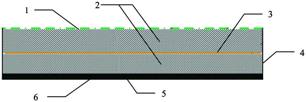
Figure 1: Structure of the double cavity composite resonance plate (1: micro-perforated plate (aluminum); 2: cavity; 3: resonance plate (aluminum); 4: side wall plate; 5: damping coating layer; 6: bottom plate (steel))
2.2 COMSOL Impedance Tube Model
In this study, a simulation model of the impedance tube is established based on COMSOL. The length of impedance tube is 1 m, its diameter is 0.1 m, and the cut-off frequency is 1600 Hz. The simulation model is shown in Fig. 2. The sound source is on the side of the impedance tube, and the composite sound-absorbing and insulating structure is placed on the opposite side of the sound source. The size is the same as the cross-section of the impedance tube. The sound absorption coefficient is calculated by the transfer function method, and the sound insulation is derived from the sound absorption coefficient and transmission loss formula.
In the simulation model, the resonance board defines the simply supported boundary, and the other layers of the dual-cavity resonant micro-perforated plate are defined as free boundaries. The model is meshed to characterize the geometric model and solution domain of the simulated material. After considering different materials and types of structures, a suitable model for the sound absorption and insulation performance of the simulated material is constructed for finite element solution.
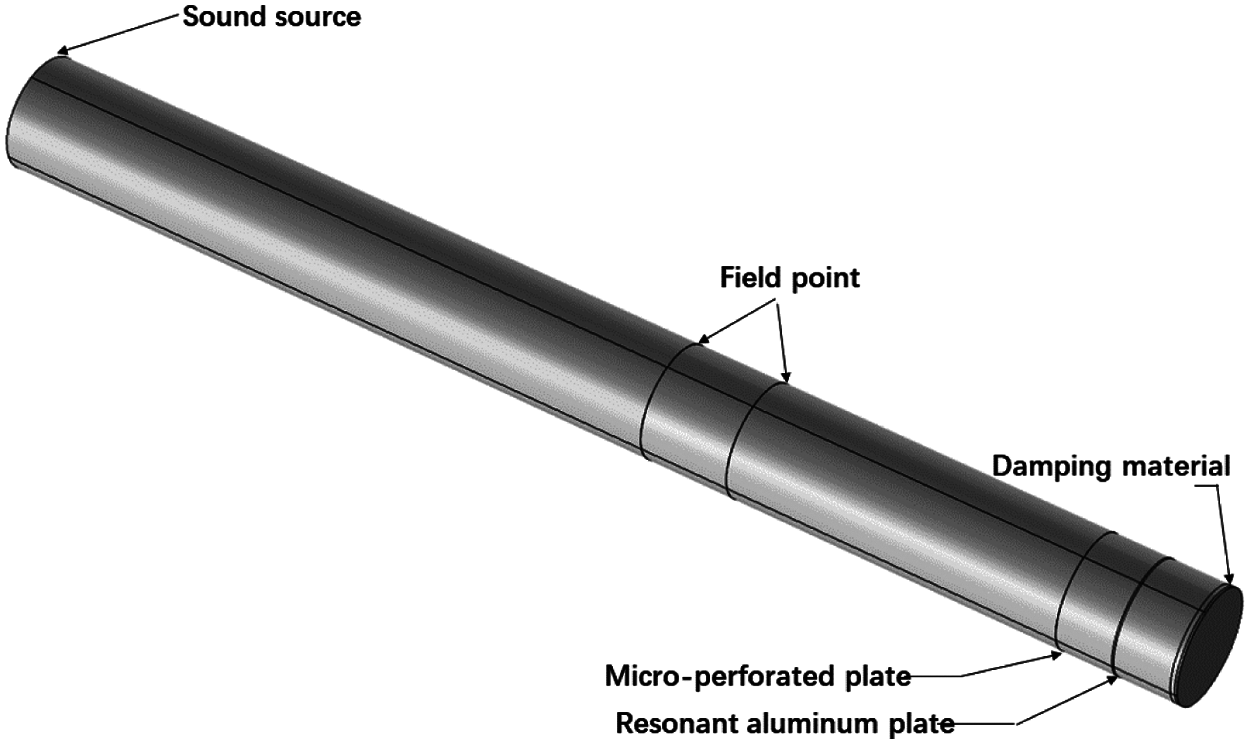
Figure 2: Simulation model of impedance tube
2.3 Simulation Model Verification
(1) Relative acoustic impedance ratio of the sound-absorbing structure of the micro-perforated plate [22–24]
Assuming that the area of the perforation is S, the area of the perforated plate is S0, and the thickness of the air layer is D, the volume of the cavity occupied by each perforation is
The relative acoustic impedance ratio of the sound absorption structure of the micro-perforated plate for a unit area of the plate:
(2) Sound absorption coefficient of the sound-absorbing structure of the micro-perforated plate at normal incidence [25–27]
In the equivalent circuit, according to the Thevenin theory, the sound pressure 2pi on the board is considered as the source when the board is completely reflected (open circuited). The reflection coefficient is r, the acoustic impedance ratio of the micro-perforated plate is
where
where d is the diameter of the perforation (in mm); t is the thickness of the plate (in mm); b is the hole spacing (in mm); D is the thickness of the cavity behind the plate (in m); p is the perforation rate (%);
The resonance frequency satisfies:
Maximum sound absorption coefficient:
In order to verify the correctness of the simulation model, the theoretical value of the sound absorption coefficient of the micro-perforated plate was compared with the simulated value. Each parameter of the micro-perforated plate is set to have a hole diameter of 0.5 mm, a plate thickness of 0.5 mm, a porosity of 1%, and a cavity thickness of 30 mm. The result is shown in Fig. 3. It is evident that the theoretical value of the micro-perforated plate is highly consistent with the simulated value, which verifies the reliability of the simulation results in this study.
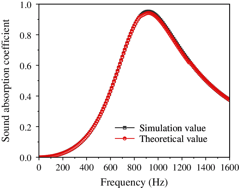
Figure 3: Comparison between the theoretical and simulated values of the sound absorption coefficient of the micro-perforated plate
3.1 Influence of the Parameters of the Composite Resonance Plate on Its Sound Absorption Coefficient
A micro-perforated plate + cavity + resonance plate + cavity + damping layer bottom plate model is established in the impedance tube model. The thickness d1 of the micro-perforated plate (aluminum plate) can be 0.2, 0.5, and 0.8 mm. The aperture a can be 0.3, 0.4, 0.5, and 0.6 mm. The hole spacing b can be 1, 3, 5, and 7 mm. The cavity thickness D can be 30, 40, and 50 mm. The thickness d2 of the middle resonant plate (aluminum plate) can be 0.5, 1, and 1.5 mm. The thickness of the damping layer d3 can be 2, 4, and 6 mm. The thickness of the bottom plate (steel plate) d4 is fixed at 2 mm. In the model, the parameters of the damping layer are set as follows: the damping coefficient is 0.6, the Young’s modulus is 100 Mpa, the shear modulus is 30 Mpa, and the density is 1.4 g/cm3.
The initial parameters of the composite board structure are set as: d1 = 0.5 mm, a = 0.5 mm, b = 3 mm, D = 40 mm, d2 = 1 mm, d3 = 4 mm, and d4 = 2 mm. The controlled variable method is adopted to change the value of a certain parameter of the model, and the influence law of each parameter on the structure sound absorption coefficient is obtained, as shown in Figs. 4–9.
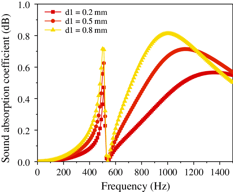
Figure 4: Effect of thickness of the micro-perforated plate on the sound absorption coefficient of the composite resonance plate
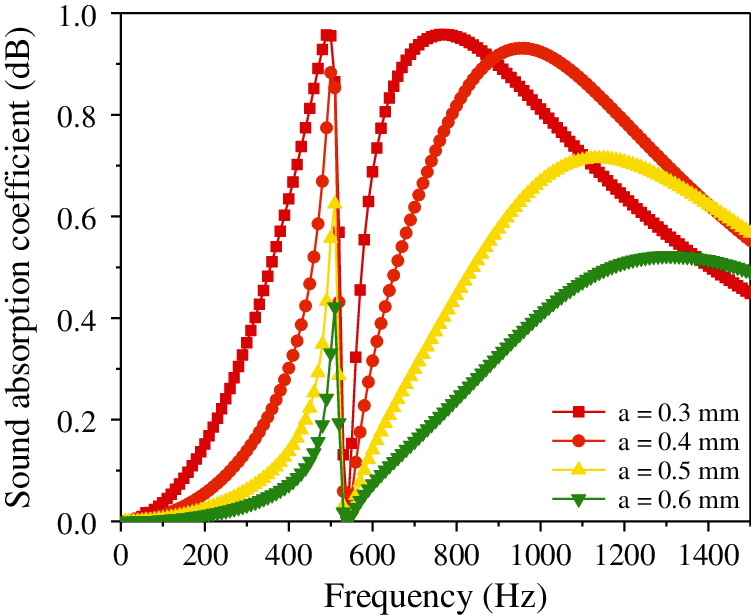
Figure 5: Effect of aperture of the micro-perforated plate on the sound absorption coefficient of the composite resonance plate
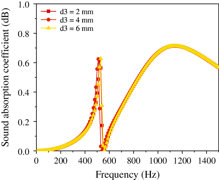
Figure 6: Effect of thickness of the damping layer on the sound absorption coefficient of the composite resonance plate
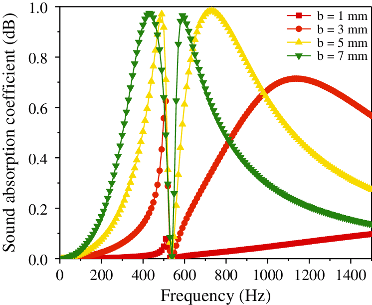
Figure 7: Effect of hole spacing on the sound absorption coefficient of the composite resonance plate
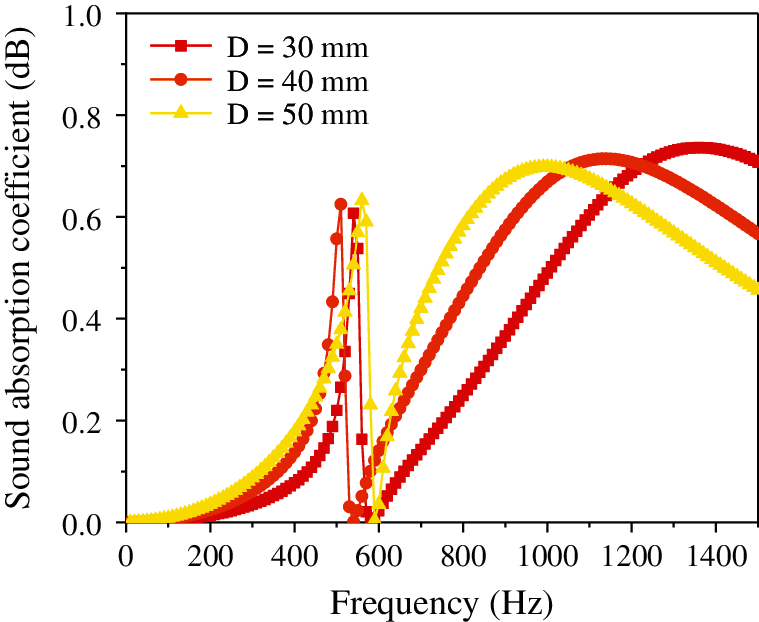
Figure 8: Effect of cavity thickness on the sound absorption coefficient of the composite resonance plate
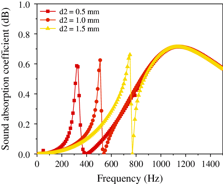
Figure 9: Effect of thickness of the resonance plate on the sound absorption coefficient of the composite resonance plate
It is evident from Fig. 4 that as the thickness of the microporous plate increases, the peak frequency of the sound absorption coefficient remains unchanged at 500 Hz, and the sound absorption coefficient increases (0.120–0.175–0.231). Then it decreases suddenly, reaching a valley at approximately 0 when the frequency reaches 510 Hz. Fig. 5 shows that as the aperture decreases, the sound absorption coefficient gradually increases (0.41–0.633–0.889), but the peak and valley frequencies remain approximately unchanged. Additionally, Fig. 6 illustrates that with the continuous increase in the damping thickness, the sound absorption coefficient remains approximately unchanged (0.1755–0.1755–0.1767). Fig. 7 illustrates that with the continuous increase in the hole spacing, the resonant frequency remains unchanged and stable at approximately 500 Hz; however, the sound absorption coefficient gradually increases (0.012–0.068–0.175–0.328–0.489). Fig. 8 shows that as the thickness of the cavity increases, the sound absorption coefficient remains approximately constant (0.189–0.175–0.197), but the resonance frequency gradually shifts to a lower value. Finally, Fig. 9 illustrates that with the continuous increase in the thickness of the resonance plate, the sound absorption coefficient increases slightly (0.165–0.175–0.193), and the resonance frequency gradually shifts to the higher value (310 Hz–500 Hz–730 Hz).
Analysis of the above data shows that the aperture and hole spacing have the greatest impact on the sound absorption coefficient, and the smaller the hole diameter, the larger the hole spacing, and the greater the sound absorption coefficient. The thickness of the resonant plate has the most significant influence on the resonant frequency; the smaller the thickness, the lower the resonance frequency. The damping thickness has no considerable effect on the sound absorption coefficient. In order to make the sound absorption coefficient of the composite micro-perforated plate larger and at a lower frequency, the aperture and the thickness of the resonance plate can be reduced, and the thickness of the micro-perforated plate, hole spacing, and cavity thickness can be increased.
3.2 Influence of the Parameters of the Composite Resonance Plate on Its Sound Insulation
Defining the incident sound pressure at P0 = 1 Pa, the reflected sound pressure P1 is measured by the impedance tube model, the outgoing sound pressure P2 = P0 – (aP0 + P1), keeping the other geometric parameters of the composite resonance plate unchanged, and changing a single variable of the structure. From the sound insulation formula: TL = 20 log (P2/P0), the relationship between this variable and the sound insulation of the composite resonance plate is obtained by simulated calculation, as shown in Figs. 10–15.
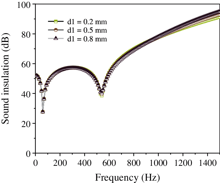
Figure 10: Effect of thickness of the micro-perforated plate on the sound insulation of the composite resonance plate
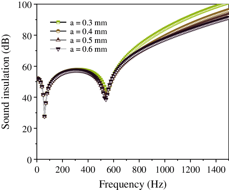
Figure 11: Effect of aperture of the micro-perforated plate on the sound insulation of the composite resonance plate
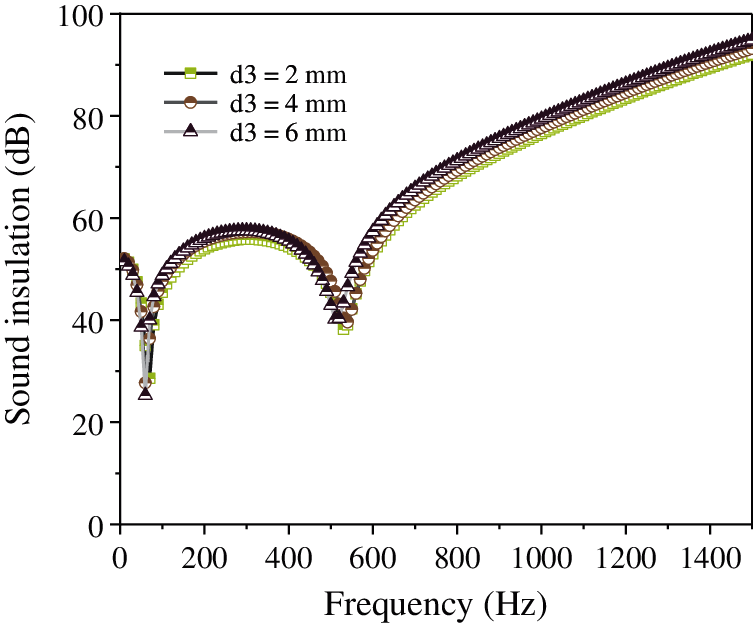
Figure 12: Effect of thickness of the damping layer on the sound insulation of the composite resonance plate
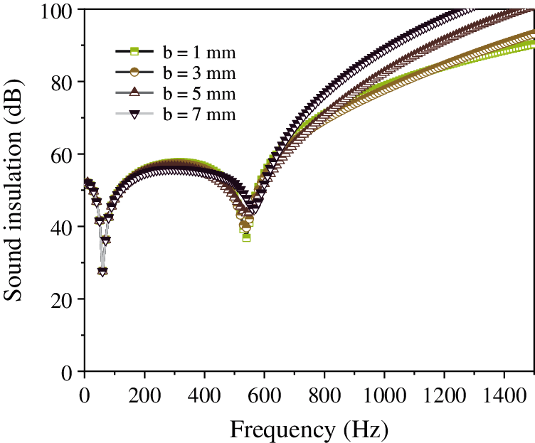
Figure 13: Effect of hole spacing on the sound insulation of the composite resonance plate
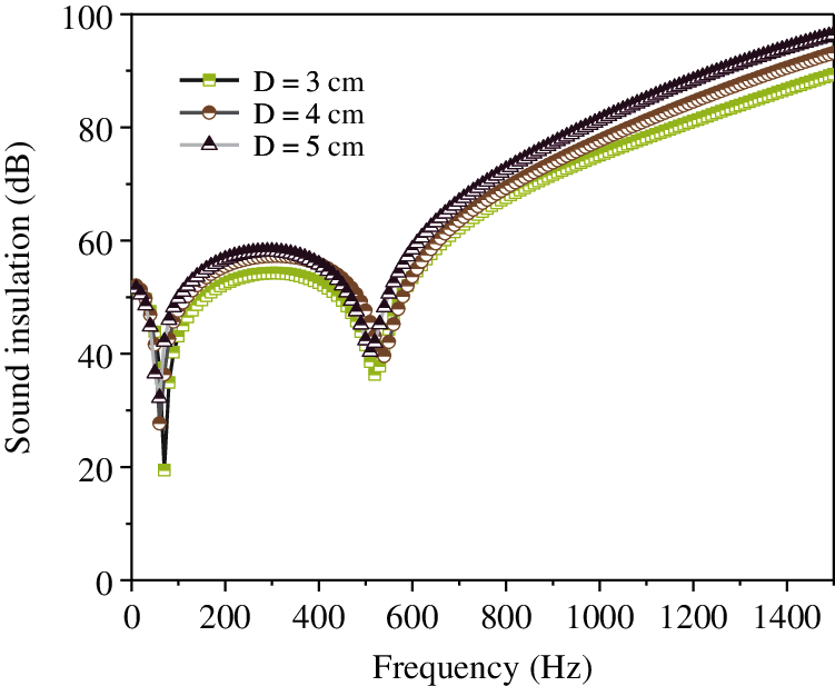
Figure 14: Effect of cavity thickness on the sound insulation of the composite resonance plate
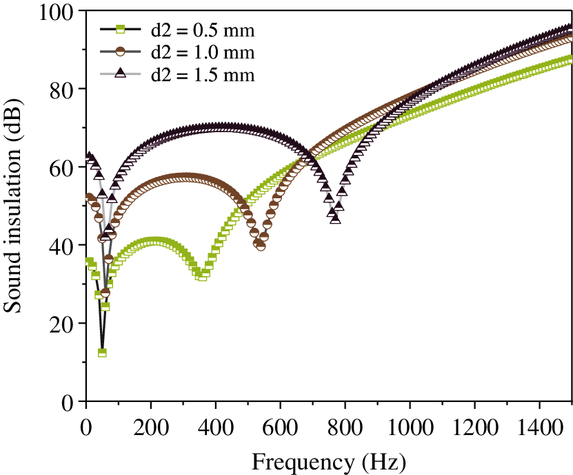
Figure 15: Effect of thickness of the resonance plate on the sound insulation of the composite resonance plate
Fig. 10 shows that with the continuous increase in the thickness of the micro perforated plate, the sound insulation of the composite resonant plate is almost unchanged. In addition, the thickness of the micro perforated plate has little effect on the sound insulation of the resonant plate. Moreover, it is evident from Fig. 11, that with the continuous decrease in the aperture, the sound insulation is almost unchanged; however, when the aperture = 0.2 mm, the sound insulation is significantly improved from 58 dB to 70 dB. Further, Fig. 12 shows that with the continuous increase in the thickness of the damping layer, the sound insulation peak, along with the second sound insulation valley and the sound insulation volume, remain unchanged. Fig. 13 illustrates that with the continuous increase in the hole spacing, the sound insulation of the composite resonance plate exhibits a certain decrease, but it is considerably small. Additionally, Fig. 14 shows that as the thickness of the cavity increases, the amount of sound insulation gradually increases (56 dB–58 dB–60 dB). Finally, Fig. 15 illustrates that as the thickness of the resonance plate continues to increase, the average sound insulation capacity gradually increases, the sound insulation peak also rises, and the first sound insulation valley is unchanged, but the second insulation valley gradually moves to the high frequency.
The analysis of the above data shows that the thickness of the micro-perforated plate, the thickness of the damping layer, and the hole spacing have little effect on the sound insulation. When the aperture is 0.2 mm, the sound insulation is significantly improved, and the thickness of the cavity and the sound insulation are gradually increased. The thickness of the resonant plate has a considerable effect on the sound insulation. The greater the thickness, the higher the resonance frequency. In order to improve sound insulation and lower frequency of the composite micro-perforated plate, the aperture and the thickness of the resonance plate can be reduced, while the other three parameters are based on the data of the sound absorption coefficient.
3.3 Effect of Filling the Cavity with SiC Porous Material on the Sound Absorption and Insulation Performance of the Composite Resonance Plate
In order to study the acoustic performance of the cavity filled with porous materials, the cavity was filled with porous materials on the basis of the original finite element model. The influence of the parameters of SiC foam ceramic porous material on the sound absorption coefficient can be seen in Figs. 16–18.
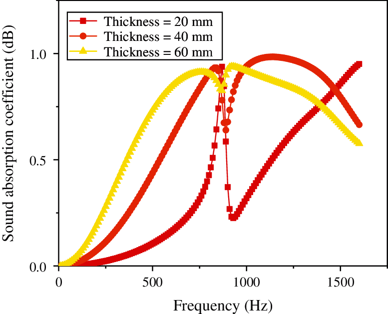
Figure 16: Effect of the porosity of foam ceramic porous material (SiC) on the sound absorption coefficient
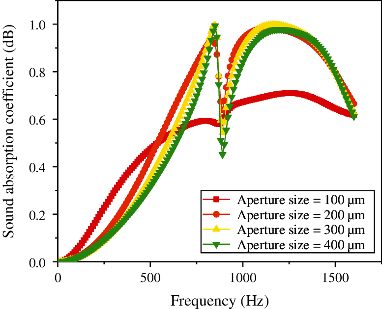
Figure 17: Effect of the thickness of foam ceramic porous material (SiC) on the sound absorption coefficient
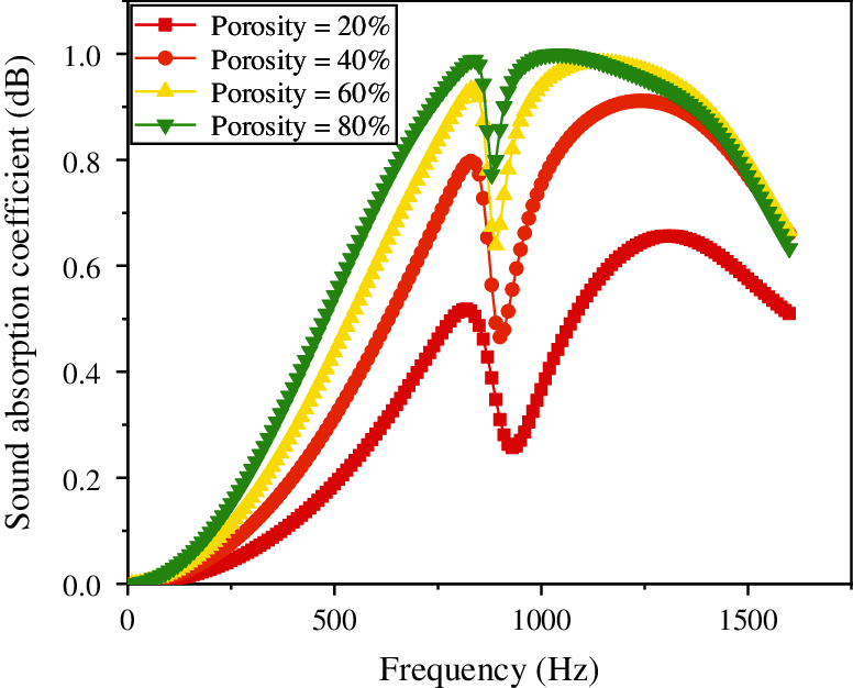
Figure 18: Effect of the pore size of foam ceramic porous material (SiC) on the sound absorption coefficient
From Fig. 16, it is evident that the porosity of porous materials continues to increase along with the sound absorption coefficient, reaching a peak at approximately 800 Hz, subsequently dropping to the first trough, and finally rising to the second peak. Finally, it is shown that when the porosity is 80%, the sound absorption coefficient increases more significantly. Fig. 17 shows that with the continuous increase in the thickness of the porous material, the sound absorption coefficient also continues to increase; however, there is a substantial decline at approximately 800 Hz, after which it continues to increase. It is concluded that when the thickness is 60 mm, the sound absorption coefficient in the low frequency region is improved more significantly. Additionally, Fig. 18 illustrates that as the pore size of the porous material increases, the sound absorption coefficient tends to increase; however, when the pore size is 200 μm, the sound absorption coefficient is the largest at low frequencies.
The influence of the parameters of SiC foam ceramic porous material on the sound insulation can be seen in Figs. 19–21.
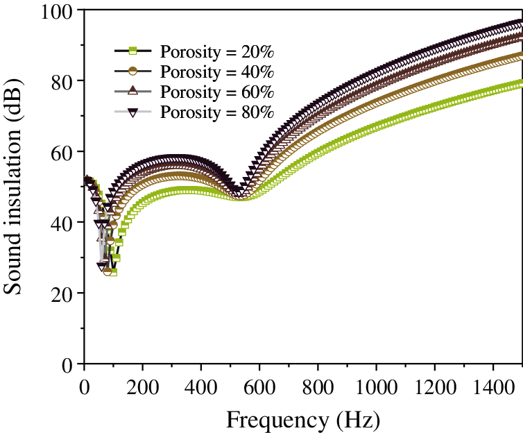
Figure 19: Effect of the porosity of the foamed ceramic porous material (SiC) on the sound insulation of the composite resonance plate
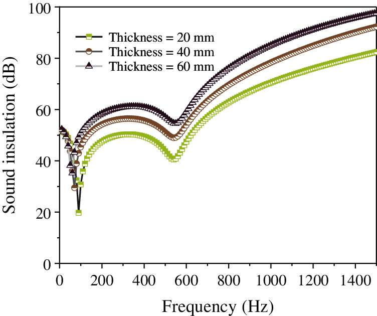
Figure 20: Effect of the thickness of the foamed ceramic porous material (SiC) on the sound insulation of the composite resonance plate
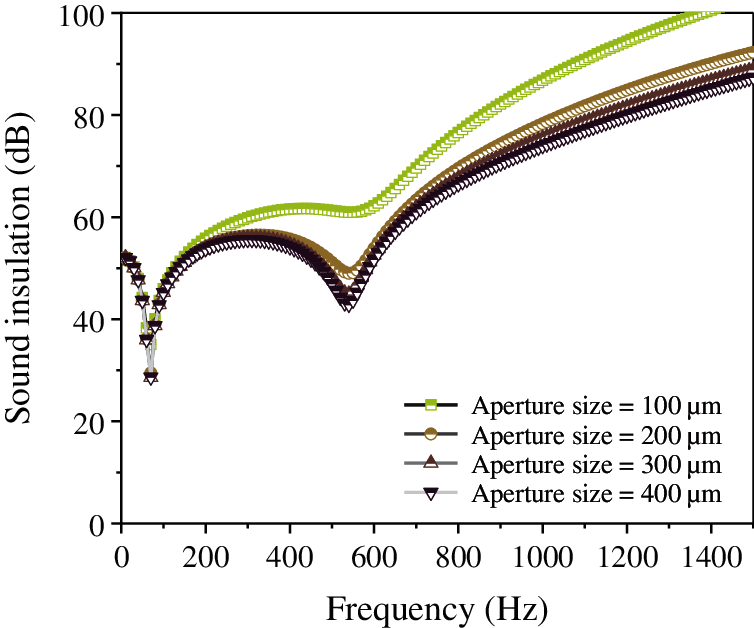
Figure 21: Effect of the pore size of the foamed ceramic porous material (SiC) on the sound insulation of the composite resonance plate
Fig. 19 shows that as the porosity of the porous material increases, the sound insulation of the composite resonant plate gradually increases. There is a trough approximately 100 Hz, after which the increase continues, reaching a second trough approximately 500 Hz. Nonetheless, the overall trend is rising. From Fig. 20, it is evident that as the thickness of the porous material increases, the sound insulation of the composite resonant plate gradually increases as well. There is a trough at approximately 100 Hz, and then the increase continues, reaching the second trough approximately at 500 Hz. Nonetheless, the overall trend is rising. Finally, Fig. 21 illustrated that as the pore size of the porous material increases, the sound insulation of the composite resonant plate gradually decreases. When the pore size is 100 μm, the sound insulation is the best.
3.4 Results of Optimization of Various Parameters of the Composite Resonance Plate
Consider the influencing factors of the structural parameters of the composite resonance plate on the sound absorption coefficient and sound insulation capacity. For low-frequency broadband noise reduction projects, the optimization goals are taken as reducing the frequency of sound absorption and insulation, and increasing the bandwidth of sound absorption and insulation. Subsequently, the optimal solution of each parameter is performed for the sound insulation, and compared with the original parameters. The optimized and original parameters are shown in Table 1. Optimized parameter 1 is the structural parameter studied above, optimized parameter 2 is the structural parameter extended according to the above trend, and optimized parameter 3 is the structural parameter after filling the porous material. The simulation results are shown in Figs. 22–25.
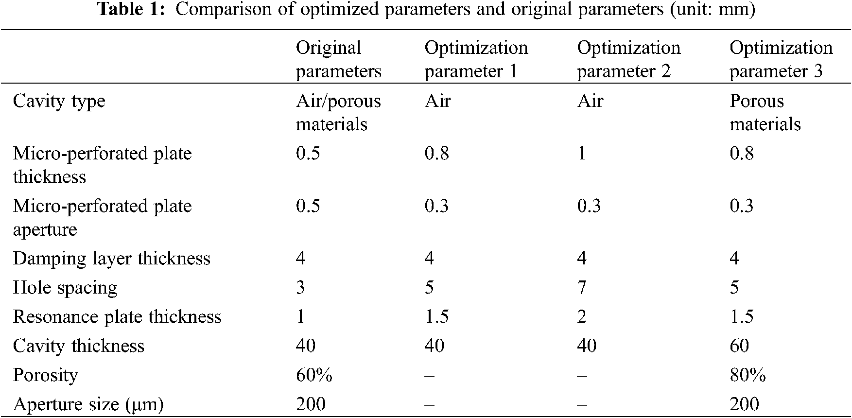
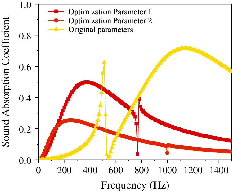
Figure 22: Comparison of the sound absorption coefficient of composite resonance plate of acoustic performance of optimized parameters with original parameters
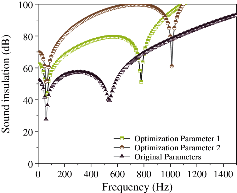
Figure 23: Comparison of the sound insulation capacity of composite resonance plate of acoustic performance of optimized parameters with original parameters
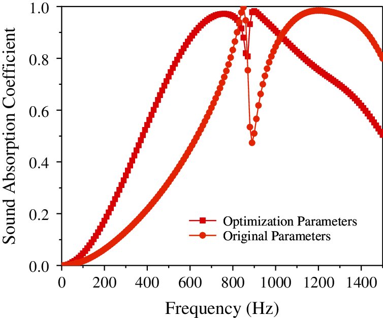
Figure 24: Comparison of the sound absorption coefficient of composite porous material resonance plate of acoustic performance of optimized parameters with original parameters
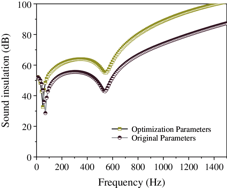
Figure 25: Comparison of the sound insulation of composite porous material resonance plate of acoustic performance of optimized parameters with original parameters
From Fig. 22, it is evident that after optimizing various parameters, the sound absorption coefficient of the composite resonance plate at low frequencies is significantly improved. Compared with that of optimized parameter 2, the sound absorption coefficient of optimized parameter 1 in the low frequency region is improved more significantly. Fig. 23 shows that after optimizing various parameters, the sound insulation of the composite resonant plate has a significant improvement at low frequencies. Among them, optimized parameter 2 has a more obvious improvement in the low-frequency region compared to that of optimized parameter 1. Fig. 24 illustrates that the parameters of the porous sound-absorbing material are optimized. After optimization, the sound absorption coefficient of the composite resonant plate has a significant increase in the low-frequency region, but there is a significant downward trend in the region from 800 Hz to 1000 Hz, where it reaches a trough and then rises again. Finally, Fig. 25 shows that after the parameter optimization of the porous sound-absorbing material, the sound insulation of the composite resonant plate has been significantly improved, and the improvement in the sound insulation at approximately 100 Hz is not obvious, but the sound insulation of the optimized composite resonance plate after 100 Hz is significantly improved compared to that of the original parameters. It shows that the optimization method in this study is not only effective for the cavity structure, but also effective for the composite resonance plate filled with porous materials.
This study investigates the sound absorption and sound insulation performance of a dual cavity resonant microporous plate, and analyzes the influence of structural factors on the sound absorption coefficient and sound insulation capacity. Additionally, the effect of porous ceramic foam on the acoustic performance after filling the structural cavity was studied. The study found that the aperture has the greatest impact on the sound absorption coefficient. The smaller the aperture, the greater the sound absorption coefficient. The thickness of the resonant plate has the greatest influence on the sound insulation and the resonant frequency. The greater the thickness, the wider the sound insulation frequency domain, and the greater the sound insulation. Moreover, the resonance frequency displays a trend toward higher values. After filling the cavity with porous ceramic foam, the porosity and thickness of the porous material have a more significant impact on the sound absorption coefficient, and the pore size has a small effect. Similarly, the effect of sound insulation is also more obvious when considering porosity and thickness. This study provides a theoretical basis and a method of guidance for future low-frequency noise reduction projects.
Acknowledgement: Thanks are due to Pengyu Du for assistance with the experiments and Wenbo Jia for valuable discussion.
Funding Statement: This study was supported by State Grid Corporation Science and Technology Project “Research on Comprehensive Control Technology of Low Frequency Noise of Distribution Transformers in Residential Areas” (5216A019000P).
Conflicts of Interest: The authors declare that they have no conflicts of interest to report regarding the present study.
1. Kim, H. S., Ma, P. S., Kim, B. K., Lee, S. H., Seo, Y. H. (2020). Sound transmission loss of multi-layered elastic micro-perforated plates in an impedance tube. Applied Acoustics, 166, 107348. [Google Scholar]
2. Kim, H. S., Ma, P. S., Kim, B. K., Kim, S. R., Lee, S. H. (2019). Low-frequency sound absorption of elastic micro-perforated plates in a parallel arrangement. Journal of Sound and Vibration, 460, 114884. [Google Scholar]
3. Zhou, H. A., Wang, X. M., Mei, Y. L. (2014). Theoretical analysis of the sound absorption characteristics of periodically stiffened micro-perforated plates. Acta Mechanica Sinica, 30(5), 714–726. [Google Scholar]
4. Kim, H. S., Kim, S. R., Kim, B. K., Ma, P. S., Seo, Y. H. (2020). Sound transmission loss of multi-layered infinite micro-perforated plates. Journal of the Acoustical Society of America, 147(1), 508–515. [Google Scholar]
5. Zhao, X. D., Yu, Y. J., Wu, Y. J. (2016). Improving low-frequency sound absorption of micro-perforated panel absorbers by using mechanical impedance plate combined with Helmholtz resonators. Applied Acoustics, 114, 92–98. [Google Scholar]
6. Bravo, T., Maury, C., Pinhède, C. (2012). Sound absorption and transmission through flexible micro-perforated panels backed by an air layer and a thin plate. Journal of the Acoustical Society of America, 131(5), 3853–3863. [Google Scholar]
7. Dah-You, M. (1997). General theory and design of microperforated-panel absorbers. Chinese Journal, 3, 3. [Google Scholar]
8. Dah-You, M. (1975). Theory and design of sound absorption structure of micro-perforated plate. Science China, 18(1), 40–52. [Google Scholar]
9. Kim, H. S., Ma, P. S., Kim, B. K., Kim, S. R., Lee, S. H. (2021). Near-field effects on the sound transmission and absorption of elastic micro-perforated plates in impedance tubes. Journal of Sound and Vibration, 499, 116001. [Google Scholar]
10. Hou, M., Wu, J., Yang, S., Wu, J. H., Ma, F. (2020). Expanding the strong absorption band by impedance matched mosquito-coil-like acoustic metamaterials. Review of Scientific Instruments, 91(2), 025102. [Google Scholar]
11. Xie, S., Wang, D., Feng, Z., Yang, S. (2020). Sound absorption performance of microperforated honeycomb metasurface panels with a combination of multiple orifice diameters. Applied Acoustics, 158, 107046. [Google Scholar]
12. Aurégan, Y., Farooqui, M. (2019). In-parallel resonators to increase the absorption of subwavelength acoustic absorbers in the mid-frequency range. Scientific Reports, 9(1), 1–6. [Google Scholar]
13. Yu, D., Wang, X., Mei, Y. (2020). A design method for Labyrinth sound absorption structure with micro-perforated plates. Journal of Physics: Conference Series, 1605(1), 012098. [Google Scholar]
14. Yang, J. W., Cai, J., Shao, C. (2013). Sound insulation property of the composite structure with micro-perforated panels and honeycomb core. Noise and Vibration Control, 4, 122–125. [Google Scholar]
15. Hu, S., Chen, S., Wu, X., Cai, J., Li, T. et al. (2019). Study of design and performance of composite resonance absorption barrier. Industrial Safety and Environmental Protection, 45(7), 77–80+96. [Google Scholar]
16. Liu, C. R., Wu, J. H., Yang, Z., Ma, F. (2020). Ultra-broadband acoustic absorption of a thin microperforated panel metamaterial with multi-order resonance. Composite Structures, 246, 112366. [Google Scholar]
17. Wang, C., Cheng, L., Pan, J., Yu, G. (2010). Sound absorption of a micro-perforated panel backed by an irregular-shaped cavity. Journal of the Acoustical Society of America, 127(1), 238–246. [Google Scholar]
18. Jung, J. D., Hong, S. Y., Song, J. H., Kwon, H. W. (2019). Sound insulation analysis of micro-perforated panel coupled with honeycomb panel considering air cavity for offshore plants. Proceedings of the Institution of Mechanical Engineers, Part M: Journal of Engineering for the Maritime Environment, 233(4), 1037–1055. [Google Scholar]
19. Li, L., Gang, X., Sun, Z., Zhang, X., Zhang, F. (2018). Design of phononic crystals plate and application in vehicle sound insulation. Advances in Engineering Software, 125, 19–26. [Google Scholar]
20. Zhang, D., Li, S., Shen, H., Men, X., Shang, W. (2009). Research and development of a micro-perforated panel structure. Mechanical Science and Technology for Aerospace Engineering, 28(11), 1526–1529. [Google Scholar]
21. Floss, S., Czwielong, F., Kaltenbacher, M., Becker, S. (2021). Design of an in-duct micro-perforated panel absorber for axial fan noise attenuation. Acta Acustica, 5, 24. [Google Scholar]
22. Hyun-Sil, K., Ma, P. S., Sang-Ryul, K., Seong-Hyun, L., Yun-Ho, S. (2018). A model for the sound absorption coefficient of multi-layered elastic micro-perforated plates. Journal of Sound and Vibration, 430, 75–92. [Google Scholar]
23. Sakagami, K., Morimoto, M., Yairi, M., Minemura, A. (2008). A pilot study on improving the absorptivity of a thick microperforated panel absorber. Applied Acoustics, 69(2), 179–182. [Google Scholar]
24. Bravo, T., Maury, C., Pinhède, C. (2013). Enhancing sound absorption and transmission through flexible multi-layer micro-perforated structures. Journal of the Acoustical Society of America, 134(5), 3663–3673. [Google Scholar]
25. Zhang, B., Li, L. L., Lu, W. J. (2010). Absorbing characteristics of the microperforated-panel on considering the effect of interaction between perforations. Applied Acoustics, 29(2), 134–140. [Google Scholar]
26. Li, Z., Wu, J., Zhao, G., Wang, K. (2017). Bidirectional sound absorption coefficient analysis and optimization of double layer micro-perforated plate structure. Audio Engineering, 41(Z4), 7–11. [Google Scholar]
27. Wang, H., Gao, Y., Yu, X. (2020). Sound absorption coefficient measurement based on three-dimensional sound intensity method. Journal of South China University of Technology (Natural Science), 48(7), 134. [Google Scholar]
 | This work is licensed under a Creative Commons Attribution 4.0 International License, which permits unrestricted use, distribution, and reproduction in any medium, provided the original work is properly cited. |