| Fluid Dynamics & Materials Processing |
DOI: 10.32604/fdmp.2022.018227
ARTICLE
A Critical Analysis of Natural Gas Liquefaction Technology
1Shengli College China University of Petroleum, Dongying, 257061, China
2Qingdao Nuocheng Chemical Safety Technology Co., Ltd., Qingdao, 266101, China
*Corresponding Author: Xiao Wu. Email: slxywuxiao@163.com
Received: 08 July 2021; Accepted: 06 August 2021
Abstract: Liquefied natural gas (LNG) is an important energy source and occupies an important proportion in natural gas consumption, therefore, the selection of appropriate liquefaction processes and related optimization should be seen as subjects of great importance. Accordingly, in the present review, we provide a comparative and critical analysis of the current status of natural gas liquefaction technology through examination of the advantages and disadvantages associated with three natural gas liquefaction processes (namely, the cascade liquefaction cycle, the expander-based cycle and the mixed refrigerant cycle). It is shown that the energy consumption related to the cascade refrigeration cycle is the lowest. Compared with it, the mixed refrigerant cycle has the advantages of being a simpler process, with less units, low investment cost and low requirements in terms of refrigerant purity. The expander-based cycle can be started and stopped quickly and simply, but the power consumption is relatively high.
Keywords: Natural gas; liquefaction; process; comparison; energy consumption
| Nomenclature | |
| A: | Auto consumption |
| HF: | Gross calorific value of feed gas after pretreatment |
| HL: | Gross calorific value of produced LNG |
| HN: | Gross calorific value of by-products |
| P: | Output of LNG |
| WS: | Specific power |
| WTOT: | Gas horse power |
| Abbreviation | |
| 3S: | Supersonic separator |
| DMR: | Double mixed refrigerant |
| LNG: | Liquefied natural gas |
| MRC: | Mixed-refrigerant cycle |
| NGL: | Natural gas liquid |
With the increase of the environment concerns all over the world, the role of natural gas in the future is becoming increasingly important. As show in Fig. 1, the prediction of future demand and supply of natural gas suggests that world needs for importing natural gas in the future [1,2]. Liquefied Natural Gas (LNG), which is mainly composed of methane, is recognized as the cleanest fossil energy on earth. LNG is colorless, tasteless, non-toxic and non-corrosive. And its volume is merely about 1/625 of the volume of gaseous natural gas and the mass is only about 45% of that of the water at the same volume [3]. The environmental protection advanced countries in the world are promoting the application of LNG. In addition to being used as fuel for power plants, factories and household users, the methane contained in LNG can be used as chemical raw materials for the manufacture of fertilizers, methanol solvents and acetic acid synthesis. Besides, the ethane and propane contained in LNG can be cleaved to produce ethylene and propylene, which is an important raw material for plastic products.
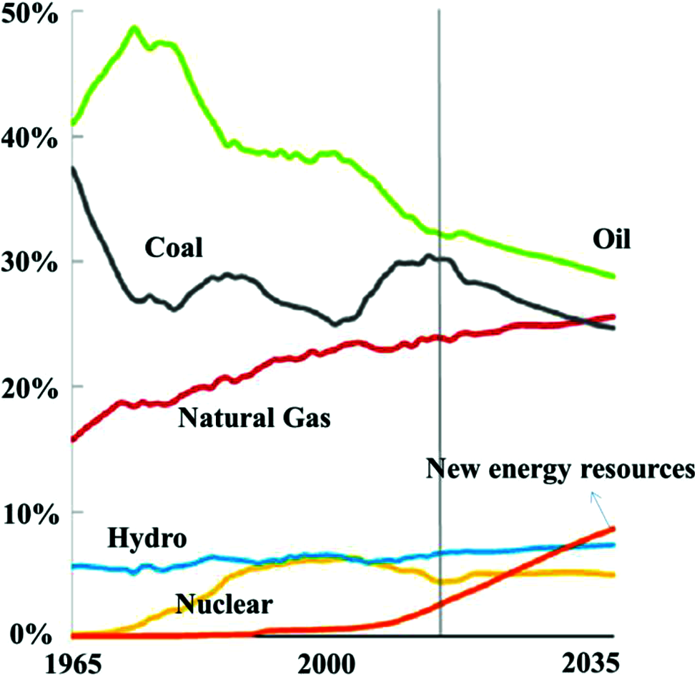
Figure 1: The prediction of different energy growth in the future by British Petroleum [1]
In recent years, with the rapid development of LNG industry in the world, the technology and equipment of liquefaction are also constantly developing and improving. Therefore, the study of liquefaction process of natural gas and equipment is of great significance to improve the efficiency of liquefaction plant and further promote its popularization and application. The technology of natural gas liquefaction comprises of pretreatment, gas-liquid separation, NGL (natural gas liquid) recovery, cryogenic process and heat exchange equipment [4,5], the schematic of the typical LNG plant is shown in Fig. 2. The essence of natural gas liquefaction is that natural gas in the heat exchanger can get enough cooling capacity, decreasing its temperature to 112 K under normal pressure, hence the liquefaction process is the core content of natural gas liquefaction. In order to reduce the investment and operation cost of natural gas liquefaction plant and improve the production capacity of LNG, an appropriate liquefaction process should be adopted. According to the different refrigeration methods, the process of natural gas liquefaction can be divided into cascade liquefaction cycle [6], expander-based cycle [7] and mixed refrigerant cycle [8].
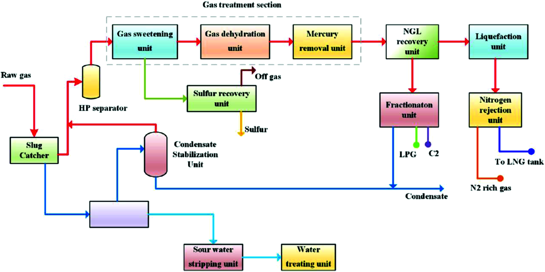
Figure 2: The schematic of the typical LNG plant [4]
The working principle of cascading liquefaction process is that a separate refrigeration cycle composed of pure refrigerant is used to provide cooling capacity for natural gas at different temperature stages [9]. The flow chart of cascade liquefaction cycle is shown in Fig. 3.
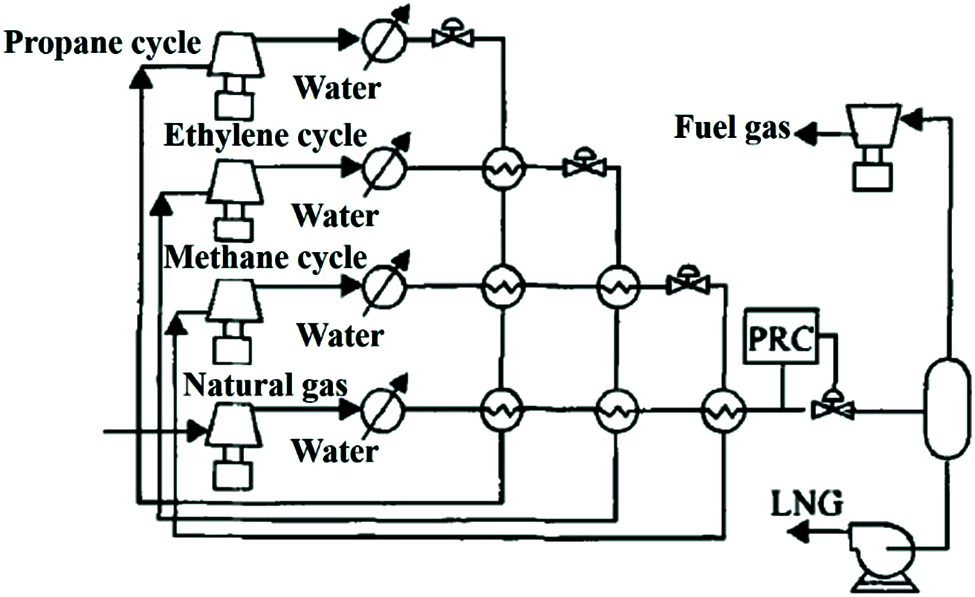
Figure 3: The cascade liquefaction flow chart
As can be seen from Fig. 3, in the tertiary refrigeration cycle, the tertiary heat transfer is adopted in each refrigeration cycle to gradually precool the refrigerants of other refrigeration cycles and gradually cool the feed natural gas. For instance, the primary propane refrigeration cycle can cool natural gas, ethylene and methane to about −35°C. The secondary ethylene refrigeration cycle can cool natural gas and methane to −85°C. The tertiary methane refrigeration cycle can cool natural gas to −160°C [10]. In the natural gas liquefaction process, natural gas is heat exchanged step by step in nine LNG heat exchangers respectively, thereby making the natural temperature-enthalpy curve closer to the temperature-enthalpy curve of refrigerant. Finally, the pressure of natural gas is reduced to the normal pressure state through throttling effect [11].
In the actual production, the compression stages should be carefully selected for the liquefaction process because it has a great influence on equipment investment and energy consumption. More stages used will increase the number of compressors and other equipment, which makes the initial investment increase. Yet the operation cost is decreased with the reduction of energy consumption, which is suitable for factories with large production scales; More stages used will make the equipment investment low and energy consumption more, which is suitable for small-scale factories [12].
The advantages of the cascade liquefaction cycle are: (1) The energy consumption is low and the refrigerant consumed by the production of unit LNG can be minimized with a reasonably-designed cascade process; (2) All refrigerants are pure components; (3) The technology is mature and the operation is stable. The disadvantages are: (1) The process is more complicated because there are more equipments; (2) There are more circulating pipes in the process, which increases the difficulty of control and maintenance.
The expander-based cycle means that the temperature drop is generated to provide cooling capacity through the adiabatic expansion of high-pressure refrigerant or feed gas in the expander [13]. The two major characteristics of the process are: (1) The turbo expander can provide cooling capacity and meanwhile output shaft power, which can provide power to the compressor equipment in the process; (2) When a certain pressure difference between the feed natural gas and commercial gas is satisfied, there is no need to input external energy into the liquefaction process.
3.1 Natural Gas Expansion Liquefaction Process
Fig. 4 presents the schematic diagram of the natural gas expansion-based liquefaction process [14]. In this process, the natural gas transported from the gas pipeline network is used as feed gas and simultaneously used for refrigeration. The high-pressure natural gas undergoes adiabatic expansion in the expander to induce a temperature drop, which is used to cool another part of the natural gas. As presented in Fig. 4, it is called an open cycle because low-pressure natural gas is transported to the urban gas distribution network as commercial gas. If the low-pressure natural gas is pressurized to the pressure of the pipe network and re-enters the liquefaction process, it is called a closed cycle.
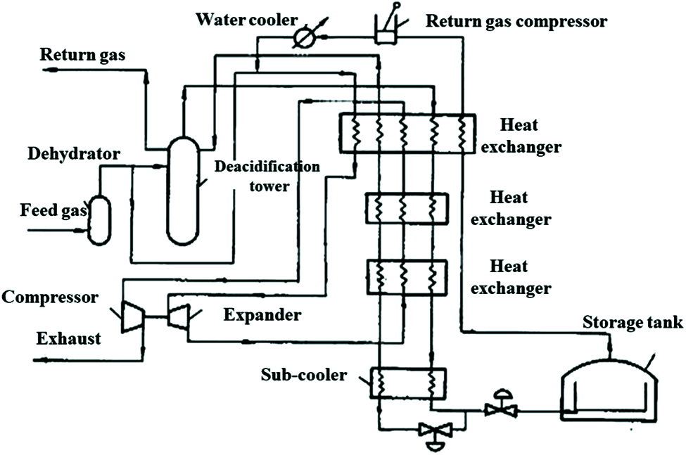
Figure 4: The expansion liquefaction process
The advantages of this process are: (1) The pressure of the feed gas can be used as the power to provide cooling capacity, reducing the power consumption of the cycle; (2) No pretreatment is required because the part of the feed gas is used as a refrigerant. The disadvantages are: (1) Due to the limitation of natural gas pressure, the temperature obtained in the expansion is not low enough, resulting in lower LNG production and more flash steam in the storage tank; (2) In order to obtain a cooling capacity of lower temperature, the pressure difference before and after the expander needs to be increased, hence a compressor needs to be installed to increase the pressure of the natural gas, which increases the power consumption; (3) The composition and pressure fluctuations of the feed natural gas have a great impact on the working performance of the expander, thus the operating flexibility and safety of the system are poor.
3.2 Nitrogen Expansion Liquefaction Process
Fig. 5 presents the nitrogen expansion liquefaction process [15]. The nitrogen extracted from the feed gas is used as the refrigerant in this process. And the natural gas liquefaction process and the nitrogen refrigeration cycle are independent of each other.
In the nitrogen refrigeration cycle, after the high-pressure nitrogen is pre-cooled by the heat exchanger 2, it is cooled by two expanders respectively and used as the refrigerant of the heat exchangers 2, 4, and 5. The nitrogen separated from the nitrogen-methane separation tower 8 is mixed with the reverse flow refrigerant in the heat exchanger 5 to provide the refrigerant raw material in the refrigerant cycle. In the natural gas liquefaction process, the feed gas experiences pretreatment, pre-cooling, heavy hydrocarbon separation, liquefaction, nitrogen separation, and sub-cooling to obtain LNG products.
Compared with the mixed refrigerant liquefaction process, the advantages of the nitrogen expansion liquefaction process are: (1) The process is simple and the cost is low; (2) The start-up is fast and the operation flexibility is high and flexible; (3) Due to the non-flammability of nitrogen, the safety is high. The disadvantage is that the power consumption of compressor is high [16].
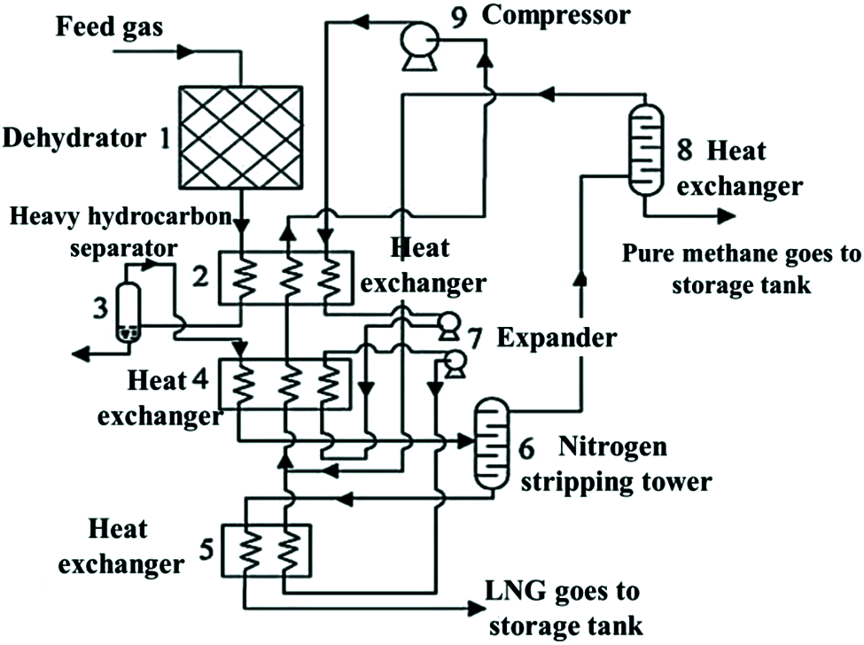
Figure 5: The nitrogen expansion liquefaction process
3.3 Nitrogen-Methane Expansion Liquefaction Process
Fig. 6 shows the schematic diagram of a typical nitrogen-methane expansion liquefaction process. The difference is that a mixture of nitrogen and methane is adopted as refrigerant, which makes the temperature-enthalpy curve of the refrigerant not a horizontal line. And the temperature difference between the hot and cold composite curves in the heat exchanger is reduced, which can decrease the power consumption by 10%–20% [17].
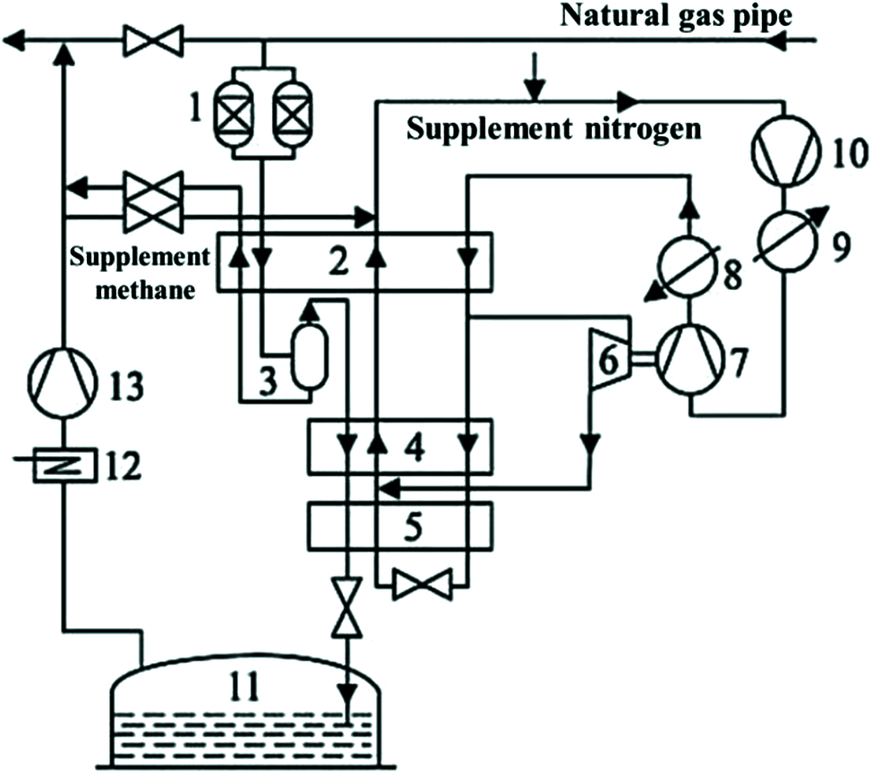
Figure 6: The nitrogen-methane expansion liquefaction process (1-Pretreatment device; 2, 4 and 5-Heat exchanger; 3-Gas-liquid separator; 6-Turbo-expander; 7-Brake compression; 8 and 9-Water cooler; 10-Circulating compressor; 11-Storage tank; 12-Preheater; 13-Compressor)
The characteristics of the mixed-refrigerant cycle (MRC) is that a multi-element mixture composed of C1 (methane) to C5 (pentane) hydrocarbons and nitrogen is adopted as the refrigerant. And the refrigeration method is throttling refrigeration [18,19].
The major feature of MRC is that the boiling point of each component in the refrigerant is different, hence it can be condensed and evaporated step by step in different heat exchangers to provide cooling capacity at different temperature stages, which cools the natural gas to liquefy. Even in the same heat exchanger, as the composition of the refrigerant constantly changes while providing cooling capacity, its cooling temperature accordingly changes constantly, making the cold-heat composite curve in the heat exchanger closer and reducing the exergy loss in the heat exchange process. In the cascade refrigeration cycle, the evaporation temperature of the refrigerant composed of pure components remains unchanged in the heat exchanger or is reduced due to the pressure drop. MRC can be viewed as a cascade refrigeration cycle with infinite stages and has become the most dynamic liquefaction process since the 1970s because it combines the advantages of cascade refrigeration cycles and overcomes the disadvantages of more refrigeration cycles.
Compared to the cascade liquefaction cycle, the advantages of MRC are: (1) The number of compressors and other equipment is reduced with the fewer refrigeration cycles, which can save the equipment investment by 15%–20%; (2) The management is convenient. The disadvantages of MRC are: (1) The energy consumption of MRC process will increase by 10%–20% because the energy consumption of single-stage compression is higher than that of multi-stage compression. (2) The ratio of mixed refrigerants has a large energy consumption for the process, yet it is difficult to obtain the optimal ratio. (3) It is necessary to perform accurate phase equilibrium calculations for each node in the process when thermodynamic analysis of the process is performed and the calculation is more difficult.
4.1 Mixed-Refrigerant Cycle without Pre-Cooling
According to whether the natural gas liquefaction process and the mixed refrigerant cycle are independent, the mixed-refrigerant cycle without pre-cooling can be divided into closed MRC process and open MRC process [20].
The closed MRC process refers to the process in which the natural gas liquefaction loop and the mixed refrigerant refrigeration cycle form an independent system respectively [21]. Fig. 7 presents the schematic diagram of the process.
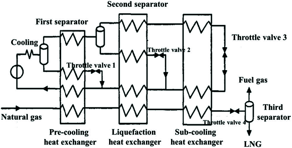
Figure 7: The closed mixed-refrigerant cycle
In the refrigeration cycle, the gaseous mixed refrigerant is pressurized by the compressor to about 0.4 MPa. After being cooled by the water, air or cold cycle, the heavy components in the refrigerant will condense out and then experience gas-liquid separation. In the subsequent process, the liquid phase enters the heat exchanger for sub-cooling and it is mixed with the reverse flow refrigerant to become the refrigerant of the heat exchanger of this stage after the throttling temperature drops. The gas phase becomes the gas-liquid two phase for separation after receiving the cooling energy to provide refrigerant for subsequent heat exchangers.
In the liquefaction loop of natural gas, the natural gas is pre-cooled, condensed and sub-cooled through three LNG heat exchangers, finally reducing to storage pressure after the throttle valve 4. Generally, the liquefaction rate of natural gas cannot reach 100%, hence LNG needs to pass through the third separator for gas-liquid separation. The liquid phase is stored as a LNG product in a cryogenic and normal-pressure storage tank. And the gas phase can be used as commercial gas or fuel gas after the cooling capacity is recovered.
Fig. 8 shows the diagram of the open MRC process. As can be presented, the natural gas simultaneously plays the two roles of refrigerant and feed gas, which is similar to the closed cycle in nitrogen expansion refrigeration. There is no need to consider the ratio of the refrigerant because the ratio of the mixed refrigerant is the same as that of the feed gas [22,23].
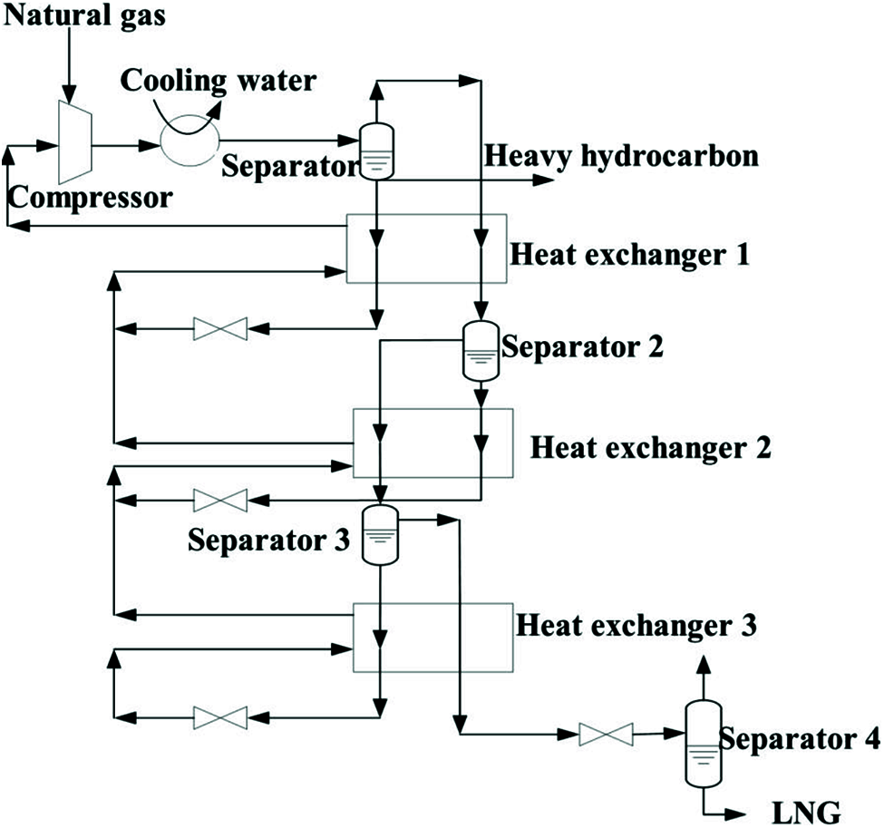
Figure 8: The open mixed-refrigerant cycle
The feed natural gas and low-pressure natural gas used as a refrigerant are simultaneously compressed by the compressor and enter the two-phase separator after cooling. Part of the heavy hydrocarbon is separated. The gas phase is transformed into a gas-liquid two-phase again after receiving the cooling capacity and then the two-phase separation is carried out to provide the refrigerant for the subsequent process. In the whole process, the low-pressure liquid phase is used as the refrigerant and the gas phase is gradually cooled, finally becoming LNG.
4.2 Mixed-Refrigerant Cycle with Pre-Cooling
The MRC with pre-cooling fully absorbs the advantages of the cascade cycle and reduces the total power consumption by adding the pre-cooling link. Both APCI and Shell of the United States can adjust the amount of liquid refrigerant by controlling the temperature of the mixed refrigerant after pre-cooling, which greatly increases operation flexibility and boosts cooling efficiency [24–26].
4.2.1 Propane Mixed-Refrigerant Cycle (C3/MRC)
The refrigerant used in the pre-cooling cycle of the C3/MRC is propane and the final pre-cooling temperature can reach about −35°C, which shortens the temperature range of the mixed refrigerant cycle, as shown in Fig. 9. Therefore, the power consumption of the C3/MRC is lower than that of the MRC. Because the C3/MRC combines the advantages of MRC and cascade refrigeration cycle, it is currently the most dynamic liquefaction process in the world. Both the APCI and Shell of the United States have their own patents in this process [27,28].
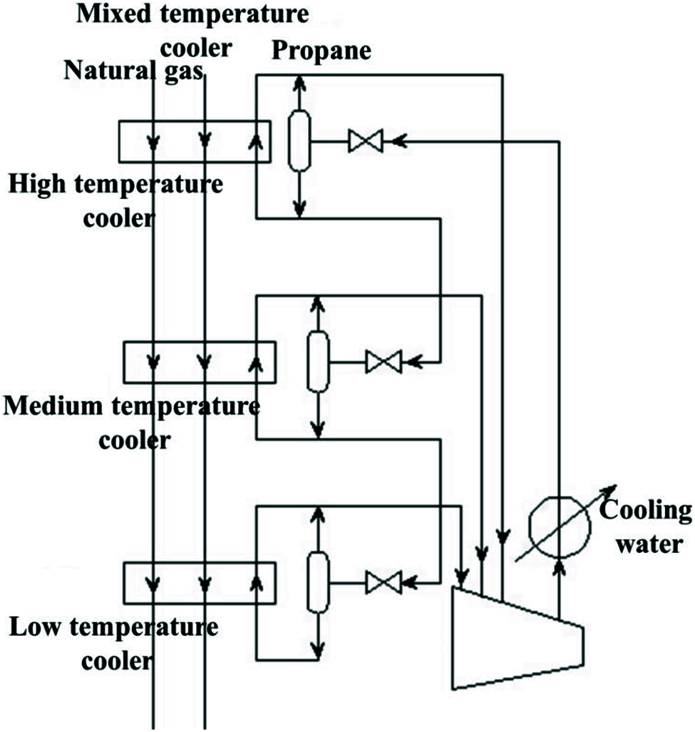
Figure 9: The propane mixed-refrigerant cycle
In the propane pre-cooling cycle, triple-stage heat exchange is employed to reduce power consumption. Because the propane is a pure refrigerant, its evaporation temperature remains unchanged when the pressure drop of the heat exchanger is not considered. Thus, the more heat exchangers are used, the more heat transfer losses and power consumption are decreased. The cooling capacity provided by each refrigerator is controlled by the amount of liquid propane. And the liquid propane is all vaporized in the refrigerator to provide maximum cooling capacity.
The difference is that the refrigeration temperature range of the C3/MRC is from −35°C to −160°C, hence the mixed-refrigerant only needs four components, thereby reducing the molecular weight of the refrigerant and enhancing the efficiency of the compressor.
4.2.2 Double Mixed Refrigerant (DMR)
Fig. 10 presents the schematic diagram of the DMR cycle. The DMR cycle is an improvement of the C3/MRC. The natural gas and the mixed refrigerant can be cooled to about −60°C to −80°C after the refrigerant of pre-cooling cycle is changed to a mixture [29]. In the DMR cycle, as the composition of the cold and hot streams in the pre-cooling heat exchanger is similar, the temperature-enthalpy curves of the cold and hot composite curves are closer, thereby reducing energy loss.
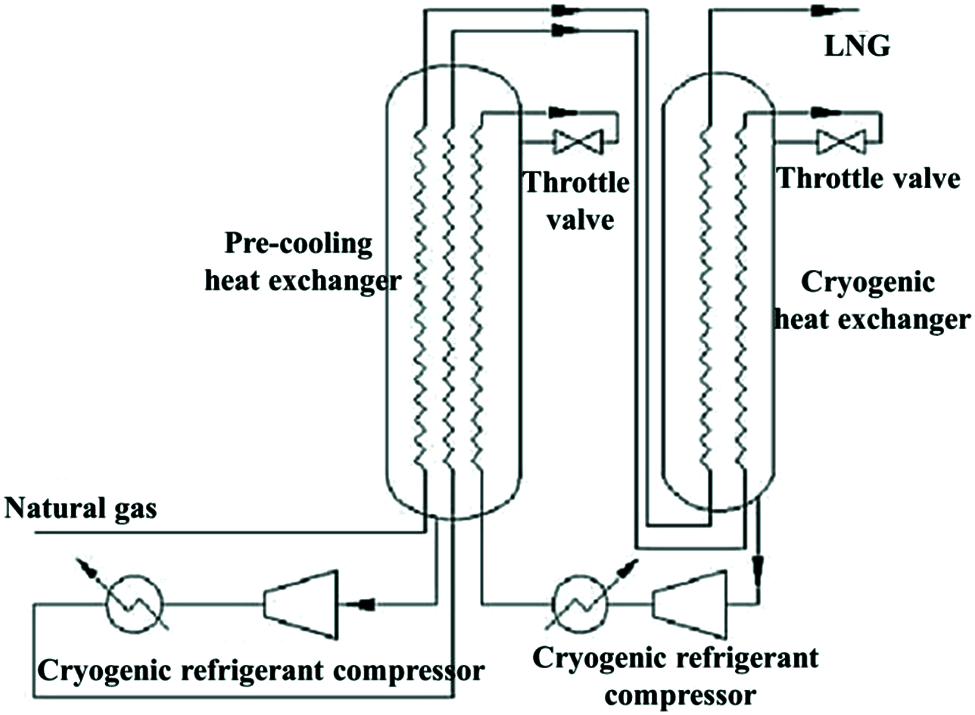
Figure 10: The double mixed-refrigerant cycle
4.3 New Technology of Natural Gas Liquefaction and Pre-Cooling
The supersonic separator (3S technology) technology is an emerging natural gas liquefaction technology in recent years. In comparison to traditional technology of natural gas liquefaction, it has the advantages of compact and lighter structure, convenient operation, supporting unmanned operation (suitable for subsea natural gas processing), little dependence on hydrate inhibitors and low costs of investment and operating [30]. The basic principle of natural gas liquefaction or pre-cooling through the Laval nozzle is to use the expansion and refrigeration effect of the nozzle to achieve the temperature of natural gas liquefaction, or to achieve the purpose of decreasing the temperature of natural gas [31].
At present, this technology has been successfully applied in the field of natural gas dehydration and heavy hydrocarbon removal [32]. In recent years, relevant scholars have proposed to apply this technology to the field of natural gas liquefaction [33]. The supersonic liquefaction process is simple, less equipment, easy to maintain, and no additional energy is needed [34,35].
5 Analysis and Comparison of Natural Gas Liquefaction Cycle
Specific power (WS) is a key index to measure the thermodynamic efficiency of liquefaction process, which is defined as:
The composition of feed gas, the type and design of liquefaction equipment, the selection of refrigerant and refrigeration cycle, the temperature of cooling medium, the approach temperature of cold and hot medium in heat exchanger, and the compressor efficiency will affect the specific power.
Auto consumption (A) is another index to measure the efficiency of liquefaction process, which is defined as:
Table 1 presents the comparison of energy consumption among three common liquefaction cycles and their improved processes under the production of unit LNG. The specific power consumption of classical cascade liquefaction cycle is minimum (0.33 kwh/kg), which is set as the comparison value 1 [36–38]. The specific power consumption of the expander-based cycle is the largest because the expansion working fluid is a low-density gas, which produces a very low temperature drop. In order to make natural gas decrease to the required temperature, it is necessary to increase the refrigerant flow rate and the pressure ratio of compressor, thereby making it the largest energy consumption in all cycles. The specific power consumption of the MRC or the expander-based cycler decreases with the increase of the stages, which is the result of reducing the pressure ratio of compressor.
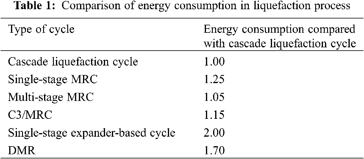
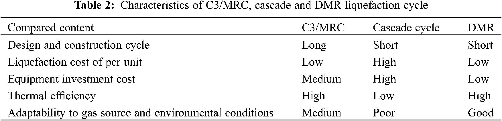
Table 2 shows the comparison of characteristics of DMR, C3/MRC and cascade liquefaction cycle provided by Shell. As can be presented, the cascade liquefaction cycle has the advantage in the design and construction cycle and has the disadvantage in terms of liquefaction cost of unit LNG, equipment investment cost, thermal efficiency and adaptability. The DMR is similar to the C3/MRC in terms of liquefaction cost of per unit LNG and is superior to the C3/MRC in the rest of performances. It can be seen that the cascade liquefaction cycle is gradually being eliminated. And the C3/MRC and the DMR are widely used in large-scale LNG plants due to their low operation cost and high efficiency. In the next step, each liquefaction cycle can be further optimized in combination with optimization algorithms. the objective functions considered include total energy consumption, specific energy consumption, capital costs, operation costs, etc. [39–41].
In this paper, based on the research status of natural gas liquefaction refrigeration cycle, the advantages and defects of three widely-used natural gas liquefaction refrigeration cycle, including the cascade liquefaction cycle, expander-based cycle and mixed-refrigerant cycle, are emphasized. And the optimization of the process is achieved through comparative analysis.
The cascade liquefaction cycle has the advantage in the design and construction cycle and has the disadvantage in terms of unit LNG liquefaction cost, equipment investment cost, thermal efficiency and adaptability. The DMR is similar to the C3/MRC process in terms of unit liquefaction cost and is superior to the C3/MRC process in the rest of performances. The cascade liquefaction cycle is gradually being eliminated and the C3/MRC and the DMR are widely used in large-scale LNG plants due to their low operation cost and high efficiency.
As for the large-scale LNG plants built in tropical regions, it is reasonable to adopt the C3/MRC. And MRC can be used for other cases. The nitrogen expansion liquefaction with pre-cooling cycle is not the most economical option for large-scale plants built on land. Yet it is more suitable for small-scale natural gas plant in remote areas and offshore processing plant due to its simple process, small number of equipment, easy access to refrigerants and replenishment.
In the next step of the study, in order to achieve the purpose of improving the liquefaction equipment and further promoting its popularization and application, each liquefaction cycle can be further optimized in combination with optimization algorithms.
Funding Statement: This work was supported by the Science Development Funding Program of Dongying of China (Grant No. DJ2020009).
Conflicts of Interest: The authors declare that they have no conflicts of interest to report regarding the present study.
1. Dudley, B. (2016). BP energy outlook 2035. London, UK: British Petroleum. [Google Scholar]
2. Li, M., Sun, J., Liu, D., Li, Y., Hu, J. (2020). A model for the optimization of the shale gas horizontalwell section based on the combination of different weighting methods in the frame of the game theory. Fluid Dynamics & Materials Processing, 16(5), 993–1005. DOI 10.32604/fdmp.2020.010443. [Google Scholar] [CrossRef]
3. Lin, W., Na, Z., Gu, A. (2010). LNG (liquefied natural gasA necessary part in china’s future energy infrastructure. Energy, 35(11), 4383–4391. DOI 10.1016/j.energy.2009.04.036. [Google Scholar] [CrossRef]
4. Al-Ajmi, R., Mosaad, M. (2011). Heat exchange between film condensation and porous: Natural convection across a verticalwall. Fluid Dynamics & Materials Processing, 8(1), 51–68. DOI 10.3970/fdmp.2011.008.051. [Google Scholar] [CrossRef]
5. Merouani, L., Zeghmati, B., Belhamri, A. (2013). Convective film condensation in an inclined channel with porous layer. Fluid Dynamics & Materials Processing, 9(3), 267–290. DOI 10.3970/fdmp.2013.009.267. [Google Scholar] [CrossRef]
6. Gomez, J. R., Gomez, M. R., Bernal, J. L., Insua, A. B. (2015). Analysis and efficiency enhancement of a boil-off gas reliquefaction system with cascade cycle on board LNG carriers. Energy Conversion & Management, 94(3), 261–274. DOI 10.1016/j.enconman.2015.01.074. [Google Scholar] [CrossRef]
7. Li, J., Li, P., Gao, G., Pei, G., Su, Y. et al. (2017). Thermodynamic and economic investigation of a screw expander-based direct steam generation solar cascade rankine cycle system using water as thermal storage fluid. Applied Energy, 195(7), 137–151. DOI 10.1016/j.apenergy.2017.03.033. [Google Scholar] [CrossRef]
8. Wang, Z., Han, F., Ji, Y., Li, W. (2020). Analysis on feasibility of a novel cryogenic heat exchange network with liquid nitrogen regeneration process for onboard liquefied natural gas reliquefaction. Case Studies in Thermal Engineering, 22, 100760. DOI 10.1016/j.csite.2020.100760. [Google Scholar] [CrossRef]
9. Pozo, C., Lvaro, N. J., Martín, J. R., Paniagua, I. L. (2021). Efficiency evaluation of closed and open cycle pure refrigerant cascade natural gas liquefaction process through exergy analysis. Journal of Natural Gas Science and Engineering, 89(1), 103868. DOI 10.1016/j.jngse.2021.103868. [Google Scholar] [CrossRef]
10. Majeed, K., Qyyum, M. A., Nawaz, A., Ahmad, A., Lee, M. (2020). Shuffled complex evolution-based performance enhancement and analysis of cascade liquefaction process for large-scale LNG production. Energies, 13(10), 2511. DOI 10.3390/en13102511. [Google Scholar] [CrossRef]
11. Boyaghchi, F. A., Sohbatloo, A. (2018). Assessment and optimization of a novel solar driven natural gas liquefaction based on cascade orc integrated with linear fresnel collectors. Energy Conversion & Management, 162(47), 77–89. DOI 10.1016/j.enconman.2018.02.013. [Google Scholar] [CrossRef]
12. Wang, Q. (2011). Study on the adiabatic mixing effects in an auto-cascade natural gas liquefaction cycle with a rectifier. Journal of Engineering Thermophysics, 32(4), 549–552. DOI 10.1007/s12182-011-0123-3. [Google Scholar] [CrossRef]
13. Zhang, J., Meerman, H., Benders, R., Faaij, A. (2020). Technical and economic optimization of expander-based small-scale natural gas liquefaction processes with absorption precooling cycle. Energy, 191(1–2), 116592. DOI 10.1016/j.energy.2019.116592. [Google Scholar] [CrossRef]
14. Du, H. P., Cui, J. S., Ji, Z. M., Li, H. Y., Jia, L. X. (2011). Refrigeration process and optimization of BOG recovery in LNG filling station. Advanced Materials Research, 172, 235–239. DOI 10.4028/www.scientific.net/AMR.171-172.235. [Google Scholar] [CrossRef]
15. He, T., Ju, Y. (2014). A novel conceptual design of parallel nitrogen expansion liquefaction process for small-scale LNG (liquefied natural gas) plant in skid-mount packages. Energy, 75(10), 349–359. DOI 10.1016/j.energy.2014.07.084. [Google Scholar] [CrossRef]
16. Gao, T., Lin, W., Wei, L., Gu, A., Qi, Y. (2011). CBM liquefaction process integrated with distillation separation of nitrogen. Journal of Chemical Engineering of Japan, 44(8), 555–560. DOI 10.1252/jcej.10we032. [Google Scholar] [CrossRef]
17. Gao, T., Lin, W., Gu, A., Min, G. (2010). Coalbed methane liquefaction adopting a nitrogen expansion process with propane pre-cooling. Applied Energy, 87(7), 2142–2147. DOI 10.1016/j.apenergy.2009.12.010. [Google Scholar] [CrossRef]
18. Tak, K., Lee, I., Kwon, H., Kim, J., Ko, D. et al. (2015). Comparison of multistage compression configurations for single mixed refrigerant processes. Industrial and Engineering Chemistry Research, 54(41), 9992–10000. DOI 10.1021/acs.iecr.5b00936. [Google Scholar] [CrossRef]
19. Kai, L. (2010). Experiment and composition analysis of pre-cooling mixed refrigerant cycle gas liquefaction system. Cryogenics, 25(4), 37–41. DOI 10.1109/CCECE.2010.5575154. [Google Scholar] [CrossRef]
20. Lee, C., Jin, L., Park, C., Jeong, S. (2016). Design of non-flammable mixed refrigerant joule-thomson refrigerator for precooling stage of high temperature superconducting power cable. Cryogenics, 81(1), 14–23. DOI 10.1016/j.cryogenics.2016.11.003. [Google Scholar] [CrossRef]
21. Ghorbani, B., Shirmohammadi, R., Mehrpooya, M. (2018). A novel energy efficient lNG/NGL recovery process using absorption and mixed refrigerant refrigeration cycles–economic and exergy analyses. Applied Thermal Engineering, 132, 283–295. DOI 10.1016/j.applthermaleng.2017.12.099. [Google Scholar] [CrossRef]
22. Nogal, F. D., Kim, J. K., Perry, S., Smith, R. (2008). Optimal design of mixed refrigerant cycles. Industrial & Engineering Chemistry Research, 47(22), 8724–8740. DOI 10.1021/ie800515u. [Google Scholar] [CrossRef]
23. Kuz’Menko, I. F., Dovbish, A. L., Darbinyan, R. V., Peredel’Skii, V. A., Lyapin, A. I. (2003). Efficient natural gas liquefaction plant based on AGFCS by using open klimenko cycle. Chemical & Petroleum Engineering, 39(3), 216–220. DOI 10.1023/A:1024294601975. [Google Scholar] [CrossRef]
24. Shen, D., Gui, C., Xia, J., Xue, S. (2020). Experimental analysis of the performances of unit refrigeration systems based on parallel compressors with consideration of the volumetric and isentropic efficiency. Fluid Dynamics & Materials Processing, 16(3), 489–500. DOI 10.32604/fdmp.2020.08969. [Google Scholar] [CrossRef]
25. Hu, C. X., Shi, Y., Li, G. L. (2012). System design and experiments study on 120 K the segregation linder refrigerator with pre-cooling cycle. Applied Mechanics & Materials, 170, 2629–2633. DOI 10.4028/www.scientific.net/AMM.170-173.2629. [Google Scholar] [CrossRef]
26. Yoon, J. I., Choi, K. H., Lee, H. S., Kim, H. J., Son, C. H. (2015). Assessment of the performance of a natural gas liquefaction cycle using natural refrigerants. Heat and Mass Transfer, 51(1), 95–105. DOI 10.1007/s00231-014-1399-9. [Google Scholar] [CrossRef]
27. Alabdulkarem, M., Hwang, Y. H., Radermacher, R. (2011). Optimization of propane pre-cooled mixed refrigerant LNG plant. Applied Thermal Engineering, 31(6), 1091–1098. DOI 10.1016/j.applthermaleng.2010.12.003. [Google Scholar] [CrossRef]
28. Fahmy, M., Nabih, H. I., El-Aziz, M. R. A. (2016). Investigation and performance improvement of the propane precooling cycle in the propane precooled mixed refrigerant cycle liquefaction process. Industrial & Engineering Chemistry Research, 55(10), 2769–2783. DOI 10.1021/acs.iecr.5b04249. [Google Scholar] [CrossRef]
29. Nibbelke, R., Kauffman, S., Pek, B. (2002). Double mixed refrigerant LNG process provides viable alternative for tropical conditions. Oil and Gas Journal, 100(27), 64–66. [Google Scholar]
30. Cao, X. W., Liu, Y., Zang, X. R., Guo, D., Bian, J. (2021). Supersonic refrigeration performances of nozzles and phase transition characteristics of wet natural gas considering shock wave effects. Case Studies in Thermal Engineering, 24, 100833. DOI 10.1016/j.csite.2020.100833. [Google Scholar] [CrossRef]
31. Bian, J., Cao, X. W., Yang, W., Song, X. D., Xiang, C. C. et al. (2019). Condensation characteristics of natural gas in the supersonic liquefaction process. Energy, 168, 99–110. DOI 10.1016/j.energy.2018.11.102. [Google Scholar] [CrossRef]
32. Cao, X., Bian, J. (2019). Supersonic separation technology for natural gas processing: A review. Chemical Engineering and Processing-Process Intensification, 136, 138–151. DOI 10.1016/j.cep.2019.01.007. [Google Scholar] [CrossRef]
33. Bian, J., Cao, X. W., Yang, W., Edem, M. A., Yin, P. B. et al. (2018). Supersonic liquefaction properties of natural gas in the laval nozzle. Energy, 159, 706–715. DOI 10.1016/j.energy.2018.06.196. [Google Scholar] [CrossRef]
34. Bian, J., Cao, X. W., Yang, W., Guo, D., Xiang, C. C. (2020). Prediction of supersonic condensation process of methane gas considering real gas effects. Applied Thermal Engineering, 164, 114508. DOI 10.1016/j.applthermaleng.2019.114508. [Google Scholar] [CrossRef]
35. Cao, X. W., Guo, D., Sun, W. J., Zhang, P., Ding, G. Y. et al. (2021). Supersonic separation technology for carbon dioxide and hydrogen sulfide removal from natural gas. Journal of Cleaner Production, 288, 125689. DOI 10.1016/j.jclepro.2020.125689. [Google Scholar] [CrossRef]
36. Wang, M., Jian, Z., Qiang, X. (2012). Optimal design and operation of a C3MR refrigeration system for natural gas liquefaction. Computers & Chemical Engineering, 39(6), 84–95. DOI 10.1016/j.compchemeng.2011.12.003. [Google Scholar] [CrossRef]
37. Qyyum, M. A., Qadeer, K., Lee, S., Lee, M. (2018). Innovative propane-nitrogen two-phase expander refrigeration cycle for energy-efficient and low-global warming potential LNG production. Applied Thermal Engineering, 139, 157–165. DOI 10.1016/j.applthermaleng.2018.04.105. [Google Scholar] [CrossRef]
38. Khan, M. S., Lee, M. (2013). Design optimization of single mixed refrigerant natural gas liquefaction process using the particle swarm paradigm with nonlinear constraints. Energy, 49(12), 146–155. DOI 10.1016/j.energy.2012.11.028. [Google Scholar] [CrossRef]
39. Al-Sobhi, S. A., Elkamel, A. (2015). Simulation and optimization of natural gas processing and production network consisting of LNG, GTL, and methanol facilities. Journal of Natural Gas Science & Engineering, 23, 500–508. DOI 10.1016/j.jngse.2015.02.023. [Google Scholar] [CrossRef]
40. Sun, H., Shu, D., Zhu, H. M. (2012). Process optimization of one-stage propane pre-cooled MRC cycle for small-scale LNG plant. Advanced Materials Research, 516, 1184–1187. DOI 10.4028/www.scientific.net/AMR.516-517.1184. [Google Scholar] [CrossRef]
41. Tak, K., Lim, W., Choi, K., Ko, D., Moon, I. (2011). Optimization of mixed-refrigerant system in LNG liquefaction process. Computer Aided Chemical Engineering, 29(22), 1824–1828. DOI 10.1016/B978-0-444-54298-4.50143-4. [Google Scholar] [CrossRef]
 | This work is licensed under a Creative Commons Attribution 4.0 International License, which permits unrestricted use, distribution, and reproduction in any medium, provided the original work is properly cited. |