| Fluid Dynamics & Materials Processing |
DOI: 10.32604/fdmp.2022.017566
ARTICLE
Influence of the Impeller/Guide Vane Clearance Ratio on the Performances of a Nuclear Reactor Coolant Pump
1Lanzhou University of Technology, College of Energy and Power Engineering, Lanzhou, 730050, China
2Key Laboratory of Fluid Machinery and Systems of Gansu Province, Lanzhou, 730050, China
*Corresponding Author: Xiaorui Cheng. Email: cxr168861@sina.com
Received: 20 May 2021; Accepted: 24 August 2021
Abstract: An AP1000 nuclear reactor coolant pump is considered to assess the influence of the Impeller/Guide vane clearance on the performances of this type of pumps. Experiments and numerical simulations relying on an unidirectional fluid-solid coupling approach are used to investigate the problem (stress, strain and mode of the rotor). The results reveal the relationship existing between the hydraulic performance of the nuclear reactor coolant pump and the clearance ratio. The effect of clearance ratio on the maximum equivalent stress on the back surface of the impeller blade is greater than that on the working surface (the maximum equivalent stress on the back surface of impeller blade is about three times that on the working surface). The clearance ratio has a scarce effect on the first six natural frequencies of the rotor of the nuclear reactor coolant pump. The related vibrational modes have different waveforms.
Keywords: Nuclear reactor coolant pump; clearance ratio; fluid-solid coupling; stress and strain; numerical calculation
The nuclear reactor coolant pump is the core component of the nuclear island in the nuclear power plant, whose (and its) stability directly affect the power generating capacity and safety of the atomic power plant. The dynamic-static coupling mode between guide vane and impeller of the third-generation nuclear reactor coolant pump makes the clearance ratio between the impeller and guide vane of the nuclear reactor coolant pump inevitable. The hydraulic excitation caused by the flow interference between the cascades is one of the main reasons for the vibration of the reactor coolant pump unit, which directly affects the reliability and safety of the nuclear reactor coolant pump regular operation. Nowadays, the problem of clearance flow widely exists in the neighbourhood of engineering. Due to the frequent occurrence of engineering accidents caused by flow-induced vibration, the issue of clearance flow-induced vibration has been given more and more attention [1–3]. With the complexity of the working environment, the factors that cause the pulse of the gap flow gradually increase [4]. Will et al. [5] studied the clearance flow of the centrifugal pump impeller and found that the flow in these axial clearances has a significant impact on the regular operation of the pump. Based on the impeller clearance of the AP1000 nuclear reactor coolant pump model, Li et al. [6] studied the axial vibration caused by radial clearance flow and they found that the clearance would cause the negative axial stiffness and lead to the negative damping under certain conditions. Parikh et al. [7] took the gas-liquid two-phase flow of centrifugal pump as the research object, and the results showed that the more delicate bubbles and narrower distribution would appear when the clearance increased. Thamsen et al. [8] used X-ray imaging technology to measure the little clearance in the operation of the rotating blood pump non-destructiveness and non-contact. Mansour et al. [9] studied the impact of pump performance by increasing the tip clearance of semi-open impeller. The results showed that increasing tip clearance would increase the secondary flow of the blade and eliminate the sudden performance degradation. Liu et al. [10] studied the effect of tip gap size and characteristics of the mixed-flow pump pressure pulsation energy and they found that the external features and pressure pulsation will change with the clearance difference. In addition, the safe operation of the nuclear reactor coolant pump is not only affected by the clearance, but also by the interaction between the fluid in the reactor coolant pump and the structure. Cheng et al. [11] used the fluid-structure coupling method to analyze the influence of the circumferential change of the guide vane installation position on the rotor induced vibration. Key et al. [12] showed that the proper timing position between the rotor and the stator is conducive to improve the mechanical properties of the fluid and the internal flow. Wang et al. [13] found that in the transient calculation, the average head of the nuclear reactor coolant pump decreased after coupling, which was closer to the test value. In off-design conditions, fluid instability will seriously affect the stability of the pumping station, so it is necessary to check the pumping station in advance. Chen et al. [14] used fluid-solid coupling methods to simulate the flow passage to realize the static and fatigue life of the pumping station. Zhang et al. [15] found that when the head was the highest, the maximum equivalent stress value of the impeller and guide vane is the largest, but it is much smaller than the yield limit of the material. Wu et al. [16] analyzed the frequency of blade vibration under fluid-structure coupling and predicted it and the main factors affecting the beat.
At present, most of the existing research results focused on the analysis of clearance induced performance and vibration without considering the fluid-solid coupling effect. Scholars have little research on the influence of the clearance ratio between the impeller and the guide vane of the nuclear reactor coolant pump, and the early research work often separates the internal flow and structural vibration characteristics of the nuclear reactor coolant pump. This ignores their interaction, which is far from actual physical problems, the fluid-solid coupling method is mainly applied to the analysis of flow-induced vibration of the nuclear reactor coolant pump. Therefore, this study uses a one-way fluid-solid coupling method to solve the internal flow field and structure field of the nuclear reactor coolant pump under different guide vane impeller gaps, and obtains the maximum deformation and maximum equivalent stress of the nuclear reactor. At the same time, the optimal clearance ratio of the coolant pump is also obtained, which provides a theoretical basis for its safe and reliable operation.
2 Geometric Model and Scheme Design
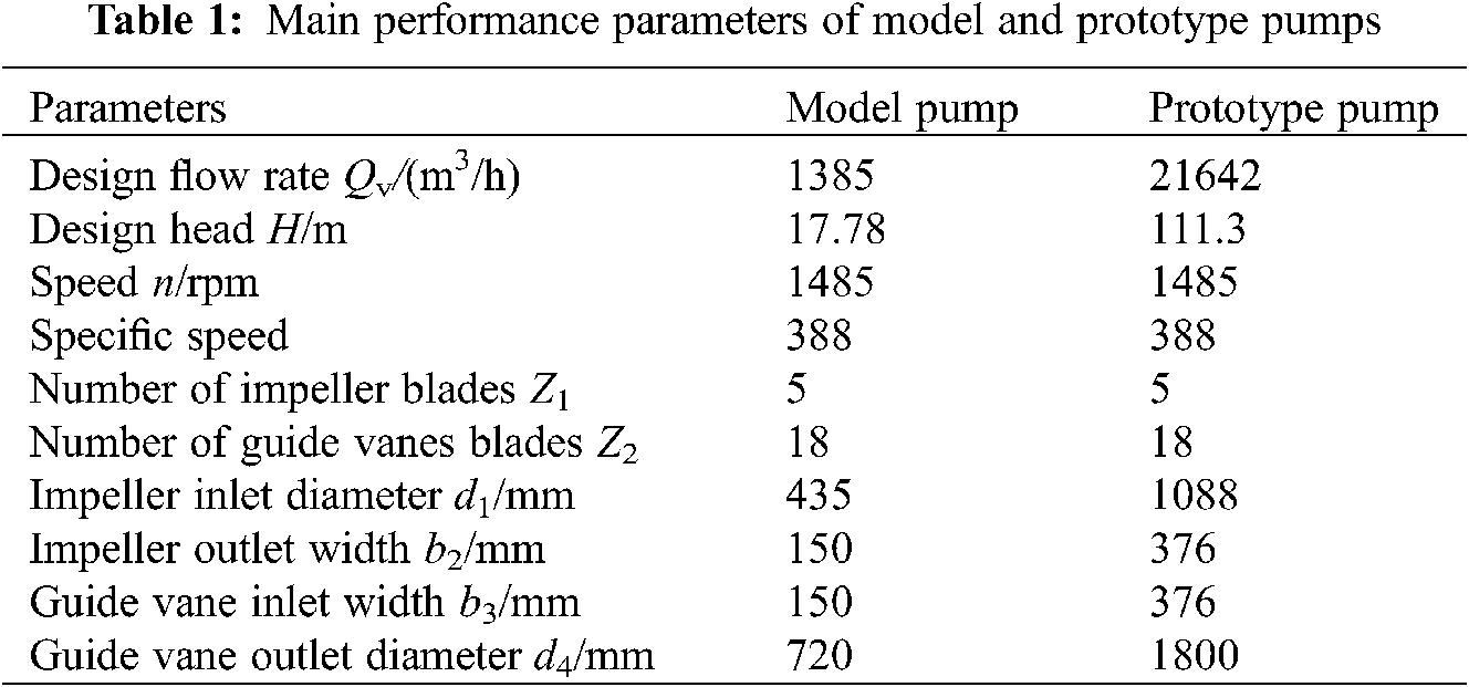
The self-designed AP1000 nuclear reactor coolant pump model is selected as the research object in this study, whose structure is shown in Fig. 1a and whose meridian plane is shown in Fig. 1b. Considering the complex structure, larger size and conveying higher temperature liquid of the prototype (real machine), the calculation with the prototype pump will inevitably lead to a series of problems such as high calculation cost and long period. Based on this, the geometric parameters of the prototype pump are designed as the simplified numerical model of the pump, and the similarity theory is used as the method, the scaling ratio λ = 0.4 is adopted [17], main performance parameters of model and prototype pumps are shown in Table 1. The radial clearance distance between the impeller outlet and the guide vane inlet increases linearly from the shroud of impeller to the hub of impeller. For the convenience of research, the intermediate value of the model pump radial clearance distance is marked as δ, and the clearance ratio between impeller and guide vane is defined as Δδ = δ/b2, where b2 is impeller outlet width.

Figure 1: Structural diagram of nuclear reactor coolant pump (a) Structure diagram of prototype pump (b) Meridian diagram
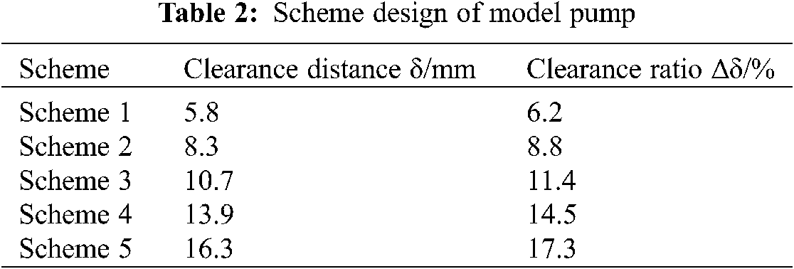
Five different schemes are designed in this study, of which Scheme 3 is the existing scheme of the model pump prototype. The clearance of the impeller and guide vane is changed by changing the leading edge of the guide vane; meanwhile every different scheme keeps the inlet blade angle of guide vane the same. The parameters of each scheme are shown in Table 2.
The entire fluid domain includes guide vane, volute, suction chamber, impeller, clearance, and inlet and outlet extension section. When it is conducted for the numerical calculation, the length of the inlet and outlet of the model pump should be appropriately increased to ensure higher calculation accuracy. The grid generation of the fluid domain is shown in Fig. 2. Since the grid density will directly affect the results of numerical calculation, the mesh independence verification travelling in the fluid domain of the model pump, the results of validation and grid refinement study are shown in Fig. 3, when the number of grids in the fluid part reaches a specific number, the head and efficiency of the model pump tend to be stable, both within 1%. Considering that the number of grids has little influence on the calculation results, it is finally determined that the grid numbers of the fluid domain are 7.21 million.

Figure 2: Fluid domain grid (a) Impeller (b) Stator and rotor cascade clearance (c) Guide vane (d) Volute
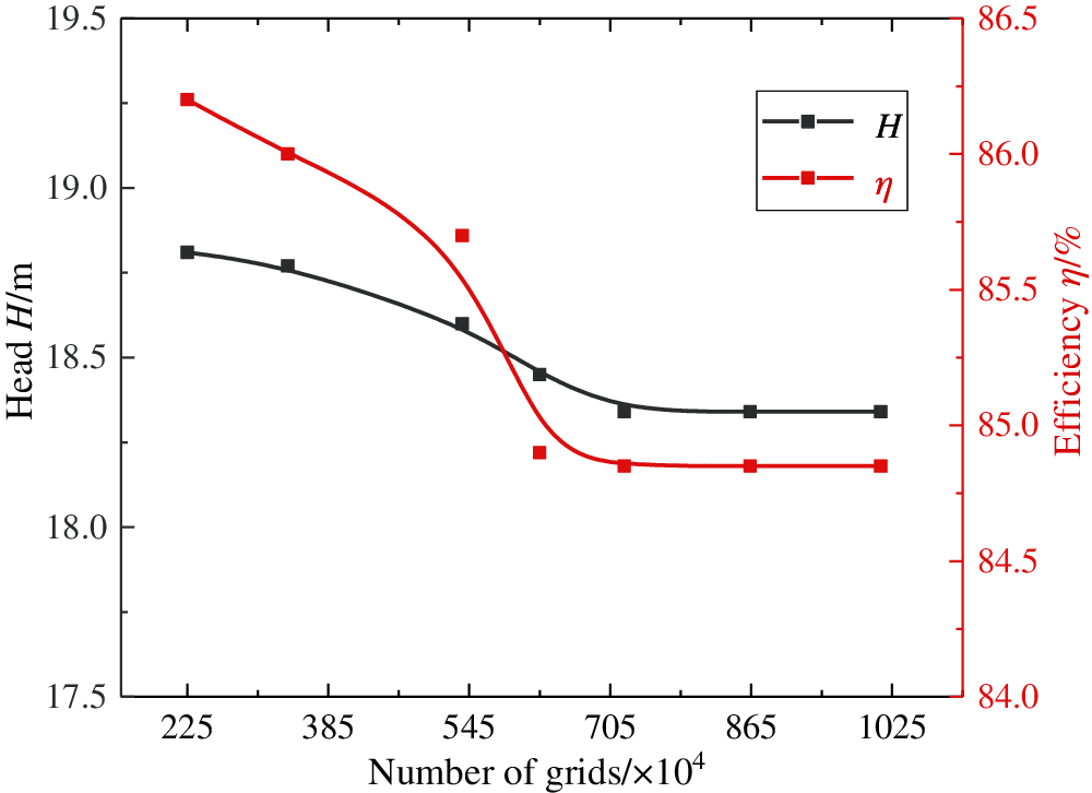
Figure 3: Mesh sensitivity analysis
Fig. 4 is the structure drawing of the coolant pump rotor in the nuclear reactor and its structure grid division. The rotor components are composed of an impeller, a rotating shaft, and upper and lower flywheels. The solid domain grid generated in ANSYS Workbench. The area of the interface involved in the data transmission is encrypted. Considering that the number and scale of grids will affect the results of rotor dynamics, therefore, different solid domain grid densities set for each part of the calculation domain, and it found that as the number of meshes in the entity domain increases, the natural frequency of the rotor system gradually decreases and stabilizes. Finally, the total number of structured grids is 1956583.

Figure 4: Solid domain grid (a) Rotor structure of reactor coolant pump (b) Grids generation of rotor structure of reactor coolant pump
3 Numerical Calculation and Model Validity Verification
3.1 Numerical Calculation Method and Mathematical Model
The incompressible Reynolds time-averaged N-S equation is used for fluid domain calculation, the second-order central difference scheme is used for the dispersion of the diffusion term, and the spread of the convection term adopts the second-order upwind system, turbulent kinetic energy and dissipation rate transport equation, to improve the calculation accuracy. Because there are both rotation and eddy in the fluid region, and the RNG k-ε model has more powerful calculation function and more minor calculation error, this study adopts a three-dimensional unsteady Reynolds averaged N-S equation, RNG k-ε turbulence model for numerical calculation [18,19]. In the iterative calculation process, determine calculation convergence by monitoring the change of total pressure of inlet and outlet pipe of the model pump. When the total pressure at the inlet and outlet of model pump tends to be stable, the calculation is considered to converge. The solid domain (Fig. 4) is calculated by using ANSYS finite element method.
The existing research shows that one-way fluid-structure interaction can meet the stress analysis requirement of the pump [20,21]. Therefore, the unidirectional fluid-solid coupling method is used to analyze the strain, stress distribution and mode of a nuclear reactor coolant pump impeller. The whole coupling calculation process is realized in Static Structural under ANSYS Workbench.
The linear equation of structural statics is:
where [K] is stiffness matrix, {x} is displacement vector, [F] is force vector.
where σ is stress matrix, [B] elastic matrix, [D] is strain matrix.
Finally, the equivalent stress is calculated according to a fourth strength theory [22,23]:
where σ1, σ2, σ3 are the three principal stresses perpendicular to each other at a point of action. σe is equivalent stress.
The boundary condition of the pump inlet is set as the velocity inlet, the outlet is set as the outflow, all the stationary walls are set as non-slip walls, and the impeller is set as rotating domain. Boric acid water is used as the calculation medium in this study, and its temperature is t = 281°C, pressure is p = 15.5 MPa (inlet pressure of the pump), density is ρ3 = 764.4 kg/m3, and the dynamic viscosity is μ = 98.32 × 10⁻⁶ kg/(m⋅s).
The supports at the two radial bearings are elastic supports that meet the actual situation. The calculation of bearing stiffness and damping coefficient adopt narrow bearing theory and Gampbell boundary conditions [24,25].
3.3 Comparison between Calculation and Test Values of External Characteristics of Model Pump
The test bench adopts a four-quadrant precision horizontal test bench. The inlet and outlet pressure collected by the pressure sensor converte to head, accuracy is ± 0.1%, and the flow rate is measured by an intelligent flow meter mounted on the pipeline of outlet, its high accuracy is ± 1.0%. The rotational speed is measured by a torque sensor that the measuring range is 0∼1,000 N⋅m and 0∼3,000 rpm, and the measurement accuracy is ± 0.3%.
There are calculation of hydraulic performance of model pump (Scheme 3) and comparison of test results in Fig. 5 for ensuring the accuracy of numerical calculations. The numerical results of the model pump’s external characteristics agree with the test results in the changing trend in the figure. However, when the relative flow rate is about Q/Qv = 0.6, there are unstable regions in the test efficiency and head, and the efficiency is relatively obvious, but there are no unstable regions in the numerical calculation, this is because the model pump will produce noticeable vibration when running at more minor flow rate condition, at the same time of vibration, a series of phenomena such as backflow and cavitation will be generated, but the influence of pulse, recirculation and cavitation on it is not considered in the numerical calculation. Meanwhile, the head value decreases gradually from smaller flow rate to larger flow rate, and the larger flow rate condition decrease ranges more significantly. The efficiency value first increases and then decreases with the increase of flow, the maximum pump efficiency value is about in the relative flow Q/Qv = 0.9. Both the test curve and the numerical calculation curve show that the maximum efficiency of the pump is not a design flow rate condition but a more minor flow rate condition, which indicates that the hydraulic of model pump needs better optimization. Underrated conditions, the relative error between the test head and the numerical calculated value at the test point is 0.58%, and efficiency is 4.3%. It can be seen that the calculation model established in this paper predicts the solution value more accurately, and we could obtain the pressure load on the impeller surface more accurately, which provides data support for the analysis of the impeller structure field.
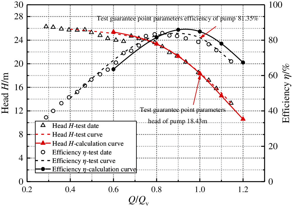
Figure 5: Comparison of numerical results and test
4 Numerical Calculation Results and Analysis
4.1 Effect of Clearance Ratio on Pump External Characteristics
Fig. 6 shows the external characteristic performance curves of nuclear reactor coolant pump under different schemes (Table 2), the conclusions can be drawn from Fig. 6a and Fig. 6b that when the nuclear reactor coolant pump with varying ratios of clearance between guide vane and impeller is running, with the change of flow rate conditions, the changing trend of head and efficiency value is basically the same. In addition, at Qv design condition, the head and efficiency both increase first and then decrease with the increase of clearance ratio, when the clearance ratio Δδ = 8.8%, the head and efficiency both reach the maximum. It can also be found from Fig. 6a and Fig. 6b, at 0.6Qv∼1.0Qv flow rate condition ranges, the clearance between guide vane and impeller has little effect on the pump efficiency value. Still, the efficiency value changes significantly with the change of clearance ratio under high flow conditions. As far as the head value is concerned, the clearance between impeller and guide vane has little influence in the flow rate condition range of 0.8Qv∼1.0Qv. After deviating from the flow rate condition ranges, the external characteristic value is more sensitive to the clearance ratio. It can also be seen from Fig. 6a that the best efficiency point does not change greatly with the difference of clearance ratio, and it appears in the range of 0.9Qv to 1.0Qv, so it is concluded that the clearance has little impact of the best efficiency point.
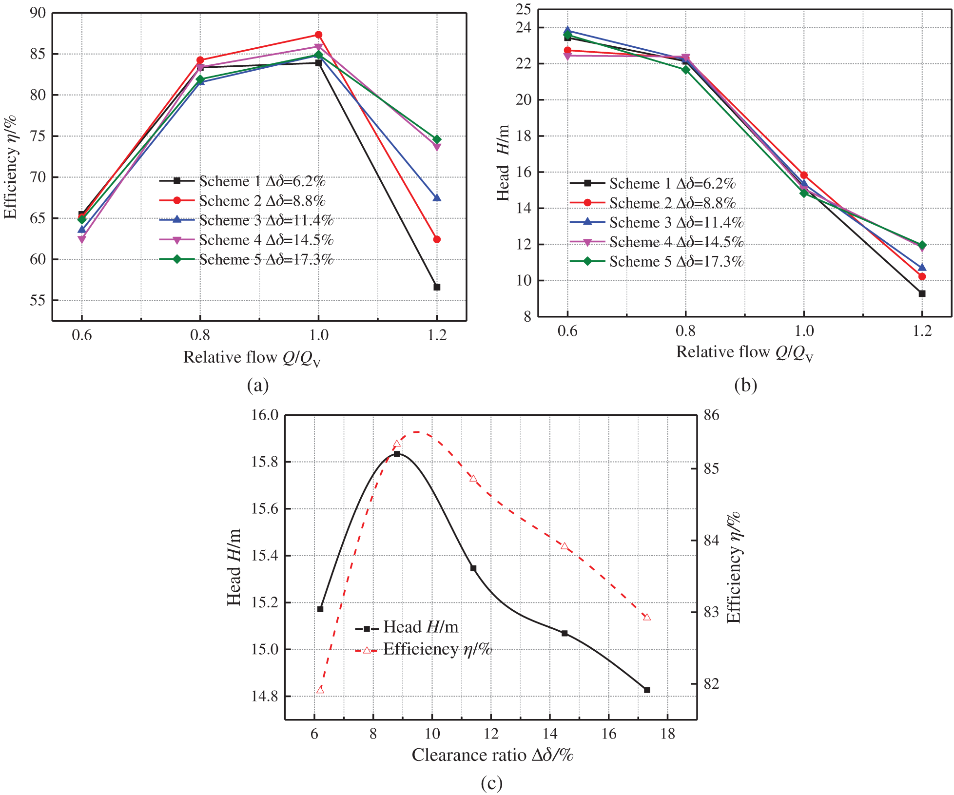
Figure 6: External characteristic curves of model pump under different schemes (a) The efficiency of different schemes under different flow rate conditions (b) The head of different schemes under different flow rate conditions (c) The influence of different schemes on the external characteristics of pump under design condition
The maximum head occurs at the clearance ratio Δδ = 8.8%, and its minimum value is at Δδ = 17.3%, the difference between the two is 1.5 m, accounting for about 8.4% of the design head. It shows that the clearance ratio has a more significant effect on the external characteristics, and there is an optimum clearance ratio.
The reasons for the performance changes of nuclear reactor coolant pump caused by different clearance ratios are analyzed as follows: Fig. 7 shows the analysis of fluid velocity triangle theory at the outlet of the impeller of the pump with varying ratios of clearance. It can be seen from Fig. 7, installation of the guide vane changes with the change of clearance ratios for inlet angle of attack α, when the clearance ratio increases, the inlet angle of attack of the guide vane also increases. When the clearance ratio between impeller and guide vane becomes larger or smaller in this study, the inlet flow angle of the guide vane will be much smaller or much larger obviously than the guide vane placement angle, which will cause the guide vane inlet to form a more significant negative or positive angle of attack that leads to deterioration of fluidity in the guide vane, the increasing impact loss, and cavitation, vortex, and the like are easily generated. Combined with the previous research, when inlet flow angle of guide vane best matches the guide vane inlet arrangement angle (the inlet flow angle is slightly smaller than the arrangement angle), the pump has the most negligible impact loss and stable flow field distribution, the nuclear reactor coolant pump can obtain the optimal hydraulic characteristics, that is, the nuclear reactor coolant pump has an optimal clearance ratio. It can be seen from Fig. 6c that in the present study, when the clearance ratio is between 8% and 10%, the head values and efficiency of the pump are the highest.
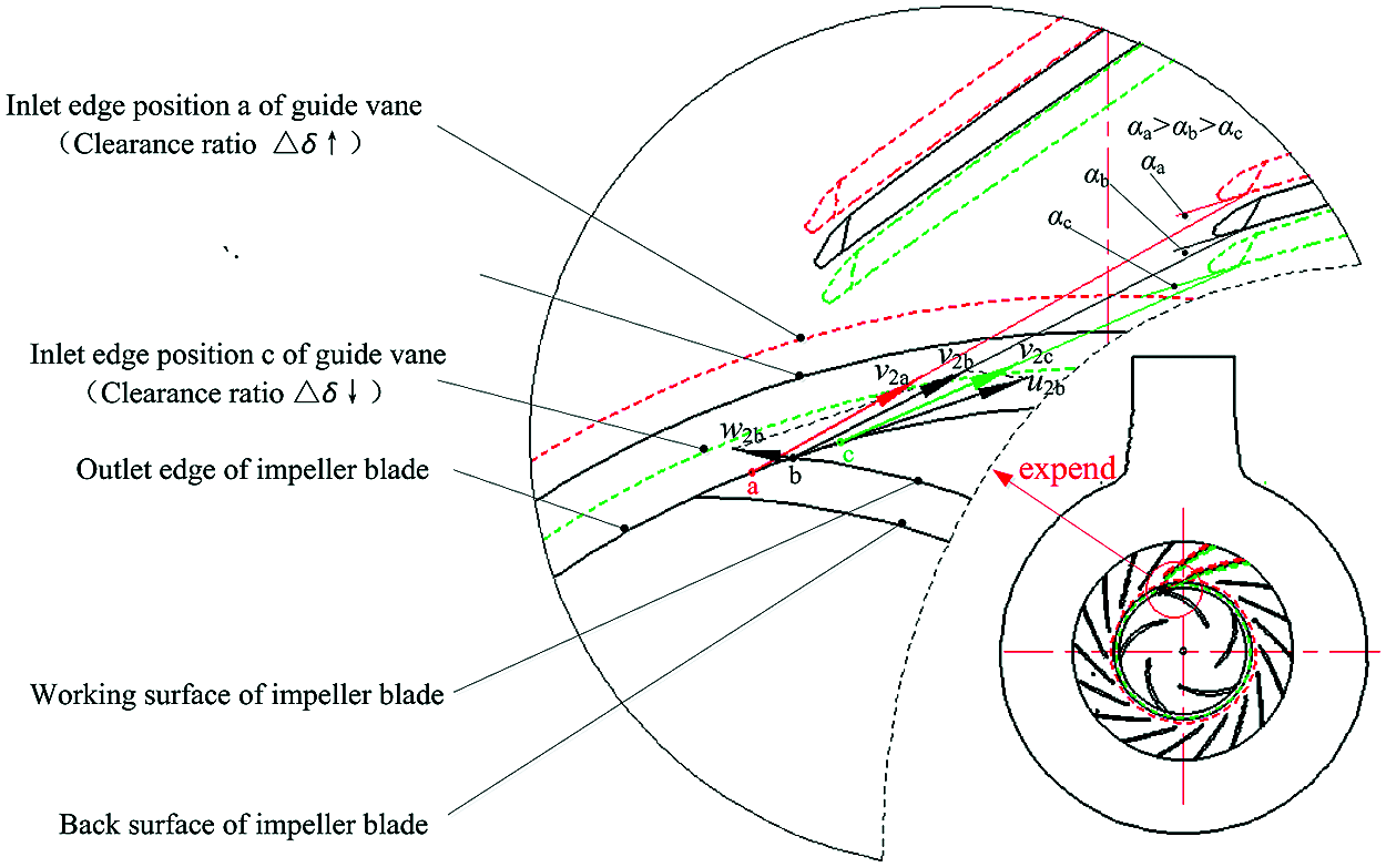
Figure 7: Velocity triangle analysis of liquid flow in a pump
Notes: In the figure, αa αb and αc represent the inlet angle of attack of the guide vane when the clearance ratio is different. Point a is the intersection of the maximum diameter of the shroud of the impeller and the working surface of the blade. Points b and c are the positions of point a when the impeller rotates through a certain angle. When the point a is at the position in the figure, the absolute velocity of the flow at point in a direction is just to point to the inlet side of the guide vane in the figure. The position of b and c is similar to that of a.
4.2 Effect of Clearance Ratio on Stress and Strain of Impeller Blades
Fig. 8 shows the influence curve of clearance ratio Δδ on maximum total deformation and maximum equivalent stress on the working surface and back of the impeller blade rated working condition. As shown in Fig. 8, the maximum equivalent stress on the working surface and the back surface of the impeller changes with the increase of the clearance ratio Δδ, but the change range of the two is different. The changing range of the working surface is smaller, while the changing range of the back surface is more extensive. When the clearance ratio Δδ = 8.8%, the maximum equivalent stress on the working surface appears to be the maximum, which is 20.068 MPa, and when Δδ = 6.2%, the minimum value is 18.537 MPa, the difference between them is 1.531 MPa; the maximum equivalent stress on the back surface of blade occurs at Δδ = 17.3%, its value is 65.147 MPa, the minimum value occurs at Δδ = 11.4%, its value is 54.244 MPa, the difference between them is 10.9 MPa. The above phenomenon shows that the change of clearance ratio Δδ has a great impact on the back surface of the blade for the maximum equivalent stress, but the effect on the working surface is minimal. The maximum equivalent stress value of the surface of the impeller blade is about three times the maximum equivalent stress of the working surface. It can also be concluded from Fig. 8 that with the increase of the clearance ratio, the maximum deformation of the working surface and the back surface of the impeller blade gradually increases. In other words, the effect of clearance ratio on the maximum total deformation of the working surface and the back of the impeller blade is consistent.
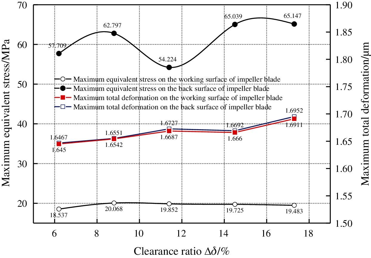
Figure 8: Stress-strain distribution on impeller blade
Fig. 9 is a distribution cloud diagram of equivalent stress and total deformation on the working surface and the back surface of the impeller blade under design condition of the clearance ratio Δδ = 6.2%. The cloud diagram analysis of total deformation and equivalent stress under other clearance ratio is similar to that in this study when the clearance ratio Δδ = 6.2%. It can be seen from Fig. 9, stress concentration appears on the working face and the equivalent stress on the back of the impeller blade, and the maximum equivalent stress appears at the impeller blade outlet connection, shroud and hub. It can be seen from the distribution of the equivalent stress on the working face and back of the impeller blade that the equivalent stress reaches the lowest in the middle region of the blade, and it indicates that the equivalent stress of the blade near the shroud and hub is more than that far away from the shroud and hub. The above phenomenon shows that the high-stress concentration area is mainly concentrated at the impeller outlet and the intersection with the shroud and the hub, so the junction between the outlet of impeller blade, shrouds and hubs are the most vulnerable parts of strength damage. This is mainly due to the higher pressure at the outlet of the impeller, resulting in a higher equivalent stress value at the outlet than at the inlet. The equivalent stress value of the area where the shroud intersects with the hub is higher than that of the middle area of the blade. Due to the limitation of the site, stress concentration is easy to cause.

Figure 9: Distribution of stress and strain on impeller blade (a) The equivalent stress distribution on working surface and back surface of impeller blade under design condition when Δδ = 6.2% (b) The distribution of total deformation on working surface and back surface of impeller blade under design condition when Δδ = 6.2%
The conclusion can be drawn from the Fig. 9b that the total deformation distribution of the blade working surface and the back are almost the same. From the intersection of the inlet edge of impeller blade and the hub to the intersection of the outlet edge of the impeller blade and the shroud, the total deformation amount varies from small to large with noticeable gradient, showing a fan-shaped distribution. Furthermore, the total deformation of the contact area between the outlet edge of the impeller blade and the shroud is the largest. The above phenomena show that the outlet edge of the impeller blade and the area near the outlet edge of the impeller blade in contact with the shroud of the impeller are vulnerable areas. The main reason is that the pressure at the inlet edge of the impeller blade is lower than the pressure at the outlet edge, and the outlet edge of the impeller blade is thinner, so the outlet deformation of the impeller blade is larger.
4.3 Effect of Clearance Ratio on Rotor Mode of the Nuclear Reactor Coolant Pump
Modal analysis is a numerical analysis technique for calculating the structural modal characteristics and the rotor dynamics research basis. Table 3 shows the first 6 natural frequencies of the structure on the nuclear reactor coolant pump rotor. The difference between the frequencies of the same order in different clearances is very small from Table 3, and the difference between the average frequencies of each order is no more than 0.03%. It could draw a conclusion that the clearance ratio has little influence on the first six natural frequencies of the nuclear reactor coolant pump rotor, because the change of clearance between guide vane and impeller will not change the rotor structure. It is well known that the blade passing frequency ƒ of the rotor of nuclear reactor coolant pump (ƒ = z × n/60 = 5 × 1485/60 = 123.75 Hz, where z is the number of blades and n is the rotational speed) is far from the first six natural frequencies of the nuclear reactor coolant pump rotor (the natural frequencies are shown in Table 3) under design condition. Therefore, under different clearance ratios, the nuclear reactor coolant pump will not produce resonance during operation under design condition, it is preliminarily determined that the rotor structure is reasonable.
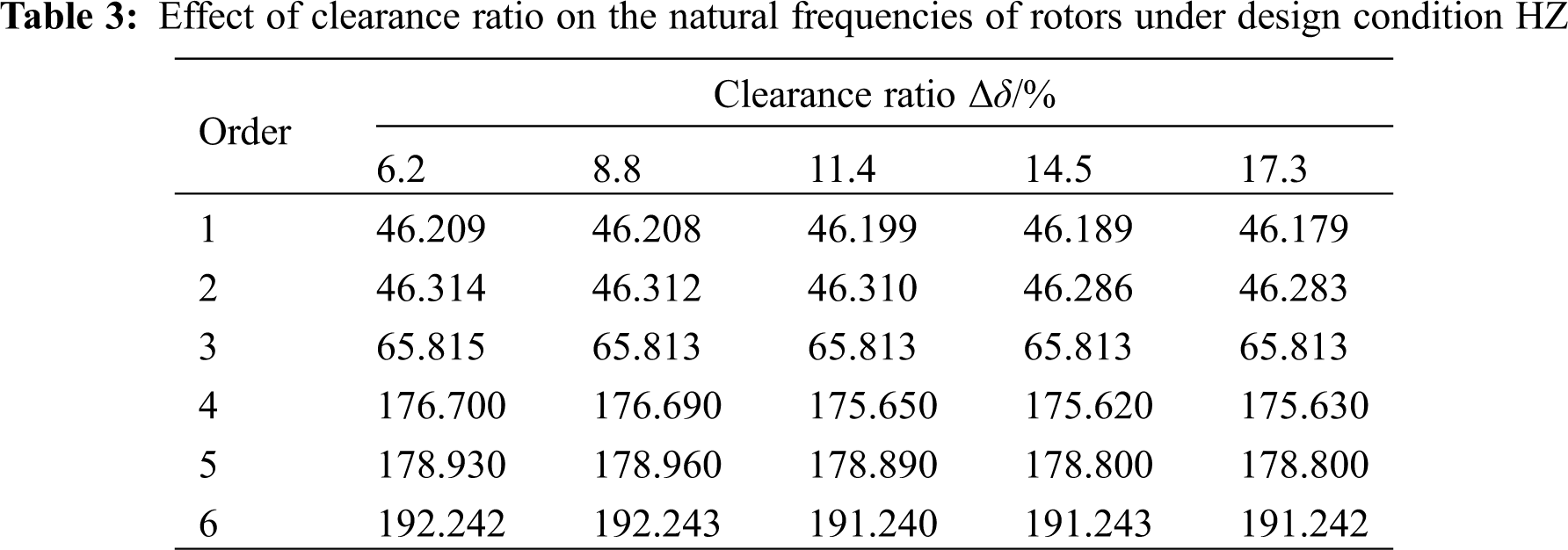
From Table 3, as can be seen, the clearance ratio has little effect on reactor coolant pump rotor modalities, so the original nuclear reactor coolant pump model (clearance ratio Δδ = 11.4%) is selected for modal analysis. Fig. 10 shows the first six vibration modes of the original nuclear reactor coolant pump model rotor system under design condition. It can be seen from Fig. 10 that as the order of the vibration mode increases, the real deformation of the rotor decreases, and the total deformations of the first and second orders are the largest and their values exceed 11 μm. It can be seen that the first-order bending vibration has the most significant influence and the most potent destructive force on the nuclear reactor coolant pump rotor. It also can be seen from Fig. 10 that the first three orders are mainly the overall vibration of the impeller, and the last three orders are the overall vibration of the impeller and flywheel. The first-order and second-order modes are the same in that they both bend and vibrate along an axis, but they are different in that they bend and oscillate along the x-axis and y-axis, respectively. The third-order mode is the torsional vibration of the impeller around the z-axis. The fourth-order and fifth-order modes are the same in that they both bend and vibrate along the y and x-axis simultaneously. The sixth-order mode is the torsional vibration of the impeller and the lower flywheel around the z-axis. Combined with Table 3, the higher the order, the higher the modal frequency of the nuclear reactor coolant pump, the first-order and second-order, fourth-order and fifth-order modes of the rotor system are the same, and the natural frequencies are very close. The phenomenon of this formation in pairs is related to the axisymmetric flow in the impeller field, because the axisymmetric flow mode has a multiple root mode.

Figure 10: The first 6 order mode shapes of the rotor under design conditions when Δδ = 11.4% (a) First-order mode shapes (b) Second-order mode shape (c) Third-order mode shape (d) Fourth-order mode shape (e) Fifth-order mode (f) Sixth-order mode shape
The unidirectional fluid-structure coupling method is used to analyze the influence of fluid-structure coupling under different gaps on the pump characteristics and rotor mode of the AP1000 nuclear reactor coolant model, revealing the stress and deformation laws of the impeller. First of all, the superficial characteristics are the basis to reflect the comprehensive performance of the pump. After calculating the influence of different clearances on the external characteristics, there is an optimal clearance ratio to maximize the head and efficiency. After that, the law of the clearance to the impeller blade stress and strain is analyzed. The stress and strain on the back surface of the impeller blade are more sensitive, especially the stress, the maximum equivalent stress occurs at the intersection of the impeller blade outlet edge, shroud and hub. Next, the influence of clearance ratio on rotor mode is analyzed, it is found that the change of clearance ratio will not change the natural frequency of rotor mode, and it can be confirmed that there is no resonance by comparing the blade passing frequency. Finally, the first six orders modes are calculated, the first three orders modes are mainly the whole vibration of the impeller, and the last three orders modes are the whole vibration of impeller and flywheel. In short, the change of clearance ratio will significantly change the stress and strain of the blade back surface and blade working surface, and the vibration generated by the nuclear reactor coolant pump during operation can be well reduced by changing the clearance.
(1) The clearance ratio between impeller and guide vane affects the external characteristics parameters of the nuclear reactor coolant pump, which varies with changing the clearance ratio.
(2) Within the set clearance ratio range, in the design flow rate condition, the clearance ratio has a more significant influence on the maximum equivalent stress on the rear surface of the impeller blade. It has less impact on the working surface. The maximum equivalent stress value on the back surface of the impeller blade is about three times on the working surface. The maximum total deformation of the blade’s working surface and back is affected by the clearance ratio and increases with the increase of the clearance ratio. The outlet side of the impeller and its intersection with the hub and shroud of the impeller is concentrated areas with enormous stress value and which also have a large total deformation. The total deformation varies obviously from small to large, showing a fan-shaped distribution.
(3) Within the set clearance ratio range, the clearance ratio is almost no effect on the first six natural frequencies of the rotor for the nuclear reactor coolant pump. The first three orders are the overall vibration of the impeller and the last three orders are the overall vibration of the impeller and the lower flywheel.
Therefore, in the practical application process, the clearance between the guide vane and impeller should be designed to prevent the improper clearance from causing blade inlet fatigue damage or blade outlet edge deformation, causing greater vibration, affecting the stable operation of the pump.
Funding Statement: This work is supported by the National Natural Science Foundation of China (No. 51469013).
Conflicts of Interest: The authors declare that they have no conflicts of interest to report regarding the present study.
1. Paidoussis, M. P. (1983). A review of flow-induced vibrations in reactors and reactor components. Nuclear Engineering and Design, 1, 31–60. DOI 10.1016/0029-5493(83)90138-3. [Google Scholar] [CrossRef]
2. Inada, F. (2015). A study on leakage flow induced vibration from engineering viewpoint. ASME 2015 Pressure Vessels and Piping Conference. Boston: American Society of Mechanical Engineers Digital Collection. DOI 10.1115/PVP2015-45944. [Google Scholar] [CrossRef]
3. Hirano, T., Guo, Z., Kirk, R. G. (2005). Application of computational fluid dynamics analysis for rotating machinery—Part ii: Labyrinth seal analysis. Journal of Engineering for Gas Turbines and Power, 127(4), 820–6. DOI 10.1115/1.1807415. [Google Scholar] [CrossRef]
4. Zhang, M., Wang, X. F., Xu, S. L., Wan, X. (2014). Analysis of the stiffness coefficient of the incompressible fluid seal for pump. Journal of Harbin Engineering University, 3, 347–352. [Google Scholar]
5. Will, B. C., Benra, F. K., Dohmen, H. J. (2012). Investigation of the flow in the impeller side clearances of a centrifugal pump with volute casing. Journal of Thermal Science, 21(3), 197–208. [Google Scholar]
6. Li, Z. L., Xu, S. L., Guan, Z. Q. (2018). Study on axial vibration characteristics of impeller clearance of nuclear main pump. Journal of Computational Mechanics, 35(4), 458–465. [Google Scholar]
7. Parikh, T., Mansour, M., Thevenin, D. (2020). Investigations on the effect of tip clearance gap and inducer on the transport of air-water two-phase flow by centrifugal pumps. Chemical Engineering Science, 218, 115554. [Google Scholar]
8. Thamsen, B., Plamondon, M., Granegger, M., Daners, S., Kaufmann, R. et al. (2018). Investigation of the axial gap clearance in a hydrodynamic-passive magnetically levitated rotary blood pump using X-ray radiography. Artificial Organs, 42(5), 510–515. [Google Scholar]
9. Mansour, M., Wunderlich, B., Thévenin, D. (2018). Effect of tip clearance gap and inducer on the transport of two-phase air-water flows by centrifugal pumps. Experimental Thermal and Fluid Science, 99, 487–509. [Google Scholar]
10. Liu, Y. B., Tan, L., Hao, Y., Lu, L. (2017). Energy performance and flow patterns of a mixed-flow pump with different tip clearance sizes. Energies, 10(2), 191. DOI 10.3390/en10020191. [Google Scholar] [CrossRef]
11. Cheng, X. R., Lv, B. R., Ji, C. Y., Dorah, N. (2020). Influence of circumferential placement position of guide vanes on performance and dynamic characteristics of nuclear reactor coolant pump. Mathematical Problems in Engineering, 2020, 3786745. DOI 10.3901/JME.2016.16.197. [Google Scholar] [CrossRef]
12. Key, N. L., Lawless, P. B., Fleeter, S. (2010). An experimental study of vane clocking effects on embedded compressor stage performance. Journal of Turbomachinery, 132(1), 011018. DOI 10.1115/1.3072714. [Google Scholar] [CrossRef]
13. Wang, X. L., Lu, Y. G., Zhu, R. S., Yu, H., Chen, Y. (2019). Study on bidirectional fluid-solid coupling characteristics of reactor coolant pump under steady-state condition. Nuclear Engineering and Technology, 51(7), 1842–52. DOI 10.1016/j.net.2019.05.009. [Google Scholar] [CrossRef]
14. Chen, X. C., Zheng, Y., Xu, J. H., Jiang, T. (2020). Fatigue life study of francis pump under reverse generation condition based on fluid solid coupling. Water, 12(4), 1162. DOI 10.3390/w12041162. [Google Scholar] [CrossRef]
15. Zhang, F. X., Zheng, Y., Yang, C. X., Jin, X. L., Ding, L. (2012). Stress analysis of tubular turbine based on fluid-structure coupling. Applied Mechanics and Materials, 190, 1261–1265. DOI 10.4028/www.scientific.net/AMM.190-191.1261. [Google Scholar] [CrossRef]
16. Wu, H. J., Guo, P. C., Liao, W. L. (2004). Application of ANSYS to fluid-solid coupling vibration analysis for component of hydraulic turbines. Hydroelectric Energy, 4(4), 64–66. [Google Scholar]
17. Li, Y. B., Li, R. N., Wang, X. Y., Hu, P. L., Qi, Y. N. (2015). Scaling effect for hydraulic performance prediction of nuclear main pump. Atomic Energy Science and Technology, 49(4), 609–15. [Google Scholar]
18. Liu, H. L., Liu, D. X., Wang, Y., Wu, X., Zhuang, S. (2012). Applicative evaluation of three cavitating models on cavitating flow calculation in centrifugal pump. Transactions of the Chinese Society of Agricultural Engineering, 28(16), 54–59. [Google Scholar]
19. Cheng, X. R., Lv, B. R., Zhang, X. L., Wei, Y. Q., Wang, P. (2018). Influence of outlet edge position of guide vane on performance of well submersible pump. Transactions of the Chinese Society of Agricultural Engineering, 34(10), 68–75. [Google Scholar]
20. Liu, H. L., Xu, H., Wu, X. F., Wang, K., Tan, M. G. (2012). Effect of fluid-solid interaction on internal and external characteristics of centrifugal pump. Transactions of the Chinese Society of Agricultural Engineering, 28(13), 82–87. DOI 10.3969/j.issn.1002-6819.2012.13.014. [Google Scholar] [CrossRef]
21. Alaimo, A., Esposito, A., Messineo, A., Antonio, A., Messineo, A. (2015). 3D CFD analysis of a vertical axis wind turbine. Energies, 8(4), 3013–3033. DOI 10.3390/en8043013. [Google Scholar] [CrossRef]
22. Trivedi, C. (2017). A review on fluid structure interaction in hydraulic turbines: A focus on hydrodynamic damping. Engineering Failure Analysis, 77, 1–22. DOI 10.1016/j.engfailanal.2017.02.021. [Google Scholar] [CrossRef]
23. Yang, J., Preidikman, S., Balaras, E. (2008). A strongly coupled, embedded-boundary method for fluid–structure interactions of elastically mounted rigid bodies. Journal of Fluids and Structures, 24(2), 167–82. DOI 10.1016/j.jfluidstructs.2007.08.002. [Google Scholar] [CrossRef]
24. Rao, T. V., Rani, A. M., Mohamed, N. M., Ya, H. H., Hashim, F. M. (2019). Analysis of magnetohydrodynamic partial slip laser bump texture slider and journal bearing. ARCHIVE Proceedings of the Institution of Mechanical Engineers Part J Journal of Engineering Tribology 1994–1996, 233(12), 1921–38. DOI 10.1177/1350650119852568. [Google Scholar]
25. Fan, T. S., Hamzehlouia, S., Behdinan, K. (2017). The effect of lubricant inertia on fluid cavitation for high-speed squeeze film dampers. Journal of Vibroengineering, 19(8), 6122–34. DOI 10.21595/jve.2017.19314. [Google Scholar] [CrossRef]
 | This work is licensed under a Creative Commons Attribution 4.0 International License, which permits unrestricted use, distribution, and reproduction in any medium, provided the original work is properly cited. |