| Fluid Dynamics & Materials Processing |
DOI: 10.32604/fdmp.2022.017523
ARTICLE
An Experimental and Numerical Study on the Cleaning of Pleated Bag Filters Using Low-Pressure Pulsed-Jets
1School of Energy and Environment, Anhui University of Technology, Ma’anshan, 243002, China
2School of Civil Engineering and Architecture, Anhui University of Technology, Ma’anshan, 243002, China
3Suzhou Hengqing Environmental Protection Technology Co., Ltd., Zhangjiagang, 215600, China
*Corresponding Author: Fuping Qian. Email: fpingqian@ahut.edu.cn
Received: 17 May 2021; Accepted: 26 July 2021
Abstract: Pulsed-jet cleaning is recognized as the most efficient method to regenerate bag dust collectors traditionally used in industrial processes to control the emission of particulates. In this study, non-woven needle felt filter bags with and without a film coating material have been analyzed considering different geometries (different number N of pairs of pleated filter bag sides) in the frame of dedicated low-pressure pulsed-jet cleaning experiments. The flow structure inside the bag and the response characteristics of its wall have also been analyzed numerically through a computational fluid-dynamics/structural-dynamics (CFD-CSD) unidirectional fluid-solid coupling method. As shown by the experiments, the peak pressure (P0) on the wall of the filter bag with N = 8 and 12 is higher, which indicates dust can be removed more effectively in these cases. The peak pressure on the wall increases first and then decreases along the direction of the bag length, while the peak pressure of the pleated filter bag with non-woven needled felt film coating is greater than that without film coating. A comprehensive analysis of the time variation of acceleration, deformation, strain, stress and other factors, has led to the conclusion that the pleated filter bag with N = 12 would be the optimal choice.
Keywords: Pleated filter bag; dust cleaning performance; low-pressure pulsed-jet cleaning; peak pressure; unidirectional fluid-structure coupling
Steel, cement, mining and other industrial processes can produce a large amount of dust, and the problem of severe air pollution caused by dust emissions has attracted great attention [1–3]. Bag dust collector is commonly recognized as the most effective method to deal with particulates such as smoke and dust. The early filter bag structure is mainly straight round bag, which is difficult to break through the problems of high discharge, high breaking rate and large equipment covering. With the continuous improvement of environmental protection requirements, the limits of industrial and mineral dust emission are increasingly strict. The pleated filter bag is a special-shaped filter bag made by sewing a circle of wavy folds evenly along the circumference of a round bag. Comparison of the round bag, an increase of specific surface area is more than 50%. Dust removal of pleated filter bags not only contributes to dust emissions, but also effectively improves the technical economy of the dust collector [4,5]. Moreover, it has certain advantages in land occupation, energy saving and consumption reduction, and transformation investment [6].
Dust cleaning is the key to the operation of the dust collector in industrial dedusting system, which directly affects the dust cleaning efficiency of the dust collector and the operation resistance of the system. Pulsed-jet cleaning is a method developed rapidly in the 1960s, which has the advantages of low gas consumption, easy control and maintenance, simple structure, high dust cleaning efficiency, energy saving and environmental protection [7]. Therefore, it has been widely used to filter dust cleaning [8–10].
Most researches on dust collectors focused on round filter cartridges and filter bags, while few researches on structural design and optimization of dust cleaning performance of pleated filter bags. However, the design of pleated filter bag is similar to that of pleated filter cartridge, so this study can still learn from the related research of pleated filter pulse cleaning. Many scholars [11–14] improved the dust cleaning effect by changing the structure of the pulsed-jet cleaning system, such as built-in rotation, injection distance, nozzle diameter, nozzle type, pulsed-jet cleaning type, pleated structure and so on. Some studies [15–19] indicated that changing the parameters of the pulsed-jet cleaning system, such as the cleaning algorithms, tank pressure, pulse width, filter media, maximum allowable pressure drop, and cleaning mode, can improve the dust cleaning performance. Chen et al. [20–22] and other scholars studied the transient static pressure field of four-fold pleated filter cartridges during pulsed-jet cleaning. The results showed that the static pressure on the surface of trapezoidal filter cartridges was the most uniform, and the peak pressure near the pleat tip was the highest. Their numerical study also reported the effect of cylinder shape on dust cleaning performance of pulsed-jet pleated filter cartridges. Li et al. [23] and other researchers found that the greater the peak pressure inside the filter cartridge, the less the residual dust attached to the surface of the filter cartridge. Pulsed-jet cleaning airflow would cause the filter bag to shake and deform violently, which would produce great stress, and the flow field in the filter bag would change very quickly. Obviously, moderate cleaning is beneficial to improve the uniformity of dust cleaning and prolong the service life of the filter bag. Rocha et al. [24] adopted computational fluid dynamics (CFD) numerical simulation method to study the gas inlet position of circular filter bag, in order to support the search for more efficient and durable equipment design. Chen et al. [13] and other scholars carried out 3D transient modeling of a single-cartridge filtration system. The static pressure difference across pleated filter media and peak static pressure were analyzed to study the effect of using annular-slit nozzle on the efficiency of reverse flow cleaning, especially at the top region of pleated filter cartridges. Andersen et al. [25] and other researchers also adopted CFD and experiments to study the pulsed-jet cleaning system. Experimental pressure measurements are used as validation data for the full three-dimensional (3D) CFD model, which also is used to investigate the basic physics of subsonic/supersonic pulsed-jet cleaning, the jet behavior and the effect of the venturi in relation to a typical pulse-jet cleaned fabric filter. Park et al. [26] and other scholars numerically investigated flow characteristics along a bag filter in detail. And found that the filtration velocity was non-uniform along the axial direction of a long bag filter when the height of the filter was greater than 10 m. The filtration velocity was very small at the bottom of the bag filter but very large at the top. Qiu et al. [27] established in the pressure field of cleaning flow in the conical pleated filter, and studied the effect of cone height on the cleaning performance. Jin et al. [28] explored the impact of pulse intervals on dust cleaning performance, and compared the dust cleaning performance with positive and reverse order of online dust cleaning mode. Simon et al. [29] photographed the movement of the filter bag in the initial stage of pulse dust cleaning with a high-speed camera, and thought that most of the dust shedding mainly depended on the acceleration of the filter bag. Humphries et al. [30] considered that the main factors affecting the dust cleaning force were the peak pressure and the peak pressure arrival time, and the greater the pressure on the filter bag and the shorter the stress time, the greater the dust separation force. Li et al. [31] has also studied the movement of filter bags in the dust removal. Obviously, for convenience, the previous numerical studies on pulsed-jet cleaning of pleated filters mostly assumed that the filter medium did not deform, which failed to fully reflect the changes in the dust cleaning process caused by deformation of filter bags.
In this study, non-woven needle felt filter bags with and without a film coating material have been analyzed considering different geometries (N = 8, 10, 12) in the frame of dedicated low-pressure pulsed-jet cleaning experiments. And then three-dimensional geometric models of flow field and structure field are established based on CFD-CSD unidirectional fluid-structure coupling method. Next, numerical simulation calculation of airflow distribution inside the bag and transient structural dynamics calculation of pleated filter bag are conducted to analyze the flow structure inside bag and the response characteristics of its wall in the low-pressure pulsed-jet cleaning process. Finally, the dust cleaning performance of pleated filter bag with different pleats is studied with multiple indexes (wall peak pressure, acceleration, deformation, stress and strain) to provide basis for performance optimization of pleated filter bag.
2 Experimental and Numerical Study on Dust Cleaning Performance of Pleated Filter Bag
2.1 Experimental Equipment and Scheme
As shown in Fig. 1, the experimental setup consists of an air supply system, a blowing system, and a data acquisition system, including an air compressor (screw air compressor), an air bag (Q235-B, a volume of 0.046 m3, and a maximum working pressure of 0.7 MPa), DMF-Z-25S electromagnetic pulse valve, LXG-16M pulse controller, 1,000 mm long, 20 mm inner diameter blowing pipe, blowing hole size Φ8 mm, power supply, 3 wind pressure transmitters (YW-130 type, Measurement range −10–10 kPa), Advantech USB-4716 data acquisition card, PC equipped with LabView14.0 software [32]. The size of the filter chamber is 1,000 mm (length) × 460 mm (width) × 1,295 mm (height). The pleated filter bag with a diameter of 160 mm and a height of 1,050 mm was installed in the filter chamber.
In this experiment, the pulse controller was used to drive the dust cleaning process. After the pulse valve opened, compressed air was rapidly sprayed into the filter media in a transient injection time (no more than 0.2 s). At the same time, by inducing the surrounding air several times as much as the injection air into the pleated filter bag, the internal pressure of the filter bag was raised to produce violent expansion and impact vibration to deform and break the dust layer, thus realizing the dust cleaning effect. Therefore, in order to study the dust cleaning performance of pleated filter bags with different pleats, the designed experimental conditions in this study are summarized in Table 1. Pressure sensors were used to measure the peak pressure P0 at each measuring point. P0 signal was transmitted to the computer running LABVIEW through the acquisition card of Advantech USB-4716 for synchronous recording. In the process of data analysis, the collected data was converted into pressure data by Eq. (1):
where pressure sensor measuring range −10–10 kPa, output electrical signal 0–10 V; X is output voltage value during data acquisition (V). Y is peak pressure value after conversion (Pa).
The experimental operation parameters are shown in Table 1. The conditions (the injection pressure of 0.3 MPa (Low pressure range of low pressure pulse cleaning is 0–0.4 MPa), the injection time of 200 ms, the nozzle diameter of 8 mm, and injection distance (H) of 25 mm) are selected to measure the peak pressure at each measuring point of six groups of pleated filter bags with pleat number N = 8, 10 and 12, and non-woven needle felt filter bag with and without a film coating material covered respectively. And each test condition is tested 3–6 times. As shown in Fig. 1, the measuring points are evenly arranged to observe the movement along the length direction of the bag.
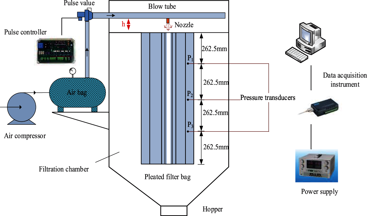
Figure 1: Schematic diagram of the experimental setup
2.2 Numerical Study on Dust Cleaning Performance of Pleated Filter Bag
Pulsed-jet bag dust collector cleans the filter bag by blowing, however, the filter bag is easy to be damaged under the impact of pulse jet, thus shortening its service life. It is necessary to investigate the characteristics of flow field and structure field of filter bag in the process of pulsed-jet dust cleaning [33,34]. Therefore, in the multi-physical field coupling function of Ansys Workbench in this study, the three-dimensional geometric models of flow field and structural field of pleated filter bags are established accordingly based on CFD-CSD unidirectional fluid-structure coupling method. Moreover, the flow structure inside bag and the transient structural dynamics calculation of pleated filter bags have also been analyzed numerically through ANSYS Fluent module and Transient Structural module. Then, the flow structure inside the bag with different folds and the response characteristics of its wall have also been analyzed, which can be used to promote the structural design and improve the dust cleaning performance of the fold filter bags.
2.2.1 Geometric Model and Meshing
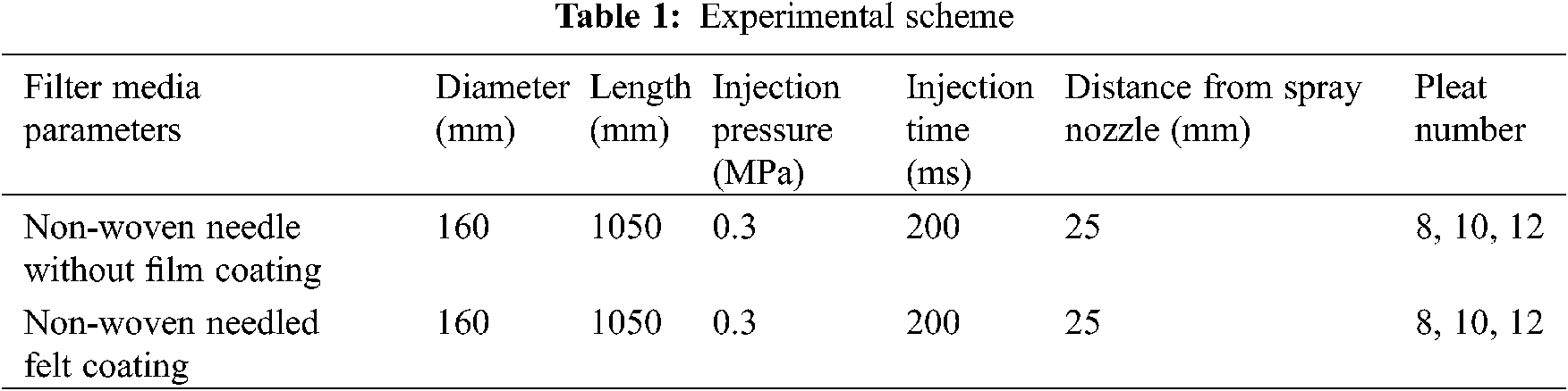
There are mainly four basic assumptions of the dust cleaning model. Firstly, the velocity of the pulse injection airflow is evenly distributed along the radial direction of the nozzle and flows in an unsteady state. Secondly, the air in the filter bag chamber is a compressible fluid at room temperature, where the effect of gravity and the slip of wall surface are ignored. Thirdly, the filter bag is a flexible film without a skeleton in order to facilitate the finite element analysis. Finally, the filter bag is in a clean state that the permeability variations of the filter media affected by dust are not considered [27,35]. Figs. 2a–2c are the physical model of the dust cleaning, the meshing distribution of the flow field and the filter bag meshing division of the structure field, respectively.
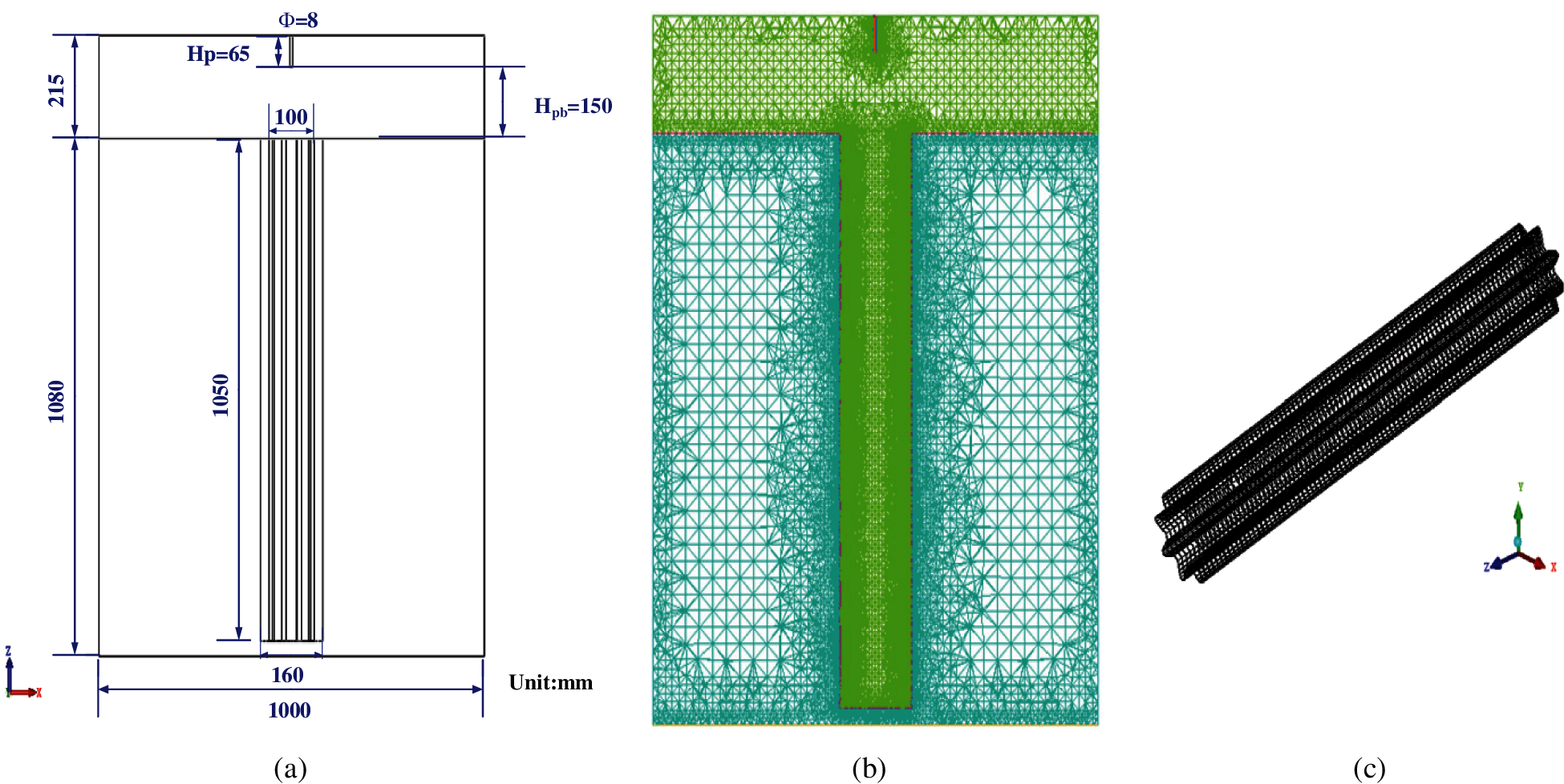
Figure 2: Physical model and meshing of pleated bag dust collector (a) physical model (b) meshing (c) filter bag meshing division
2.2.2 Grid Independence Verification
Fig. 3 shows the change of the maximum pressure at the pleated filter bag of N = 8 with the number of grid points. It can be seen that the maximum pressure first increases and then decreases as the number of grid points increases, and gradually stabilizes. Within a certain range, the number of grid points has little effect on the pressure drop at the inlet and outlet of the system. In view of the fact that too large number of grid points will increase the calculation time, this article adopts about 830,000 grids for numerical simulation, the number of grid points is moderate and the grid quality is 0.39~1.0.
Figure 3: The change of the maximum pressure at the pleated filter bag of N = 8 with the number of grid points
2.2.3 Flow Field Numerical Calculation Model and Boundary Conditions
The numerical calculation of the flow field adopted the 3D unsteady flow mathematical model and the standard k-ε equation turbulence model. The governing equations mainly include the mass equation, momentum equation, energy equation, turbulent kinetic energy k equation and dissipation rate ε equation [36,37].
The continuity equation of fluid flow can be derived from the law of conservation of mass [38]:
where
According to Newton’s second law, the momentum equation of the fluid can be derived:
where p is pressure, τij is stress tensor, Fx, Fy, Fz are the volume force acting on the x, y, and z directions of the infinitesimal bodys, respectively, N, and the volume force F = 0.
The standard k-ε model with high stability and calculation accuracy is used to solve the governing equations. The calculation equations are as follows [39]:
Turbulent kinetic energy k equation:
Dissipation rate ε equation:
where Gk depicts the turbulent kinetic energy generated by the average velocity gradient, Gb represents the turbulent kinetic energy caused by buoyancy, YM is the influence of compressible turbulent pulsating expansion on the total dissipation rate, C1ε = 1.44, C2ε= 1.92, C2ε= 0.09, σk and σε are Prandtl numbers corresponding to turbulent kinetic energy and turbulent dissipation rate, respectively.
Therefore, based on the pressure solver, this study used the SIMPLE algorithm, the first-order upwind equation, the compressible 3D steady-state flow mathematical model and the standard k-ε turbulence model for the numerical calculation of the gas flow field.
The boundary conditions applied in this study are summarized in Table 2 and are briefly described as follows. Wall boundary conditions were applied to the solid regions including the wall of the dust collector, at the nozzle, and at the bottom, i.e., the closed end, of the pleated filter. A no-slip boundary conditions were adopted at the wall surface by default in Fluent modeling. In this study, air was used in the fluid domain [40]. The pressure inlet was set as the nozzle inlet with the low injection pressure of 0.3 MPa (gauge pressure), while the pressure of the outlet was set as the bottom of the dust removal box of 0 (gauge pressure). The boundary condition of the filter bag area was set as the porous jump, where the thickness, permeability and the pressure order coefficient were 2 mm, 6.5 × 10⁻¹¹ m2 and 0, respectively. The injection time was set 0.2 s. The gas phase field was simulated numerically, and the flow field distribution in the pleated filter bags with length of 1.05 m and pleat numbers of N = 8, 10 and 12 was obtained under the action of pulsed-jet.
2.2.4 Structural Field Numerical Calculation Model and Boundary Conditions
The numerical calculation of the structure field applied the unidirectional fluid-solid coupling method, and the pressure data calculated from the flow field was transferred to the structure field in the form of load to analyze the dynamic response characteristics of the pleated filter bag under the action of jet air. The CSD governing equation mainly includes constitutive equation [41] and motion equation [42]. The former is a physical equation describing the stress-strain relationship, while the latter describes the acceleration and deformation of the filter bag under the action of pulsed-jet. The mathematical expressions are as follows:
(1) Constitutive equation
where εφ and εz represent the circumferential and axial linear strain, mm, E is elastic modulus, Pa, μ is Poisson’s ratio, σφ and σz represent the circumferential and axial line stress, respectively, Pa.
(2) Motion equation
where M, C and K represent the mass matrix, damping matrix and stiffness matrix of the filter bag respectively,
The boundary conditions of transient dynamics calculation mainly include constraint conditions such as material properties, displacement limitation and load application. At first, the thickness, density, elastic modulus and Poisson’s ratio of filter media were set 2 mm, 263 kg·m−3, 20 MPa and 0.26, respectively. Then, the structural field analysis time was set to be unified with the flow field solution time. In view of the small circumferential gap between the wall of the filter bag and the bag cage in engineering application, the bottom of the bag was set as the fixed bearing surface, and only the displacement caused by radial deformation was considered on the wall of the filter bag. Finally, the pressure of the filter bag area in the flow field was loaded on the corresponding surface of the pleated filter bag in the structure field.
3.1 Experimental Results and Analysis
Fig. 4 shows the pressure curve at point 1 (p1) of the pulsed-jet experiment. It can be seen that the instantaneous positive pressure peak appears and then the negative pressure value appears at p1. This is mainly due to the rapid ejection of compressed air from the air bag under the control of the pulse controller to induce the surrounding air flow into the bag, which makes the filter bag appear instantaneous positive pressure, and the upper part of the pleated filter bag will generate a large negative pressure in a transient injection time due to the high air flow speed.
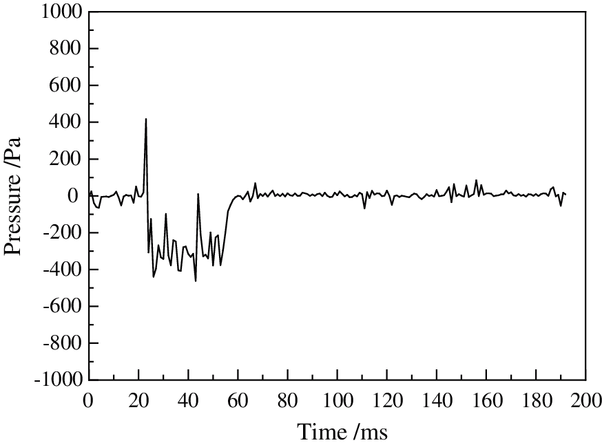
Figure 4: Pressure measured curve of pulse injection experiment at p1
The pressure peak variations of the three groups of filter bags with different numbers of pleats are shown in Fig. 5. It can be seen that the peak pressure value of non-woven needled pleated filter bag with film coating is higher than that without film coating because the coated filter material is a composite filter material covered the surface of needled felt with microporous film [43]. And the permeability of the filter material of non-woven needled felt with film coating is reduced due to the existence of microporous film in the process of pulse dust cleaning, so it is difficult to quickly attenuate when the air flow is blown onto the surface of the filter media, and it will suffer a greater pressure. And on the conditions of the same filter material and the measuring point position, the pressure peaks of the side walls of the filter bag with different numbers of pleats are different. The filter bag pressure peaks of N = 8 and 12 are higher than that of N = 10, thus the dust cleaning effect of N = 8 and 12 is relatively good. The pressure peak of the side wall at p2 is obviously greater than that of p1 and p3, so the peak pressure increases first and then decreases along the length of the bag for the same filter bag with the same filter media and pleats. This is attributed that the restricted jet in the bag to expand near the bag mouth causes the peak pressure value to rise rapidly. As the injection air moves downward, the dust cleaning energy dissipates gradually, resulting in a decrease in the peak pressure of the sidewall.
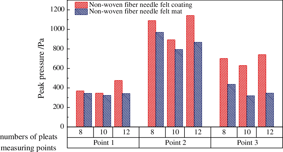
Figure 5: Variation of peak pressure on the side wall of pleated filter bags with different filter media
3.2 Numerical Results and Discussion
3.2.1 Flow Field Distribution of Bag Chamber with Different Pleats
Fig. 6 shows the velocity and static pressure distribution cloud diagram of different pleats in the bag chamber at t = 20 ms. Fig. 6a indicates that in the process of blowing pulse airflow into the filter bag from the nozzle, the airflow velocity is relatively large in the upper part of the filter bag but small in the bottom, and the airflow expansion is significant in the middle part. At the same time, the expansion area in the bag with N = 10 is the largest and the injection airflow is the closest to the bottom of the bag. However, Fig. 6b shows that the pulse cleaning energy distribution is uneven, which easily leading to poor dust cleaning and incomplete dust cleaning; The energy of dust cleaning in the middle and lower parts is large, easily leading to excessive dust cleaning and damage of filter bags, while the static pressure distribution in bags with N = 8 and 12 is relatively uniform, which is beneficial to dust cleaning.

Figure 6: Flow field distribution of filter bags with different pleats at t = 20 ms. (a) Cloud diagram of velocity distribution in filter bag with different pleats (b) Cloud diagram of static pressure distribution in filter bags with different pleats
3.2.2 Transient Dynamic Analysis of Filter Bags with Different Pleats
Fig. 7 shows the time variation of maximum acceleration of filter bags with different pleats. It can be seen that at the initial stage of injection, the maximum acceleration of the three groups of pleated filter bags reaches the maximum value when t = 2 ms, and presents a steady fluctuation trend when it is 20–200 ms. The maximum acceleration of the three groups of pleated filter bags is located at the top of the bags, which is caused by several times of ambient air induced by the high-speed airflow. This leads to the acceleration variation of other components to achieve dust cleaning effect, and the top of the filter bag is more easily damaged. In the process of pulse dust cleaning, the maximum acceleration of the filter bag directly reflects the impact strength of the filter bag under the action of pulse and represents the dust cleaning ability of the filter bag. The instantaneous maximum accelerations of filter bags with pleats N = 8, 10 and 12 are 252.93 m·s−2, 212.78 m·s−2 and 171.13 m·s−2, respectively. But at the same time, the maximum accelerations of the filter bag with N = 12 is more obvious than that of the other two groups. Generally speaking, the filter bags with N = 8 and 12 have better dust cleaning effect, which is the consistent with the conclusion of peak pressure analysis of pleat filter bags with different pleats in the Section 3.1 and 3.2. Because the maximum acceleration value is positively correlated with the maximum pressure rising rate, the filter bag with N = 12 reaches the peak pressure of the side wall quickly under the same injection pressure, and the dust removal effect is better.
Fig. 8 describes the maximum acceleration response curves of circular filter bags with different mechanical material parameters in [44,45], where the superscripts of a and b show two filter materials of Polyimide fiber (P84) with the same thickness and density, but different elastic modulus and Poisson’s ratio. Because of the different working conditions, filter bag structure and materials, there are some differences between the simulation results in this study, but both of them show a trend of first fluctuating and then stabilizing. Therefore, the simulation results of maximum acceleration in this study can be considered as correct.
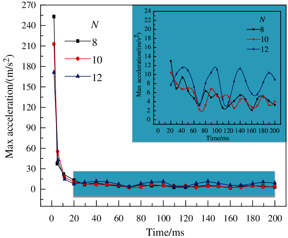
Figure 7: Maximum acceleration response curves of filter bags with different pleats
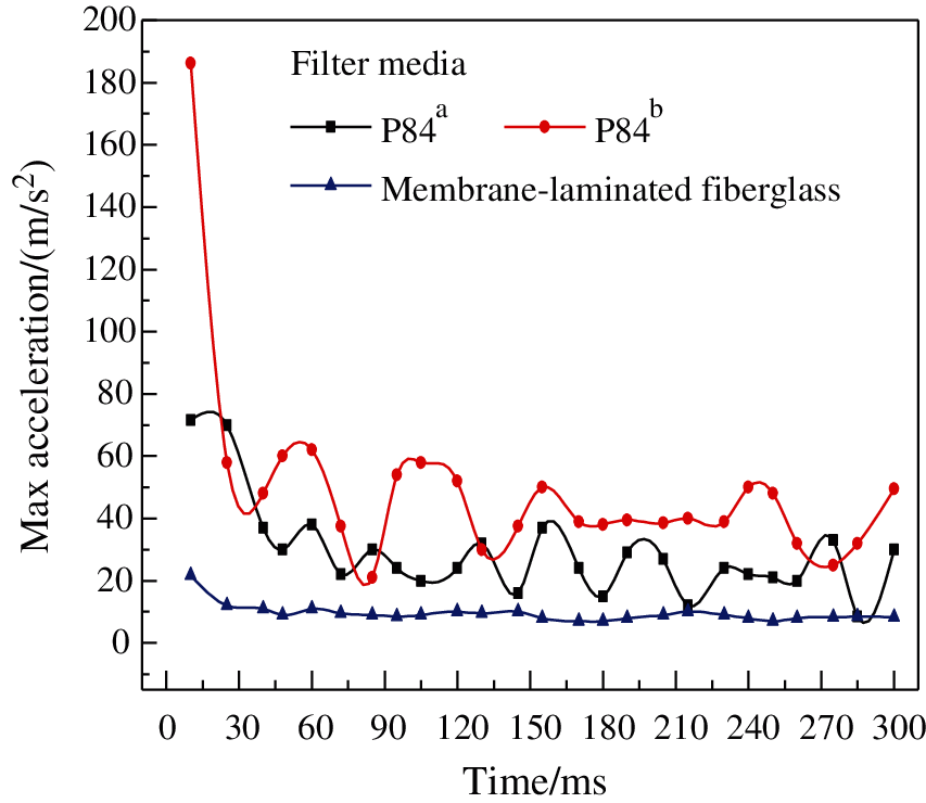
Figure 8: Maximum acceleration response curve of round filter bag with different mechanical material parameters
Fig. 9 shows the instantaneous maximum deformation cloud diagram and maximum deformation response curve of different pleated filter bags. As shown in Fig. 9a, the wall deformation of the three groups of filter bags is similar. Due to the pulsed-jet air flows from top to bottom in the filter bag with a restricted jet, and the friction and energy consumption between the airflow and the surface of the filter bag surface, which makes the shape variable of the filter bag gradually decrease along the bag length. Table 3 shows the maximum deformation and acceleration of three groups of filter bags with different folds. It can be seen from the table that under the same injection pressure, the maximum deformation of the filter bag with N = 8 is taken as the benchmark, the maximum deformation with N = 10 is reduced by 20%, and that with N = 12 is increased by 90%. So, the deformation amount of N = 12 is the largest, and that of N = 10 is the smallest. The force generated by deformation of objects is elastic force. The greater the elasticity, the better the dust cleaning effect. Therefore, the dust cleaning effect of N = 12 is better than that of N = 8 and 10.
And Fig. 9b can also draw this conclusion. In a certain injection interval, since the filter bags are in the state of “expansion→contraction” repeatedly, the maximum deformation of the walls of the three groups of filter bags increases periodically and then decreases. The maximum deformation time of the three groups of filter bags is 12.70, 163.5 and 13.64 ms, respectively. Obviously, the maximum deformation time of the filter bag with N = 12 is relatively quickly, which indicates that the filter bag is easier to cleaning dust. In general, the filter bag with N = 12 has the largest deformation and the maximum deformation time is relatively fast, which indicates that the filter bag is easier to clean, that is, the dust cleaning force is smaller than that with N = 8 and 10. The variation trend of the simulation curve in this study is basically consistent with the maximum deformation response curve of circular filter bags with different mechanical material parameters in [44] (shown in Fig. 9c).
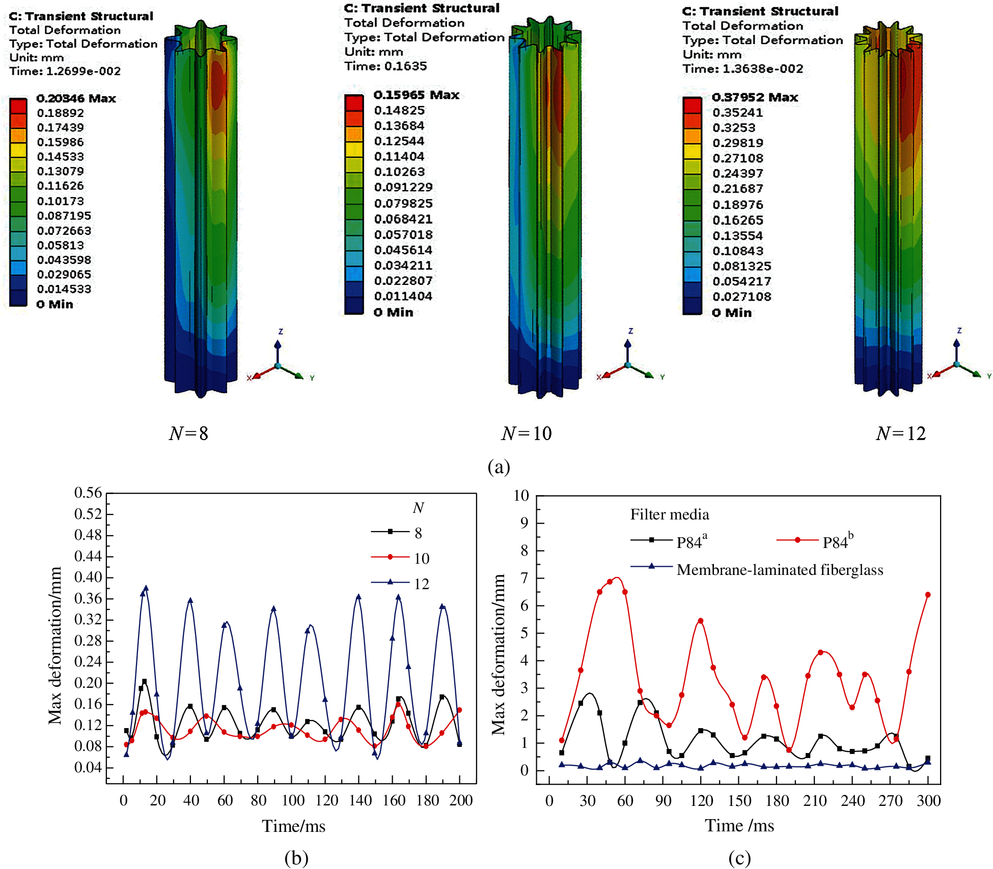
Figure 9: Instantaneous maximum deformation cloud and maximum deformation response diagram of filter bags with different pleats. (a) The instantaneous maximum deformation cloud of the filter bag with different pleats (b) Maximum deformation response curves of filter bags with different pleats (c) Maximum deformation response curves of filter bags with different mechanical material parameters
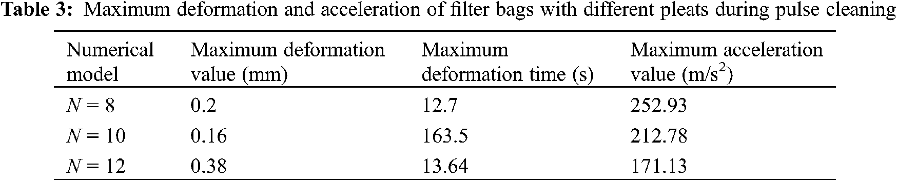
Fig. 10 displays the instantaneous maximum strain and stress response of filter bags with different folds. As is known, the filter bag will be destroyed once the limited stress increase is exceeded. Fig. 10a shows that the instantaneous maximum strain of the three groups of filter bags is 0.1384%, 0.1239% and 0.0977%, respectively, indicating that the fatigue damage of the filter bags with N = 8 and 10 is relatively serious, and the maximum strain is located at the edge of the bag mouth. Furthermore, it is also can be seen that the vibration intensity of the strain N = 8 and 12 in the filter bags is stronger than that of N = 10. Fig. 10b shows the maximum stress response diagram of filter bag with different folds, the maximum instantaneous stresses of the three groups of filter bags are 23.237, 19.960 and 16.643 kPa, respectively, which are all near the bag mouth, indicating that the dust bag mouth is easy to wear during actual operation. At the initial stage of pulsed-jet, the three groups of filter bags suffered the greatest impact and the stress changed greatly. Then the maximum stress tended to be stable in 20–200 ms.
In conclusion, the filter bags with N = 8 and 10 are seriously damaged by fatigue, and the filter bags with N = 8 and 12 have better dust cleaning strength. Therefore, consideration the stress-strain analysis comprehensively, the filter bag with N = 12 has the best overall dust removal effect.
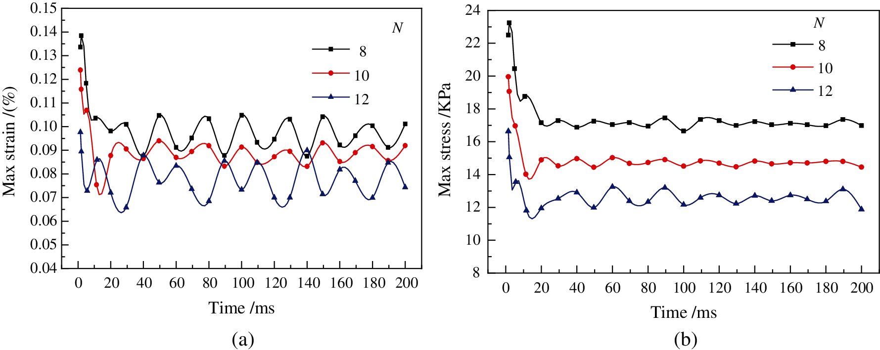
Figure 10: Instantaneous maximum strain and stress response curves of filter bags with different pleats. (a) Maximum strain response curve (b) Maximum stress response curve
In this study, the variations of the peak pressure on the six groups non-woven needle felt filter bag with and without film coating filter material N = 8, 10 and 12 were analyzed experimentally through the low-pressure pulsed-jet cleaning experiment. The flow structure and the law of acceleration, deformation, strain and stress of pleated filter bags in the low-pressure pulsed-jet cleaning process have been analyzed numerically through a computational fluid-dynamics/computational structural dynamics (CFD-CSD) unidirectional fluid-solid coupling method. Several conclusions can be drawn as follows:
(1) As shown by the experiments, the peak pressure (P0) on the wall of the filter bag with N = 8 and 12 is higher, which indicates dust can be removed more effectively in these cases. The peak pressure on the wall increases first and then decreases along the direction of the bag length, it is mainly affected by the pleat number at p2. For the peak pressure of the filter bags with non-woven needled felt film coating is greater than that without film coating.
(2) The simulation studies have found that N = 8 and 12 of the filter bags are believed more uniform and easier to dust cleaning by the simulations of bag indoor flow structure and filter bag transient kinetics. As the filter bag with N = 10 has the largest expansion area and the injection air flow is closest to the bottom of the bag, the lower pressure in the middle and upper part is easy to cause poor dust cleaning, and the high dust cleaning energy in the middle and lower parts leads to excessive dust cleaning.
(3) The comprehensive analysis of the time variation of acceleration, deformation, strain, stress and other factors, has led to the conclusion that the pleated filter bag with N = 12 would be the optimal choice: firstly, the overall level of maximum acceleration of N = 12 filter bag is the highest. Secondly, the maximum deformation of filter bag with N = 12 appeared quickly during the whole injection time. Thirdly, the maximum strain of filter bag with N = 12 is smaller, and the fatigue damage is not serious. Finally, the filter bag with N = 12 also have better dust cleaning strength.
Funding Statement: This study was financially supported by Anhui Provincial Scientific and Technological Major Project (Grant No. 18030801109).
Conflicts of Interest: The authors declare that they have no conflicts of interest to report regarding the present study.
1. Boudhan, R., Joubert, A., Durécu, S., Gueraoui, K., Le Coq, L. (2019). Influence of air humidity on particle filtration performance of a pulse-jet bag filter. Journal of Aerosol Science, 130, 1–9. DOI 10.1016/j.jaerosci.2019.01.002. [Google Scholar] [CrossRef]
2. Hua, Y., Nie, W., Liu, Q., Peng, H., Wei, W. et al. (2020). The development and application of a novel multi-radial-vortex-based ventilation system for dust removal in a fully mechanized tunnelling face. Tunnelling and Underground Space Technology, 98(5), 103253. DOI 10.1016/j.tust.2019.103253. [Google Scholar] [CrossRef]
3. Liu, Q., Nie, W., Hua, Y., Peng, H., Liu, C. et al. (2019). Research on tunnel ventilation systems: Dust diffusion and pollution behaviour by air curtains based on CFD technology and field measurement. Building and Environment, 147(21), 444–460. DOI 10.1016/j.buildenv.2018.08.061. [Google Scholar] [CrossRef]
4. Jiang, J., Ye, B., Xie, D., Li, J., Miao, L. et al. (2017). Sector decomposition of China’s national economic carbon emissions and its policy implication for national ETS development. Renewable and Sustainable Energy Reviews, 75(6098), 855–867. DOI 10.1016/j.rser.2016.11.066. [Google Scholar] [CrossRef]
5. Du, R., Shu, G., Wen, F. (2020). Analysis on schemes for ultra-low emission retrofitting of ore coke through dedusting in steel enterprise. Building Energy Environment, 39(01), 105–108. [Google Scholar]
6. Zhang, B., Zhao, B., Wang, Z. (2019). Application of high-efficiency filter bag in charging dedusting. Fuel & Chemical Processes, 50(6), 25–29. [Google Scholar]
7. Heinsohn, R. J. (1991). Industrial ventilation: Engineering principles. University of Texas Press. [Google Scholar]
8. Qian, Y., Bi, Y., Zhang, Q., Chen, H. (2014). The optimized relationship between jet distance and nozzle diameter of a pulse-jet cartridge filter. Powder Technology, 266, 191–195. DOI 10.1016/j.powtec.2014.06.004. [Google Scholar] [CrossRef]
9. Li, J., Li, S., Zhou, F. (2015). Effect of cone installation in a pleated filter cartridge during pulse-jet cleaning. Powder Technology, 284, 245–252. DOI 10.1016/j.powtec.2015.06.071. [Google Scholar] [CrossRef]
10. Rogoziński, T. (2018). Pilot-scale study on the influence of wood dust type on pressure drop during filtration in a pulse-jet baghouse. Process Safety and Environmental Protection, 119(5), 58–64. DOI 10.1016/j.psep.2018.07.016. [Google Scholar] [CrossRef]
11. Li, S., Jin, H., Hu, S., Tan, X., Liu, H. et al. (2019). Effect of novel built-in rotator on the performance of pleated cartridge filter. Powder Technology, 356, 1001–1007. DOI 10.1016/j.powtec.2019.08.052. [Google Scholar] [CrossRef]
12. Leo, R., Amorim, L. S., Martins, M. F., Junior, H. B., Mesquita, A. (2021). Airborne flow dynamics near free-falling bulk materials: CFD analysis from analytical pressure field. Powder Technology, 385(7), 1–11. [Google Scholar]
13. Chen, S., Chen, D. R. (2017). Annular-slit nozzles for reverse flow cleaning of pleated filter cartridges. Separation and Purification Technology, 177, 182–191. DOI 10.1016/j.seppur.2016.10.050. [Google Scholar] [CrossRef]
14. Li, S., Hu, S., Xie, B., Jin, H., Xin, J. et al. (2019). Influence of pleat geometry on the filtration and cleaning characteristics of filter media. Separation and Purification Technology, 210, 38–47. DOI 10.1016/j.seppur.2018.05.002. [Google Scholar] [CrossRef]
15. Lu, H. C., Tsai, C. J. (2003). Influence of different cleaning conditions on cleaning performance of pilot-scale pulse-jet baghouse. Journal of Environmental Engineering, 129(9), 811–818. DOI 10.1061/(ASCE)0733-9372(2003)129:9(811). [Google Scholar] [CrossRef]
16. Xie, B., Li, S., Chu, W., Liu, C., Hu, S. et al. (2020). Improving filtration and pulse-jet cleaning performance of metal web filter media by coating with polytetrafluoroethylene microporous membrane. Process Safety and Environmental Protection, 136(11), 105–114. DOI 10.1016/j.psep.2020.01.002. [Google Scholar] [CrossRef]
17. Allam, S., Elsaid, A. M. (2020). Parametric study on vehicle fuel economy and optimization criteria of the pleated air filter designs to improve the performance of an IC diesel engine: Experimental and CFD approaches. Separation and Purification Technology, 241, 116680. [Google Scholar]
18. Ou, Q., Maricq, M. M., Pui, D. Y. H. (2017). Evaluation of metallic filter media for sub-micrometer soot particle removal at elevated temperature. Aerosol Science and Technology, 51(11), 1303–1312. DOI 10.1080/02786826.2017.1349871. [Google Scholar] [CrossRef]
19. Çankaya, N., Özcan, M. (2019). Performance optimization and improvement of dust laden air by dynamic control method for jet pulsed filters. Advanced Powder Technology, 30(7), 1366–1377. DOI 10.1016/j.apt.2019.04.014. [Google Scholar] [CrossRef]
20. Chen, S., Gong, Y. (2019). Numerical study of the effects of cartridge shape on the reverse pulsed flow cleaning of pleated cartridge filters. Proceedings of the Institution of Mechanical Engineers, Part E: Journal of Process Mechanical Engineering, 233(2), 371–383. DOI 10.1177/0954408918787096. [Google Scholar] [CrossRef]
21. Chen, S., Chen, D. R. (2017). Cleaning of filter cartridges with convergent trapezoidal pleat shape via reverse multi-pulsing jet flow. Aerosol and Air Quality Research, 17(11), 2659–2668. DOI 10.4209/aaqr.2016.12.0539. [Google Scholar] [CrossRef]
22. Chen, S., Wang, Q., Chen, D. R. (2017). Effect of pleat shape on reverse pulsed-jet cleaning of filter cartridges. Powder Technology, 305(4), 1–11. DOI 10.1016/j.powtec.2016.09.013. [Google Scholar] [CrossRef]
23. Li, Q., Zhang, M., Qian, Y., Geng, F., Song, J. et al. (2015). The relationship between peak pressure and residual dust of a pulse-jet cartridge filter. Powder Technology, 283, 302–307. DOI 10.1016/j.powtec.2015.05.038. [Google Scholar] [CrossRef]
24. Rocha, S. M. S., Marques, F. B., Pereira, F. A. R., Ribeiro, D. C. (2014). Applications of CFD techniques in the design of fabric filters. Chemical Engineering Transactions, 39, 1369–1374. [Google Scholar]
25. Andersen, B. O., Nielsen, N. F., Walther, J. H. (2016). Numerical and experimental study of pulse-jet cleaning in fabric filters. Powder Technology, 291(12), 284–298. DOI 10.1016/j.powtec.2015.12.028. [Google Scholar] [CrossRef]
26. Park, S., Joe, Y. H., Shim, J., Park, H., Shin, W. G. (2019). Non-uniform filtration velocity of process gas passing through a long bag filter. Journal of Hazardous Materials, 365(1–3), 440–447. DOI 10.1016/j.jhazmat.2018.10.098. [Google Scholar] [CrossRef]
27. Qiu, J., Wu, D., Chen, D. R., Li, J. (2021). Reverse pulsed-flow cleaning of pleated filter cartridges having an inner pleated filter cone. Process Safety and Environmental Protection, 146, 481–489. DOI 10.1016/j.psep.2020.11.025. [Google Scholar] [CrossRef]
28. Jin, H., Hu, S., Xie, B., Yan, Y., Yang, M. et al. (2021). Experimental optimization for cleaning parameters and field application of cartridge filter in bulk grain loading. Powder Technology, 378, 421–429. DOI 10.1016/j.powtec.2020.10.003. [Google Scholar] [CrossRef]
29. Simon, X., Chazelet, S., Thomas, D., Bémer, D., Régnier, R. (2007). Experimental study of pulse-jet cleaning of bag filters supported by rigid rings. Powder Technology, 172(2), 67–81. DOI 10.1016/j.powtec.2006.10.005. [Google Scholar] [CrossRef]
30. Humphries, W., Madden, J. J. (1983). Fabric filtration for coal-fired boilers: dust dislodgement in pulse jet filters. Filtration & Separation, 20(1), 40–42. [Google Scholar]
31. Li, X., Chambers, A. J. (1995). Model of dust collection and removal from mechanically shaken filter bags. Filtration & Separation, 32(9), 891–895. DOI 10.1016/S0015-1882(97)84174-2. [Google Scholar] [CrossRef]
32. Chen, L., Ye, M., Liu, Z., Qian, F., Wei, M. et al. (2020). Experimental investigation on low-pressure pulse dust cleaning performance of plate-frame microporous membrane filter media. Powder Technology, 375, 352–359. DOI 10.1016/j.powtec.2020.08.003. [Google Scholar] [CrossRef]
33. Paik, K. J., Carrica, P. M. (2014). Fluid-structure interaction for an elastic structure interacting with free surface in a rolling tank. Ocean Engineering, 84, 201–212. DOI 10.1016/j.oceaneng.2014.04.016. [Google Scholar] [CrossRef]
34. Jaiman, R., Geubelle, P., Loth, E., Jiao, X. (2011). Combined interface boundary condition method for unsteady fluid-structure interaction. Computer Methods in Applied Mechanics and Engineering, 200(1–4), 27–39. DOI 10.1016/j.cma.2010.06.039. [Google Scholar] [CrossRef]
35. Kim, J. U., Hwang, J., Choi, H. J., Lee, M. H. (2017). Effective filtration area of a pleated filter bag in a pulse-jet bag house. Powder Technology, 311, 522–527. DOI 10.1016/j.powtec.2017.02.013. [Google Scholar] [CrossRef]
36. Chen, D., Pui, D. Y. H., Liu, B. Y. H. (2007). Optimization of pleated filter designs using a finite-element numerical model. Aerosol Science and Technology, 23(4), 579–590. DOI 10.1080/02786829508965339. [Google Scholar] [CrossRef]
37. Menter, F. R., Kuntz, M., Langtry, R. (2003). Ten years of industrial experience with the SST turbulence model. Heat and Mass Transfer, 4, 1–8. [Google Scholar]
38. Dai, Z., Li, T., Zhang, W., Zhang, J. (2020). Numerical study on aerodynamic performance of high-speed pantograph with double strips. Fluid Dynamics & Materials Processing, 16(1), 31–40. DOI 10.32604/fdmp.2020.07661. [Google Scholar] [CrossRef]
39. Li, G. (2020). Simulation of the thermal environment and velocity distribution in a lecture hall. Fluid Dynamics & Materials Processing, 16(3), 549–559. DOI 10.32604/fdmp.2020.09219. [Google Scholar] [CrossRef]
40. Lo, L. M., Hu, S. C., Chen, D. R., Pui, D. Y. H. (2010). Numerical study of pleated fabric cartridges during pulse-jet cleaning. Powder Technology, 198(1), 75–81. DOI 10.1016/j.powtec.2009.10.017. [Google Scholar] [CrossRef]
41. Mehdipour, H., Camanho, P. P., Belingardi, G. (2019). Elasto-plastic constitutive equations for short fiber reinforced polymers. Composites Part B: Engineering, 165(12), 199–214. DOI 10.1016/j.compositesb.2018.11.106. [Google Scholar] [CrossRef]
42. Scutaru, M. L., Chircan, E., Marin, M., Grif, H. Ş. (2020). Liaison forces eliminating and assembling of the motion equation in the study of multibody system with elastic elements. Procedia Manufacturing, 46(7), 78–86. DOI 10.1016/j.promfg.2020.03.013. [Google Scholar] [CrossRef]
43. Pei, C., Ou, Q., Yu, T., Pui, D. Y. H. (2019). Loading characteristics of nanofiber coated air intake filter media by potassium chloride, ammonium sulfate, and ammonium nitrate fine particles and the comparison with conventional cellulose filter media. Separation and Purification Technology, 228(6), 115734. DOI 10.1016/j.seppur.2019.115734. [Google Scholar] [CrossRef]
44. Wang, Y. (2011). The research on the pulse cleaning of the bag filter with unsteady numerical simulation and performance optimization. Nanchang University. [Google Scholar]
45. Tang, H. (2009). Experimental research on pulse cleaning installation of baghouse filter. Donghua University. [Google Scholar]
 | This work is licensed under a Creative Commons Attribution 4.0 International License, which permits unrestricted use, distribution, and reproduction in any medium, provided the original work is properly cited. |