Materials Processing
| Fluid Dynamics & Materials Processing |
DOI: 10.32604/fdmp.2021.015429
ARTICLE
Influence of the Hook Position on the Vertical Vibrations of an Automobile Exhaust System: Application of the Robust Optimization Design
Xinyu Key Laboratory of Materials Technology and Application for Intelligent Manufacturing, Xinyu University, Xinyu, China
*Corresponding Author: Jianqiang Xiong. Email: xiongjianqiang@xyc.edu.cn
Received: 17 December 2020; Accepted: 01 March 2021
Abstract: A robust optimization design method is proposed to investigate the influence of the hook position on the vertical vibration (bending) of an automobile exhaust system. A block diagram for the robustness analysis of the exhaust system is initially constructed from the major affecting factors. Secondly, the second-order inertia force is set as the vibration excitation source of the exhaust system and the displacement of four hooks of the exhaust system is selected as the variable factor. Then tests are carried out to investigate the resulting vertical bending considering four influencing factors and three levels of analysis. Finally, a variance analysis of the vertical bending is performed. The present study provides a set of guidelines to control the key factors affecting the vibration of vehicle exhaust systems while proposing an effective method to reduce vehicle vibration and improve noise analysis.
Keywords: Robust optimization design; exhaust system; modal analysis; excitation source
The performance of the engine exhaust system not only affects the pumping loss and exhaust emissions but also causes vibration and noise. One end of the exhaust system is connected with the engine, and the other is connected with the vehicle body through a hook. The excitation source transmits the vibration to the exhaust system through the connector, and the vibration is transmitted to the automobile body floor through the hook of the exhaust system. Then, the vibration of the bottom plate is directly transmitted to the passengers through the seat, steering wheel and floor. Meanwhile, the vibration of the vehicle body radiates in the form of noise that causes noise in the car. The automobile exhaust system is an essential environmental protection system that purifies the automobile exhaust, reduces the exhaust vibration and noise, and meets the relevant emission and noise regulations. Moreover, the vibration and noise directly transmitted to the interior of the vehicle through the exhaust system are one of the major factors affecting automobile riding comfort. Therefore, the vibration of the exhaust system is one of the major research topics in automotive NVH (Noise, Vibration, Harshness).
At present, there are few quantitative studies regarding factors affecting automobile vibration. Moreover, the quantitative analysis of the factors affecting the vibration of the exhaust system is even less. Before the vibration control of the exhaust system, it is not enough to understand the contribution degree of each influencing factor to the vibration of the exhaust system only through qualitative research. Because the contribution data of each influencing factor cannot be obtained through research, only judging from the influence degree, there is the possibility of missing the key influencing factors. Consequently, it is necessary to find out the accurate data of each influencing factor’s contribution to the vibration of the exhaust system through quantitative research, in order to avoid missing the key factors of vibration influence and formulate reasonable and feasible measures for the vibration control of the exhaust system. Therefore, in the present study, a robust optimization design method is proposed and a quantitative study of the influence of the hook position movement on the vertical bending vibration of the automobile exhaust system is carried out. In this study, the displacement of the hook position is considered as the main object of the vibration analysis and research of the exhaust system. Moreover, the other secondary factors are ignored, and the second-order inertia force of the engine is used as the excitation source of the exhaust system vibration. The relevant factors affecting the vibration of the exhaust system are investigated to provide a reliable basis for the vibration control of the exhaust system. The proposed method is expected to expand the research of automobile vibration, noise and comfort. Moreover, it is an effective method in improving the accuracy, rationality and effectiveness of automobile vibration and noise control methods.
Many researchers have carried out relevant research. Zhang et al. [1] designed and adjusted the hook position of the automobile exhaust system. After the adjustment, the exhaust system was subjected to more uniform forces, avoiding the engine idle excitation frequency from the engine exhaust manifold to the exhaust tailpipe, and also reducing the dynamic reaction force transmitted to the car body. Long et al. [2] used the response surface method to optimize the stiffness of lugs, which significantly reduced the dynamic load transferred by the lugs. Through sensitivity analysis, Songbo et al. [3] concluded that the length and stiffness of bellows have a big effect on the natural frequency distribution of the exhaust system, and the low-frequency natural frequency is more sensitive to the lug stiffness. Moreover, Eads et al. [4] analyzed the vibration, noise, fatigue, emission, vibration transfer function, sensitivity and mechanical behavior of the exhaust system. Goktan et al. [5] established a semi-car model with an exhaust system and studied the transmission characteristics of the pavement spectrum excitation vibration. Ling et al. [6] discretized the exhaust system by using beam elements. They simulated the powertrain excitation with the sinusoidal displacement at the front end of the exhaust pipe, while the powertrain sub-model was not considered. Therefore, the dynamic stiffness was optimized with the hook dynamic load. Lee et al. [7] studied the dynamic stiffness of hook. They found that the stiffness should not be too high; otherwise it is not conducive to the hook vibration isolation. Meanwhile, the dynamic stiffness of the hook should not be too low, otherwise, the vibration isolation frequency will be increased and the hook will produce large static deformation. Rao et al. [8] studied the dynamic characteristics of the exhaust system hook and their position arrangement. Butkewitsch et al. [9] optimized the muffler support for the exhaust pipe front of a commercial automobile by using the substructure method and improved the stiffness by modifying the size of the support to adjust the natural frequency of the exhaust system and avoid coupling with the powertrain excitation. Arunpreya et al. [10] studied the impact of the sound design of bellows on the vibration isolation and fatigue life improvement of exhaust systems. Seldon et al. [11] carried out a simplified numerical simulation study on the bellows, established a detailed modal of the exhaust system, and determined the suspension point layout scheme of the exhaust system. Tian et al. [12] Used robustness method to optimize the inlet diameter, inlet width, blade number and blade angle of centrifugal pump, the test results under different parameters and the optimization model are obtained. Based on the robust optimization method, Cheng et al. [13] optimized the parameters of the distributed heating hybrid energy system. Through the experimental parameter optimization, a more convenient and efficient design parameter combination was obtained. Gu et al. [14] conducted the numerical simulation and optimized the design of the exhaust system. Moreover, they found the main reason for the backpressure of the exhaust system and proposed corresponding improvement measurements. Pang et al. [15] established the vibration equation of the exhaust system, optimized the objective function as the vibration characteristic of the exhaust system, and took the stiffness of the bellow in each direction as the design variable. They concluded that the axial stiffness of the bellow was the most important factor affecting the vibration transmission of the exhaust system. Iyer et al. [16] compared the finite element analysis mode with the experimental analysis mode to obtain the influence trend of the specific frequency band on the natural frequency. Xiong et al. [17] utilized the robustness analysis method to study the vehicle suspension system. Through the analysis of the experimental data, the quantitative data of the contribution of the changes of suspension damping and stiffness to the vibration of the suspension system were obtained. Baringo et al. [18] analyzed the advantages, disadvantages and application of the robust optimization design. Benadda et al. [19] used the robust optimization method to establish the frequency optimization model of the vehicle mounting system, which improved the frequency characteristics of the system. Lee et al. [20] used the Taguchi method to optimize the parameters of a permanent magnet motor. Sorgdrager et al. [21] used the robust optimization design to optimize the parameters of the thermal power generation system and obtained the sensitivity data of the key factors affecting the thermal power generation system. Borboni et al. [22] used a robust optimization design to study the shape memory actuator and obtained the optimal combination data of each parameter. Guesmi et al. [23] used the improved genetic algorithm to optimize the robustness of the multi-motor power system, obtained the optimized parameter combination, and proved the effectiveness and correctness of the method through experiments.
3 Vibration Robustness Analysis of the Exhaust System
Automobile vibration robustness is defined as vibrations in the process of design, development and operation of automobiles, and the influence of the structure and operating environment on the vibration quality. It is worth noting that the key influencing factors of the vibration can be obtained through the robustness analysis of various influencing factors of the automobile vibration, and the influencing factors can be optimized accordingly. This is called the robustness analysis method.
3.1 Influence of the Hook Position Movement on the Exhaust System Vibration
Theoretically, the reasonable location of the hook can be determined through finite element analysis to achieve the optimal modal frequency of the exhaust system. However, considering the influence of various interference factors in real applications, the optimal position of the hook may change. In this case, it is necessary to study the hook position movement, which has the greatest impact on the modal frequency of the exhaust system. Moreover, the hook position movement should be analyzed to determine the best hook position. Further investigations reveal that many index factors should be considered in the modal analysis of the exhaust system. Tab. 1 presents the main performance indices of the modal analysis.
Table 1: Key performance indices of the exhaust system modal analysis
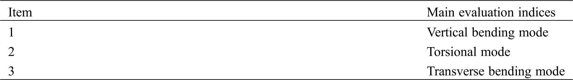
Among the key performance indicators of the exhaust system modal analysis in Tab. 1, the vertical bending mode can be simply excited and strengthened by external factors. Moreover, it is most prone to generate a resonance mode, while torsional and transverse bending modes are hardly easily excited by external factors. Therefore, in this study, the influence of the hook position movement on the vertical bending modal frequency of the exhaust system is studied and the most influential factor of the hook position movement is obtained. Accordingly, a reliable basis is obtained for the vibration control of the exhaust system.
3.2 Model Diagram for the Robustness Analysis of the Exhaust System
The detailed process of establishing the vibration robustness analysis model is as follows:
1. Define the research object of the model diagram construction. In this study, the research object is the automobile exhaust system.
2. Analyze the influencing factors of the exhaust system vibration and identify the influencing factors of the exhaust system vibration.
3. Classify the controllable and uncontrollable influencing factors of the exhaust system vibration. The fluctuation of controllable factors can be controlled by the designer in the vibration target analysis object. In the vibration analysis of the exhaust system, the stiffness of the hook, vibration isolator and flexible connecting pipe are controllable factors. The uncontrollable factors are difficult to determine in the vibration target analysis object and cannot be controlled by the designer. The hook position is an uncontrollable factor in the vibration analysis of the exhaust system.
4. Identify the vibration excitation source of the exhaust system. In this study, the second-order inertia force is used as the vibration excitation source of the exhaust system, and other excitation sources are ignored.
5. Define the output variables of the model. In the present study, the output variables are modal frequency and transfer force. Through the analysis of the parameters of these two variables, the quantitative results of the influence on the vibration of the exhaust system are obtained.
Therefore, Fig. 1 shows the vibration robustness analysis principle when the hook position moves.
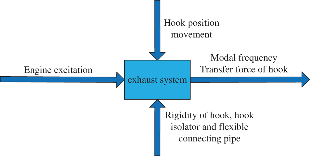
Figure 1: Model diagram for the robustness analysis of the exhaust system
Fig. 1 shows that the automobile engine is the original excitation input for the vibration analysis of the exhaust system. Theoretically, the stiffness of the hook, vibration isolator and flexible connecting pipe of the exhaust system are regarded as controllable factors. Moreover, in the vibration robustness analysis, the influence of the hook position movement as a noise factor on the vertical bending modal frequency of the exhaust system is studied.
3.3 Exhaust System Factors and Their Levels
Generally, there are four hooks in the exhaust system, and there is a certain deviation between the actual position of the exhaust system hook and the theoretical optimal position. Therefore, quantitative research is carried out to find out the actual optimal position combination of each hook. In order to carry out the quantitative analysis of the exhaust system vibration in a certain range, the hook should move 20 mm before and after the theoretical optimal position. The quantitative influence on the vertical bending modal frequency of the exhaust system is obtained by analyzing the displacement combination of the hook. Therefore, the existing position of each hook has an optimal theoretical position. Moreover, the theoretical optimal position moves backward by 20 mm, and the theoretical optimal position moves forward by 20 mm. Considering the specific situation, only one part of the parameters of the exhaust system is designed. Therefore, the combined data of four hook positions and several different parameters of the exhaust system can be obtained. Then, the data are analyzed by using the robust analysis method. Finally, the quantitative results of the influence of the hook position movement on the vertical bending frequency of the exhaust system are investigated.
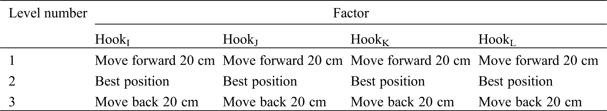
The abovementioned analysis shows that the vibration robustness analysis of the exhaust system under the condition of the hook position moving is a four-factor and three-level problem. In the present study, the mutual interference between factors is not considered. Tab. 2 presents the exhaust system factors and their levels.
Table 2: Exhaust system factors and their levels
3.4 Experimental Arrangement of the Vibration Robustness Design of the Exhaust System
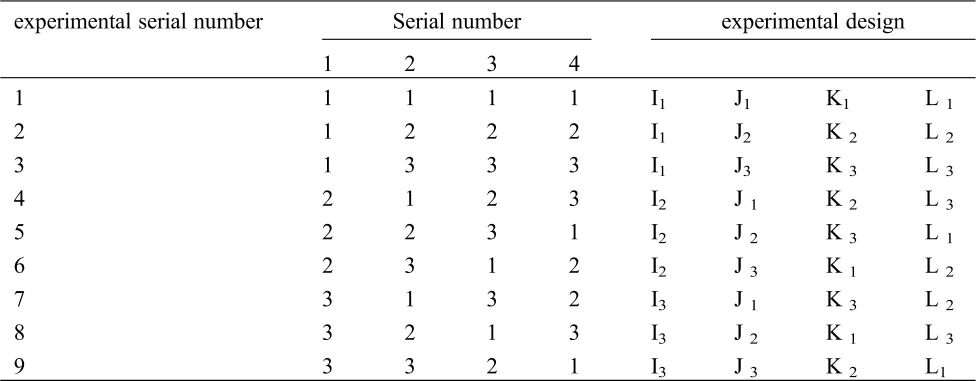
The robust method is an optimal design method of using an orthogonal array to arrange and analyze a variety of factors. A representative horizontal combination from all of the combinatorial tests is carried out. Through the experimental results, the overall test situation and the optimal design method of the level combination are obtained. It should be indicated that this method has strong orthogonality, representativeness and comprehensiveness.
Since mutual influence between the hook position movements is not considered, the orthogonal table
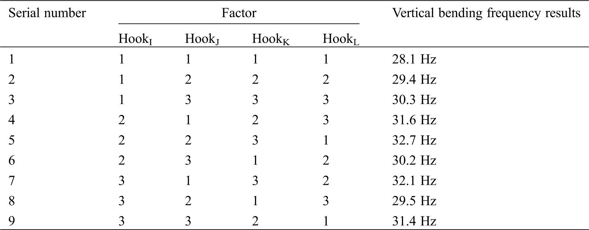
Table 3: Experimental arrangement of the vibration robustness design of the exhaust system
4 Vibration Excitation Source of the Exhaust System
Four major factors that affect the vibration of the exhaust system are as the following: 1) The engine connected with the exhaust system, and the mechanical vibration generated by the engine is directly transmitted to the exhaust system. 2) The vibration of the tire and vehicle body caused by road excitation results in the vibration of the exhaust system. 3) The vibration caused by the rapid airflow generated by engine combustion in the exhaust system pipe. 4) The hook is connected with the car body, which causes the vibration of the exhaust system when the automobile body vibrates. Considering the primary and secondary correlation of excitation sources and model building factors, only the vibration caused by the engine is analyzed. According to the cause and dynamic analysis of the engine excitation force, the second-order inertia excitation of the engine is mainly considered. The excitation model can be mathematically expressed as follows:
where P and λ denote the second reciprocating inertia force and the connecting rod ratio, respectively. Moreover, R and
Since the vibration energy of the vehicle is mainly concentrated in the frequency band of 20Hz–125Hz, the frequency spectrum of the second-order reciprocating inertia harmonic excitation with the engine speed between 800 r/min and 4000 R/min is analyzed by the Fourier transform. Then, Fig. 2 shows that it is converted into the frequency-domain excitation to obtain the excitation amplitude of the engine in 20 Hz–125 Hz frequency band.
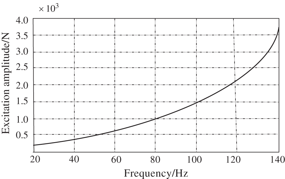
Figure 2: Second order reciprocating inertia excitation of engine
5 Analysis of the Experimental Results of the Displacement of the Hook Position in the Exhaust System
In order to investigate the influence of the hook position movement on the vertical bending vibration, the average response value of the level number of each hook position movement should be initially calculated and the corresponding response diagram should be drawn according to the average response value. According to the correlation diagram of the results between the hook position movement and the experimental design, the influence trend on the vertical bending vibration of the exhaust system can be obtained. Tab. 4 shows the intuitive analysis of the effect of the hook position movement on the vibration robustness of the exhaust system.
Table 4: Intuitive analysis of the exhaust system vibration
The calculation formula of the level sum of hookI is expressed as follows:
The level sum of hookI is as follows:
The level sum of other hooks is as follows:
The equation of the level mean value of hookI is as follows:
The level mean value of hookI is:
The level mean value of other hooks is as follows:
Considering the calculation of the level value and level sum mean value, the influence trend chart is drawn to show the concentration trend, fluctuation degree and distribution shape of the test data in the scheme. Therefore, the results of the influence of various factors on the vibration of the exhaust system are obtained.
According to the experimental results of each hook, the influence trend diagram of each factor can be drawn. x-coordinate and y-coordinate present the level value and the level sum mean value, respectively. Then, the coordinate points formed by each level value and level mean values are connected with approximate straight lines. Fig. 3 illustrates the vertical bending vibration response diagram of the exhaust system.
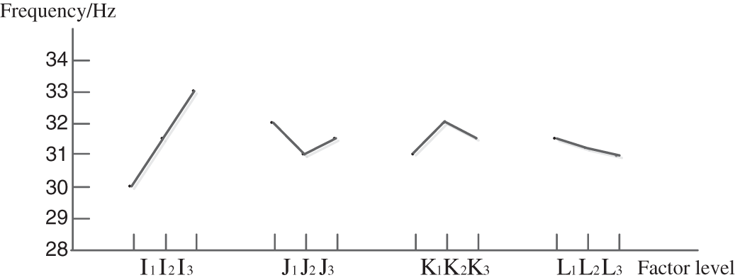
Figure 3: Vertical bending frequency response of the exhaust system
It is observed that different levels and level mean values of the same parameter reflect the trend of the influence on the vertical bending vibration of the exhaust system. Moreover, it is found that the movement of hookI and hookL has an obvious effect on the vertical bending vibration of the exhaust system, while hookJ and hookK do not have an obvious effect on the vertical bending vibration of the exhaust system.
The equation for calculating the range of affecting factors is as follows:
The range of hookI is calculated as follows:
The range of other hooks is calculated as follows:
According to the abovementioned equations, the ranges of the hooks in descending order are as follows:
It is worth noting that the smaller the hook range, the smaller the influence of the hook movement on the vertical bending modal of the exhaust system. Moreover, the greater the hook range, the greater the influence of the hook movement on the vertical bending mode of the exhaust system. Therefore, it is necessary to be quite careful when adjusting the hook position with a large range value; otherwise, the vibration will be strengthened. Therefore, the movement of hookK has the biggest impact on the vertical bending mode of the exhaust system, followed by hookI. On the other hand, the movement of hookJ has the least impact on the vertical bending vibration of the exhaust system, which means the best effect on the vertical bending vibration robustness of the exhaust system, followed by hookL. Therefore, the vibration robustness analysis under the condition of four hooks as uncontrollable factors shows that the position movement of hookK and hookI should be reduced as far as possible to improve the robustness of the vertical bending vibration of the exhaust system. However, the influence of hookJ and hookL position movement on the vertical bending vibration of the exhaust system can be ignored.
Considering the variance analysis of orthogonal experimental data of the hook position movement, the contribution rate and the primary and secondary correlation of the impact of hook position movement on the vertical bending vibration of the exhaust system can be obtained quantitatively and accurately. Therefore, in order to obtain an economical and practical design scheme, the key factors that affect the vibration should be adjusted and controlled appropriately, while the secondary factors should be ignored.
Total square sum can be calculated through the following expression:
In the abovementioned equation
The calculation equation of the total degree of freedom is as follows:
The total degree of freedom is calculated as follows:
The equation of single factor sum of square is as follows:
The single factor sum of square of hookI is calculated as follows:
The single factor sum of square of other hooks is calculated as follows:
Single-factor degrees f freedom are as follows:
where n refers to the number of levels with different values of influencing factors of the exhaust system vibration. In this study, the value of the level number is 3, so n = 3
The single factor degrees of freedom are calculated as follows:
Since there are no empty column items in the orthogonal experiment scheme, the sum of SJ of hookJ and SL of hookL, which has a smaller sum of square fluctuations of influencing factors in the orthogonal test, can be taken as Se. Moreover, the sum of fJ of hookJ and fL of hookL can be considered as error fluctuation square sum degree of freedom
Tab. 5 shows the analysis of variance, which is obtained according to the calculation data of the sum of square, degree of freedom and mean square in the experimental scheme of the hook position movement of the exhaust system.
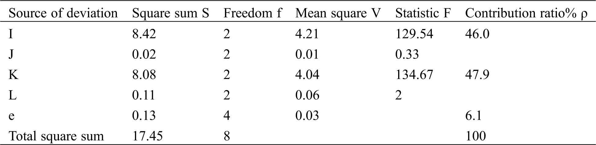
The Intuitive analysis gives the qualitative analysis of the influence of the hook position movement on the vertical bending mode of the exhaust system. On the other hand, the variance analysis gives the quantitative conclusion of the influence of the hook position movement on the vertical bending mode of the exhaust system, which provides an important judgment basis for the control of the noise factors under the hook position movement. Fig. 4 illustrates the contribution of the hook position movement to the vertical bending mode of the exhaust system.
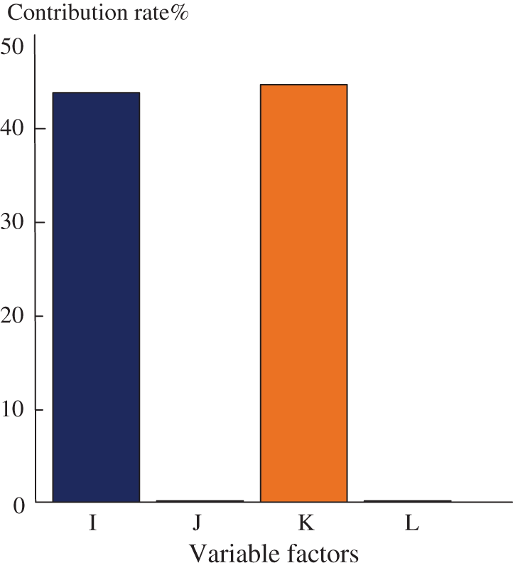
Figure 4: Vibration contribution of various factors
Fig. 4 shows that the position movements of hookI and hookK are the key affecting factors, and their impacts on the vertical bending mode of the exhaust system are 46.0% and 47.9%, respectively. However, in the case of hookJ and hookL moving, the influence on the vertical bending mode of the exhaust system is negligible. Therefore, among the four hook position movement factors, the key control factors affecting the vertical bending mode of the exhaust system are hookK and hookI. Moreover, the secondary factors are hookJ and hookL. Furthermore, the quantitative analysis conclusion of the influence of the hook position movement on the vertical vibration mode of the exhaust system is obtained, which provides an important design basis for the optimization of the hook position and the improvement of the vibration performance of the exhaust system.
In the present study, influencing factors of the exhaust system are investigated by the robust optimization design method. Based on the robust analysis of influencing factors of the exhaust system, this study investigates the vertical bending modal of the exhaust system with the hook position moving from qualitative and quantitative aspects. A schematic diagram for the robustness analysis of the vertical bending vibration of the exhaust system with four moving hook positions is constructed. The second-order inertia force of the engine is the excitation source of the exhaust system, and the four hook positions of the exhaust system are taken as variable factors. Moreover, using the
The robust optimization design is used to study the vertical bending vibration of the automobile exhaust system. Therefore, not only the qualitative results of the influence of the hook position movement on the vertical bending vibration modal of the exhaust system can be obtained, but also the quantitative data of the influence of the hook position movement on the vertical bending vibration of the exhaust system can be obtained. The proposed method is beneficial for the control of key factors of the vehicle exhaust system vibration. Moreover, it has a certain reference for the development of vehicle vibration and noise analysis methods. It is worth noting that when using the proposed method to study the related issues, attention must be paid to the analysis of the key influencing factors. Otherwise, omission problems occur in the process of the system robustness optimization, which will lead to a large error of the method analysis results and affect the accuracy of the analysis method conclusions. The level number of influencing factors should be determined according to the actual situation. Too many levels lead to an increase in the number of experiments, which will lead to an increase in the calculation amount of the method. On the other hand, too few levels lead to the unreliability of the experimental data. In the follow-up study of the method, the complexity, time-consuming level and related software system development of the method should be considered to improve the applicability of the method and improve the efficiency and convenience of the algorithm.
Acknowledgement: The authors would like to thank the anonymous reviewers for the helpful suggestion.
Funding Statement: This research was funded by science and technology projects of Jiangxi Provincial Education Department (GJJ161186).
Conflicts of Interest: The authors declare that they have no conflicts of interest to report regarding the present study.
1. Zhang, P., Song, X. L. (2012). Simulation research of vehicle exhaust system hanger location. Advanced Materials Research, 482-484, 347–353. DOI 10.4028/www.scientific.net/AMR.482-484.347. [Google Scholar] [CrossRef]
2. Long, J., Zhang, Y., Zhou, J., Zheng, J., Pang, J. (2018). The research on structural optimization of ATV exhaust system based on response surface method. Chinese Internal Combustion Engine Engineering, 39(4), 9–14. [Google Scholar]
3. Li, S. B., Jin, Y. J., Guan, X. A. (2008). A study on the effect of power train on exhaust system dynamics and the sensitivity analysis of exhaust system components. Automotive Engineering, 30(4), 322–325. [Google Scholar]
4. Eads, K., Haghighi, K., Kim, H., Grace, J. (2000). Finite element optimization of an exhaust system. SAE Technical Paper, 104(1), 117–125. [Google Scholar]
5. Goktan, A., Yetkin, A. (2001). A mathematical model for exhaust system vibrations caused by road surface inputs. SAE Technical Paper, 105(3), 6–15. [Google Scholar]
6. Ling, S. F., Pan, T. C., Lim, G. H., Tseng, C. H. (1994). Vibration isolation of exhaust pipe under vehicle chassis. International Journal of Vehicle Design, 15(1/2), 131–142. [Google Scholar]
7. Lee, C. M., Park, S. T., Kim, S. H. (1999). Development of a simple numerical method of the exhaust system to find optimized design values. SAE Technical Papers, 103(3), 921–930. [Google Scholar]
8. Rao, M. D., Wirkner, K. J., Gruenberg, S. (2005). Dynamic characterization of automotive exhaust isolators. Journal of Automobile Engineering, 218(8), 891–900. DOI 10.1243/0954407041581110. [Google Scholar] [CrossRef]
9. Butkewitsch, S., Steffen, V. (2001). Case study on frequency response optimization. International Journal of Solids and Structures, 38(10–13), 1737–1748. DOI 10.1016/S0020-7683(00)00133-5. [Google Scholar] [CrossRef]
10. Arunpreya, K., Soundararajan, S. (2012). A finite element methodology to design and validate the performance of an automotive exhaust system. SAE Technical Paper [Google Scholar]
11. Seldon, W., Shoeb, A., Schimmel, D., Cromas, J. (2017). Experimental GT-POWER correlation techniques and best practices low frequency acoustic modeling of the exhaust system of a naturally aspirated engine. SAE Technical Paper, 121(6), 1793–1801. [Google Scholar]
12. Tian, P., Huang, J., Shi, W., Zhou, L. (2019). Optimization of a centrifugal pump used as a turbine impeller by means of an orthogonal test approach. Fluid Dynamics & Materials Processing, 15(2), 139–151. DOI 10.32604/fdmp.2019.05216. [Google Scholar] [CrossRef]
13. Cheng, L., Guo, B., Li, K. (2021). Design and optimization of a hybrid energy system for decentralized heating. Fluid Dynamics & Materials Processing, 17(1), 49–70. [Google Scholar]
14. Gu, F., Liu, B., Pan, S. (2007). Numerical simulation and optimal design for automotive exhaust systems. Automotive Engineering, 29(11), 25–28. [Google Scholar]
15. Pang, J., Kurrle, P., Qatu, M., Rebandt, R., Malkowski, R. (2003). Attribute analysis and criteria for automotive exhaust systems. SAE Technical Paper, 107(5), 221–229. [Google Scholar]
16. Iyer, G., Mohan, S., Rao, N., Unnithan, S. (2013). Evaluation of dynamic characteristics of an automotive exhaust system using operational modal analysis (OMA) and experimental modal analysis (EMA). SAE Technical Paper, 117(11), 2903–2913. [Google Scholar]
17. Xiong, J. Q., Yuan, L. (2020). Quantitative research on contribution degree of vibration affecting factors of vehicle suspension system based on robustness analysis. International Journal of Ambient Computing and Intelligence, 11(1), 71–86. DOI 10.4018/IJACI.2020010104. [Google Scholar] [CrossRef]
18. Baringo, L., Conejo, A. J. (2011). Offering strategy via robust optimization. IEEE Transactions on PowerSystems, 26(3), 1418–1425. [Google Scholar]
19. Benadda, M., Bouamrane, K., Belalem, G. (2017). How to manage persons taken malaise at the steering wheel using haaas in a vehicular cloud computing environment. International Journal of Ambient Computing and Intelligence, 8(2), 70–87. DOI 10.4018/IJACI.2017040105. [Google Scholar] [CrossRef]
20. Lee, U., Park, S., Lee, I. (2020). Robust design optimization (rdo) of thermoelectric generator system using non-dominated sorting genetic algorithm II (nsga-II). Energy, 196(4.1), 117090.1–117090.14. [Google Scholar]
21. Sorgdrager, A. J., Wang, R., Grobler, A. (2018). Multi-objective design of a line-start PM motor using theTaguchi method. IEEE Transactions on Industry Applications, 54(5), 4167–4176. DOI 10.1109/TIA.2018.2834306. [Google Scholar] [CrossRef]
22. Borboni, A., Faglia, R. (2018). Robust design of a shape memory actuator with slider and slot layout and passive cooling control. Microsystem Technologies, 24(3), 1379–1389. DOI 10.1007/s00542-016-2998-9. [Google Scholar] [CrossRef]
23. Guesmi, T., Farah, A., Abdallah, H. H., Ouali, A. (2018). Robust design of multimachine power system stabilizers based on improved non-dominated sorting genetic algorithms. Electrical Engineering, 100(3), 1351–1363. DOI 10.1007/s00202-017-0589-0. [Google Scholar] [CrossRef]
 | This work is licensed under a Creative Commons Attribution 4.0 International License, which permits unrestricted use, distribution, and reproduction in any medium, provided the original work is properly cited. |