Materials Processing
| Fluid Dynamics & Materials Processing |
DOI: 10.32604/fdmp.2021.014902
ARTICLE
Numerical Investigation on the Secondary Flow Control by Using Splitters at Different Positions with Respect to the Main Blade
1Institute for Interdisciplinary Research, Jianghan University, Wuhan, China
2School of Foreign Languages, Wuhan Business University, Wuhan, China
*Corresponding Author: Bing Wang. Email: wangbing@jhun.edu.cn
Received: 06 November 2020; Accepted: 11 February 2021
Abstract: In turbomachinery, strong secondary flow can produce significant losses of total pressure near the endwall and reduce the efficiency of the considered turbomachine. In this study, splitters located at different positions with respect to the main blade have been used to reduce such losses and improve the efficiency of the outlet guide vane (OGV). Three different relative positions have been considered assuming a NACA 65-010 profile for both the main blade and the splitter. The numerical results indicate that splitters can effectively reduce the total pressure loss by suppressing the secondary flow around the main blade, but the splitters themselves also produce flow losses, which are caused by flow separation effects.
Keywords: Total pressure loss; splitters; relative position; secondary flow; guide vanes
In turbomachinery, strong secondary flow produced high total pressure loss in the flow around the blades near the endwall and reduces the efficiency of turbomachines. Many researchers [1–6] have already studied the secondary flow structure in order to reduce the total pressure loss of secondary flow.
The effect of the thickness of the boundary layer and the radial pressure gradient of the inflow on the formation of the secondary flow were studied by the research group of Chen et al. [7] and the research group of Hesham et al. [8].
The effect of Reynolds number on the secondary flow loss of the low pressure turbine was investigated by the research group of Marks et al. [9]. Their work indicated that the Reynolds number could affect the evolution of the secondary flow. With Reynolds number increasing, the lift off-line of the passage vortex moved upstream and the passage total pressure loss decreased.
The unsteady wall pressure signals on the surface of the blade and the time-resolved PIV (particle image velocimetry) measurements were conducted to discover the inherent unsteady behavior of the three-dimensional separation in the corner region and study the unsteady character of the secondary flow near the endwall in a subsonic linear compressor cascade by the research group of Zambonini et al. [10]. Their work provided the time-resolved flow visualizations of the flow separation with an extended field of view covering the entire blade section. The re-circulation region enlarged when these high vorticity perturbations blend with larger eddies situated in the aft part of the blade. Such a massive detached region persisted until its main constituting vortex suddenly broken down and the separation almost completely vanished.
The research group of Dai et al. [11] tried to reduce the intensity of vortices and suppress the secondary flow to maintain the stability of the flow field in the pump by changing the tip clearance.
The research group of Rona et al. [12] tried to reduce the endwall interference on the secondary flow development in a transonic wind tunnel by using slotted tailboard.
The synthetic jet actuators were used to study the effect of synthetic jet excitation on the secondary flow near the suction surface of the blade in a compressor cascade by the research group of Liu et al. [13] and the research group of Zander et al. [14].
The research group of Wei et al. [15] and the research group of Ananthakrishanan et al. [16] tried to set up the leading-edge fillet to study its effect on the secondary flow in a highly loaded low-pressure turbine. Their study indicated that the leading edge fillet could reduce the intensity of the horseshoe vortex and thus decreased the flow loss of the passage vortex and shed vortex near the leading edge of the blade.
The research group of Moon et al. [17] compared the three-dimensional flow structure and the total pressure loss of the flow around the turbine cascade with and without endwall fences by numerical investigation. The research group of Zhong et al. [18] studied the effect of different configurations including the length, height, pitch-wise or span-wise location of the endwall fences on the total pressure loss.
The boundary layer fences were used to reduce the negative effects of the secondary flow near the endwall in the gas turbine passage by the research group of Chung et al. [19,20]. Their study indicated that the endwall fences could prevent the pressure side leg of the horseshoe vortex from crossing to the suction surface of the blade and the endwall. The horseshoe vortex was weakened and decreased in size after being deflected by the fence.
The boundary layer fences were used to reduce secondary flow effect near the endwall region and provide a potential non-axisymmetric profiled endwall in order to improve the aerodynamic performance of a compressor cascade by the research group of Hergt et al. [21]. Their work indicated that the non-axisymmetric endwall modification constrained the interaction of the endwall cross flow with the suction side boundary layer of the blade, thus the corner separation was delayed and a significant loss reduction was achieved. The non-axisymmetric profiled endwall provided the ability to reduce the total pressure loss of the secondary flow.
A splitter concept was designed to control the strength of the secondary flow and improve the aerodynamic performance of the low aspect ratio vanes by the research group of Clark et al. [22]. Their work indicated that the total secondary kinetic energy of the secondary flow vortices was reduced when the number of passages was increased and when the inlet endwall boundary layer was evenly distributed between the passages for a given number of vanes.
Recently, research group of Bian et al. [23,24] tried to study the flow loss and flow structure of the blade by numerical and experimental investigations and tried to investigate the influence of the splitter geometry on the secondary flow control.
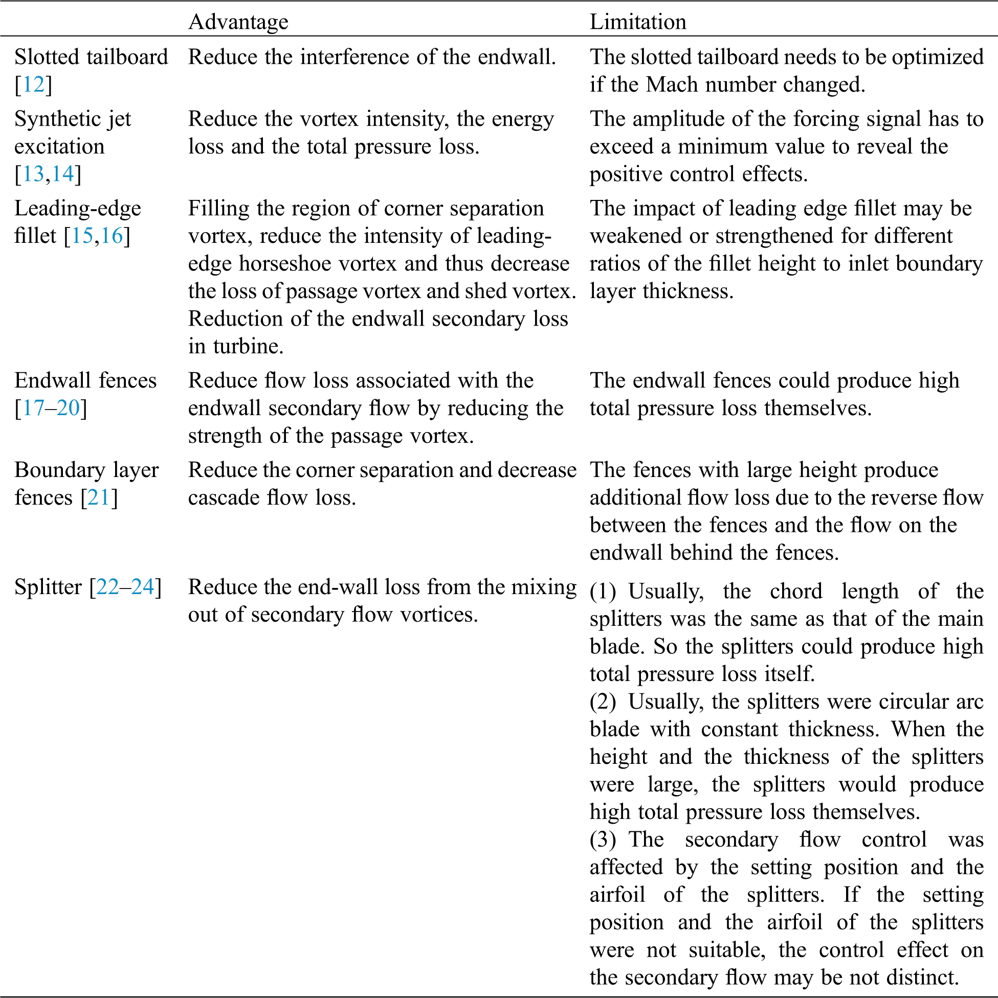
From the studies above, advantages and limitations of different methods to reduce the total pressure loss of secondary flow were shown in Tab. 1.
Table 1: Advantage and limitation of different methods to reduce the total pressure loss of secondary flow
In this study, the splitters at three different relative positions to the main blade were set up to control the secondary flow around the main blade, which was applied to axial fan as the outlet guide vane (OGV). The role of the splitters was to control the secondary flow to improve the efficiency of the cascade. The main purposes of this study were:
(1) Detecting the influence of the splitters at different relative positions to the main blade, which could control the secondary flow around the main blade and have the potential ability to reduce the total pressure loss of the cascade.
(2) Detecting the flow structure near the endwall and on the suction surface of the main blade to discover the influence of the splitters at different relative positions on the secondary flow control of the main blade.
In this study, four blades were chosen to investigate the influence of the splitters at different relative positions to the main blade on the secondary flow control. The arrangement and parameter definition of the investigated blades were shown in Figs. 1 and 2. The airfoil of the main blades were NACA 65-010 profile, which had the camber angle φ of 40° and the stagger angle λ1 of 20°. The chord length L1 was 100 mm and the height b was 200 mm.
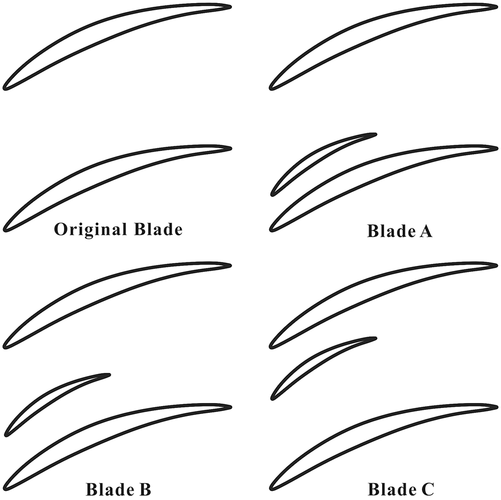
Figure 1: The arrangement of the investigated blades
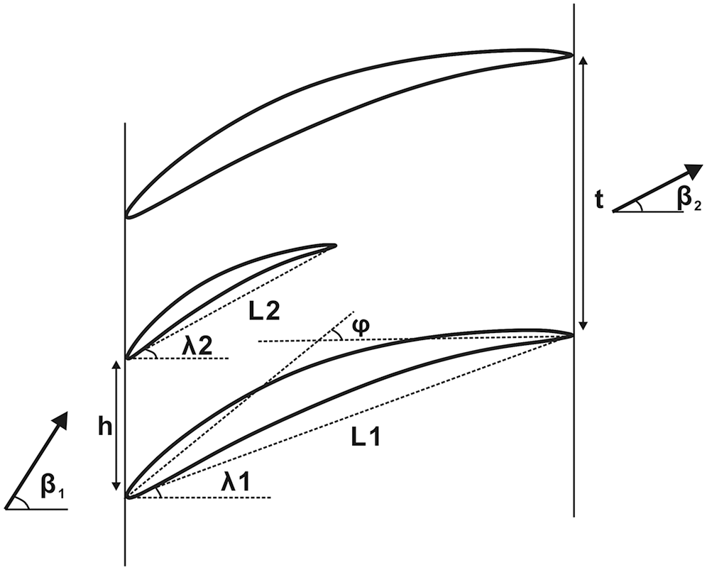
Figure 2: The parameter definition of the investigated blade
The original blade was the main blade without splitters. Blade A, Blade B and Blade C had the splitters at different relative positions to the main blade. The airfoil of the splitters was also NACA 65-010 profile with the camber angle of 40°. The stagger angle λ2 was 28.5° and the chord length L2 was 50 mm.
The setup of the main blade with splitters was shown in Fig. 3 [23]. The spacing ratio t/l of the main blade was 1.0. The distances between the main blade and the splitters h were 20 mm for Blade A, 30 mm for Blade B and 70 mm for Blade C. The height of the splitters b1 was 5 mm. Tab. 2 represented the configuration parameters of the investigated blades.
Table 2: The geometry parameters of the blades
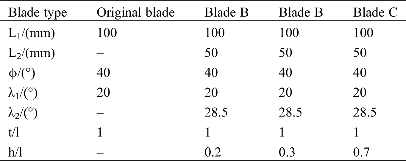
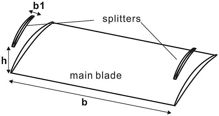
Figure 3: The setup of the main blade with splitters [23]
In this study, the CFD simulations were conducted by ICEM CFD and Fluent from ANSYS 15.0. The three-dimensional block-structured grids were created for the investigated blades. The grids consisted of about 4 million cells. The simulation field of the flow domain was shown in Fig. 4 and the boundary conditions of the flow domain were represented in Tab. 3. The velocity inlet was 50 mm upstream from the leading edge of the main blade, the pressure outlet was 100 mm downstream behind the trailing edge of the main blade. The plane for computing the results was 50 mm downstream behind the trailing edge of the blade.
Table 3: Setup of the boundary conditions of the simulation field
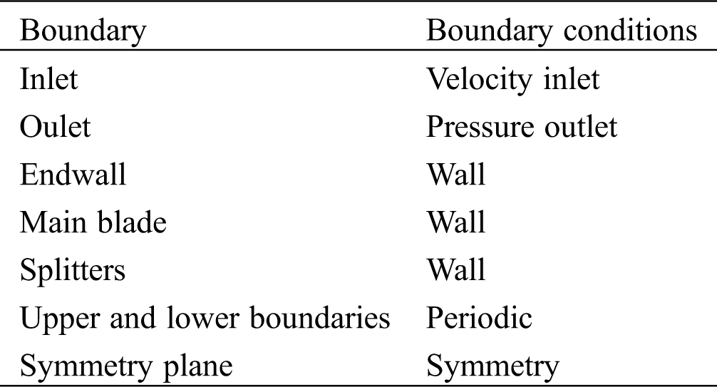
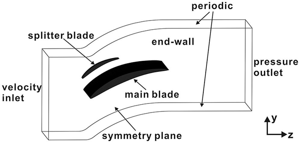
Figure 4: Simulation field of the flow domain [23]
The CFD simulations were conducted by ANSYS Fluent 15.0. Reynolds-Averaged Navier-Stokes equations (RANS) were solved on the grids. The Reynolds-Averaged Navier-Stokes equations for a stationary, incompressible Newtonian fluid are summarized in tensor notation as
where
The assumptions of isothermal (i.e., μ = const.) and steady state conditions were made, so the energy equation was not necessary and no boundary condition for the temperature was set. The first order upwind scheme was used to represent the convection terms of the governing equations. The semi-implicit method for pressure-linked equation (SIMPLE) [25] was used to solve the discretized equations. The simulations were performed at Re = 2 × 10⁵. The velocity of inflow was smaller than Mach number 0.3, so the inflow was considered as incompressible (ρ is consistent). The turbulent intensity was set as 2%, which was tested in the wind tunnel in our lab [23,24]. The turbulent length was set as 0.014 m [24]. The velocity profile on inlet is shown in Fig. 6. The inlet velocity profile in the CFD was fitted by the measurement results of the free field measurement [23].
In the CFD simulations, the transition SST (shear stress transport for short) was chosen as the turbulence model in this study. The grids were refined near the blades and the endwall to detect the flow behavior in the boundary layer of the walls as shown in Fig. 5. According to the recommendation of the ANSYS Fluent 15.0, the maximum y+ should be smaller than 1 for the turbulence model chosen in this study [26], so the maximum height of the first layer of the cells from the walls was set as 0.005 mm.
Figure 5: The profile of the velocity on the inlet, Re = 2 × 10⁵ [23]
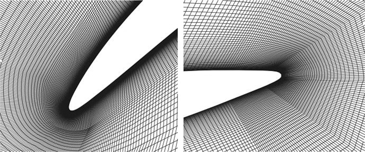
Figure 6: Grids detail near the wall [23]
The test of the grid independence was performed for the original blade [23]. The cell number was doubled near the blade to check whether the grid resolution was sufficient for the simulation work. The grid of original blade has about 4 million cells, Grid 1 has about 4.5 million cells and Grid 2 has about 5 million cells. The result of the grid independence test is shown in Fig. 7. The result indicated that the cell number of the girds had no significant effect on the CFD simulation results.
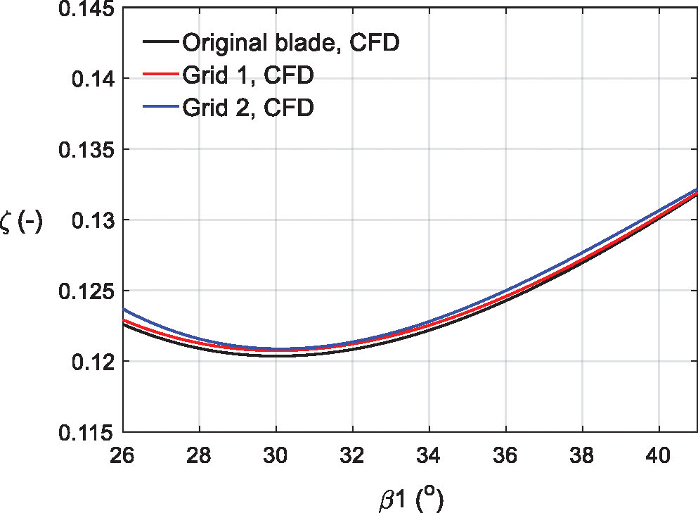
Figure 7: The test of the simulation grid independence [23]
4.1 The Total Pressure Loss and Turning Angle of the Blades
The mass-averaged total pressure loss coefficient was studied to investigate the effect of the splitters at different relative positions to the main blade on the flow loss control.
The mass-averaged total pressure loss coefficient ζ was defined by
where
The experiment was performed for the original blade to validate the CFD simulation results for the original blade. The measurement was conducted in the cascade wind tunnel in Jianghan University as shown in Fig. 8 [23]. It was indicated that the numerical results and the experimental results for the original blade were in a good agreement.
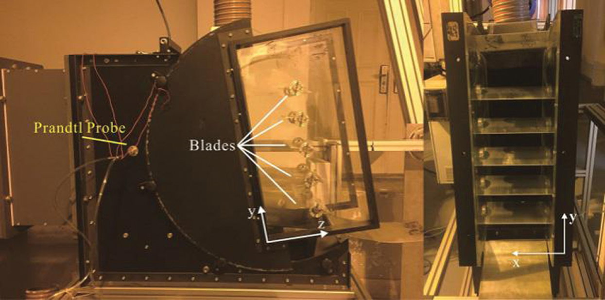
Figure 8: Cascade wind tunnel and experimental section [24]
Fig. 9 compared the mass-averaged total pressure coefficient of the investigated blades. It was indicated that the corresponding inflow angle of the minimal loss coefficient was almost the same at near β1 = 30° for all the investigated blades. Comparing with the original blade, the splitters in the Blade A were found to reduce the total pressure loss coefficient by about 4%. However, the splitters in the Blade B and the Blade C decreased the total pressure loss coefficient comparing with the original blade. It was indicated that only the splitters at the specific relative positions to the main blades could be used to improve the efficiency of the cascade.
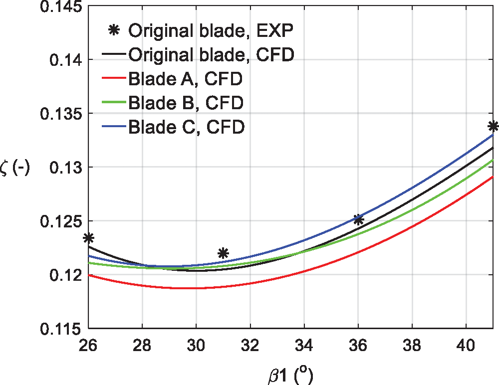
Figure 9: ζ vs. inflow angle of the investigated blades
Fig. 10 compared the turning angles of the studied blades. The turning angle Δβ were defined as [24]
where β1 and β2 were the inflow angle and the flow angle on measuring plane, respectively.
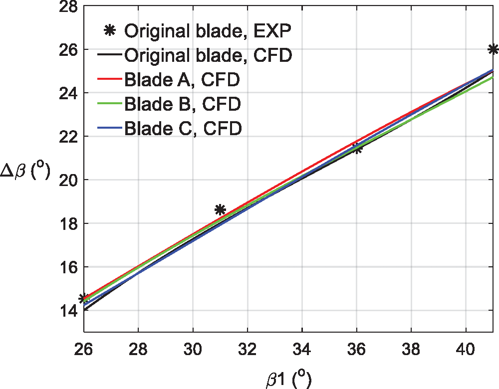
Figure 10: Turning angle in dependence of inflow angle of the investigated blades
The difference between the turning angles of the studied blades was smaller than 1°, so the splitters with different relative positions to the main blade had no significant effect on the turning angle of the blade.
4.2 The Streamline on the Suction Surface of the Main Blade
The streamline on the suction surface of the main blade was studied to investigate the effect of the splitters at different relative positions to the main blade on the flow structure on the suction surface of the main blade in this work.
Fig. 11 shows the streamline on the suction surface of the main blade of the studied blades. The streamline was obtained by the CFD simulations. Under the influence of the friction on the surface of the blade, the splitters and the endwall, there were positive pressure gradients forming in the flow around the trailing edge of the main blade and in the boundary layer of the endwall. Therefore, the flow separation and the vortex occurred in the junction of the endwall and the trailing edge of the main blade.
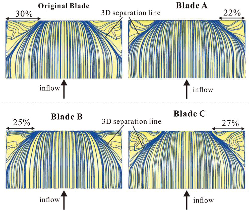
Figure 11: Streamline on the suction surface of the investigated blades, β1 = 33°
In this study, the splitters were set to control the secondary flow in Blade A, Blade B and Blade C. As the result shows, there were smaller separation area in the junction of the endwall and the trailing edge of the main blade in Blade A, Blade B and Blade C than that in the original blade.
With the distance between the splitters and the main blade increasing, the influence of the splitters on the secondary flow control around the main blade became weaker. The separation field near the endwall was about 22% of the height of the Blade A, and the separation field near the endwall for Blade B and Blade C was about 25% and 27% of the height of the blades respectively as shown in Fig. 11.
On the other hand, the flow separation also occur in the flow around the splitters, which could also cause flow loss. Therefore, even though the separation area near the endwall for Blade B (25%) and Blade C (27%) was smaller than that of the original blade (30%), the total pressure loss coefficient of the flow around Blade B and Blade C was higher than the loss coefficient of the original blade. Meanwhile, the separation area near the endwall for Blade A (22%) was also smaller than that of Original Blade (30%), the total pressure loss coefficient of Blade A was smaller than of original blade.
4.3 The Streamline Near the Endwall
Figs. 12 and 13 compared the streamline near the endwall of Blade A and original blade. The streamline was obtained by the CFD simulations. Because the splitters of Blade A controlled the secondary flow around the main blade most effectively and the total pressure loss coefficient of Blade A is also lower than the loss coefficient of original blade.
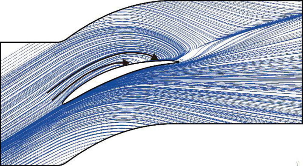
Figure 12: Streamline near the endwall of the Original Blade, β1 = 33°
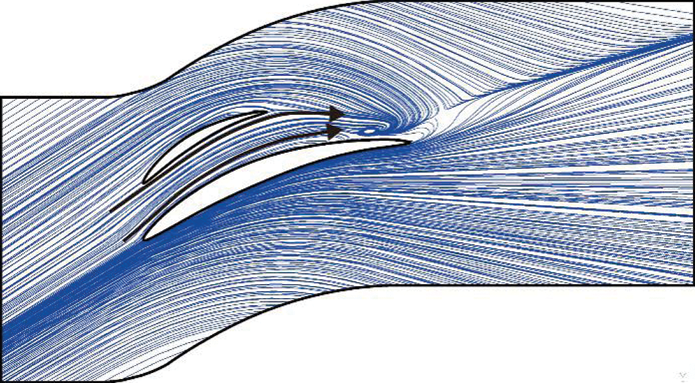
Figure 13: Streamline near the endwall of the Blade A, β1 = 33°
The inflow around the original blade was curved and reattached directly on the suction surface of the main blade as shown in Fig. 12. As a result, a large area of flow separation occurred in the junction of the endwall and the trailing edge of the main blade as shown in Fig. 11.
On the other hand, due to the splitters of Blade A, the reattachment point of the secondary flow to the suction surface of the main blade moved downstream towards the trailing edge of the main blade as shown in Fig. 13. As a result, a smaller flow separation area occurred in the junction of the endwall and the trailing edge of the Blade A as shown in Fig. 11.
4.4 The Distribution of the Total Pressure Loss at the Trailing Edge of the Blades
Figs. 14 and 15 illustrate the distributions of total pressure loss coefficient θ of the flow at the trailing edge of the studied blades.
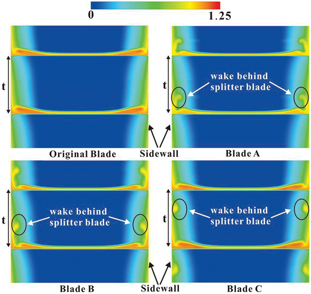
Figure 14: θ at the trailing edge of the investigated blades, β1 = 31°
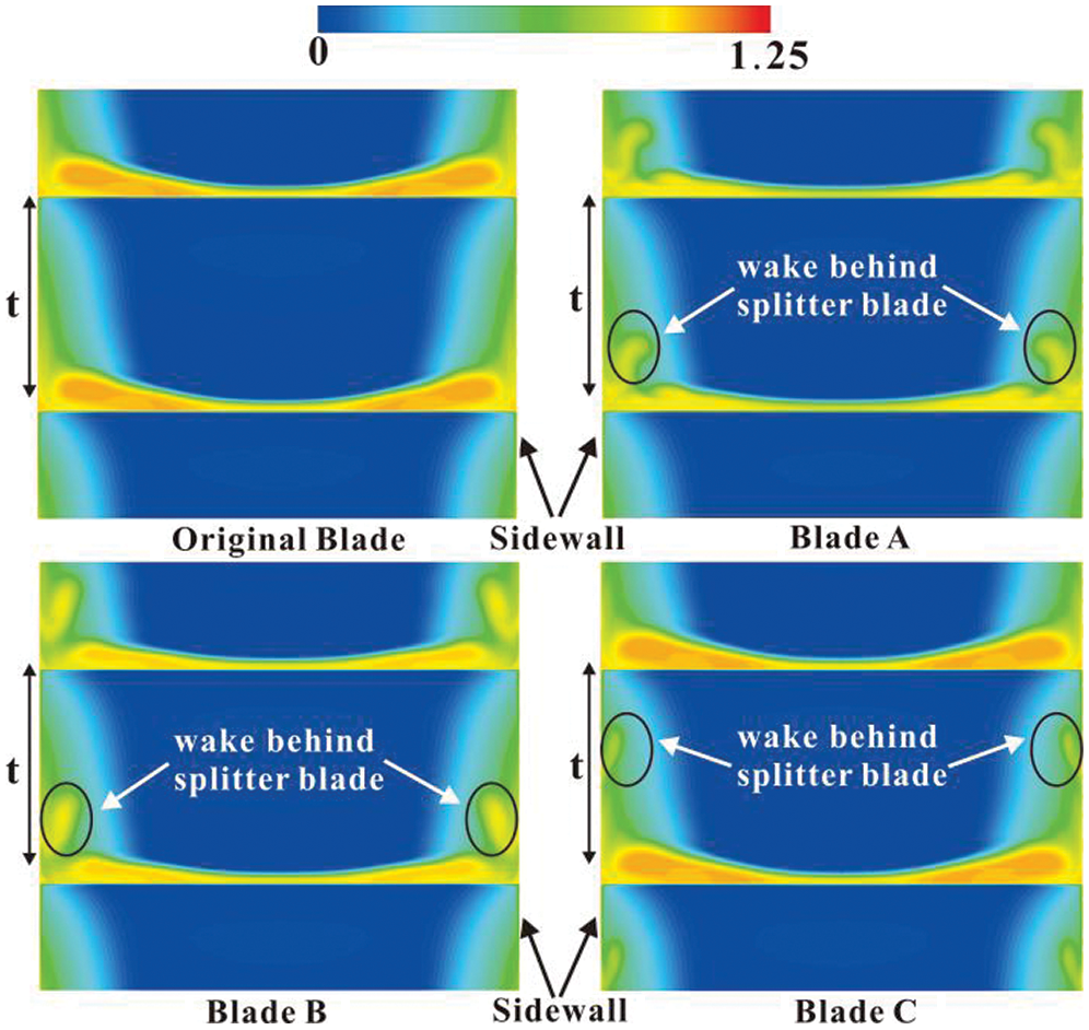
Figure 15: θ at the trailing edge of the investigated blades, β1 = 39°
For the original blade, the total pressure loss of the flow at the trailing edge came from two parts. One part formed in the wake downstream of the blade, which was caused by the flow separation around the main blade. The other part generated in the boundary layer of the flow around the endwall, particularly the flow near the endwall and the main blade.
Besides the high total pressure loss in the wake downstream of the main blade and in the boundary layer of the flow around the endwall, the blades with splitters as Blade A, Blade B and Blade C also had high total pressure loss in the wake downstream of the splitters, which was caused by the flow separation occurred around the splitters. Therefore, the total pressure loss caused by the flow separation around the splitters should also be considered when the splitters were used.
With the distance between the splitters and the main blade decreasing, the influence of the splitters on the secondary flow control around the main blade became stronger. From the investigations above, it was indicated that the splitters of Blade A controlled the secondary flow around the main blade most effectively, so it had the smallest area of the high total pressure loss in the flow in the junction between the endwall and the main blade.
From Figs. 14 and 15, it was indicated that when the inflow angle was larger than the stagger angle of blade, the secondary flow strength grew with the increasing inflow angle, so the area of the high total pressure loss in the flow in the junction between the endwall and the main blade became larger with the increasing inflow angle.
The numerical investigations were conducted to study the influence of the splitters at different relative positions to the main blades on the flow loss and flow structure. The total pressure loss coefficient and the flow structure around the investigated blades were compared to investigate the influence of the relative positions of the splitters to the main blade on the secondary flow control. The splitters could control the secondary flow around the main blade and have the potential ability to reduce the total pressure loss of the flow around the cascade. Comparing with the original blade, blade A was found to reduce the total pressure loss coefficient by about 4%.
In this study, the influence of the splitters on the secondary flow control became stronger with the distance between the splitters and the main blade decreasing. On the other hand, the flow separation also occurred in the flow around the splitters. Therefore, only the splitters at the specific relative positions to the main blade could be used to improve the efficiency of the cascade. The total pressure loss caused by the flow separation around the splitters should also be considered by using splitters.
In addition, the splitters with different relative positions to the main blade provided small influence on the turning angles of the blades.
Funding Statement: This study is supported by the Natural Science Foundation from Hubei Province of China [Grant No. 2019CFC866]; the Guiding Project of Scientific Research Plan of Hubei Education Department of China [Grant No. B2020227]; the Collaborative Innovation Team of Discipline Characteristics of Jianghan University [Grant No. 03100061]; the Research Start-up Funds of Jianghan University [Grant No. 101906320001]; and the Research Start-up Funds of Jianghan University [101906270002].
Conflicts of Interest: The authors declare that they have no conflicts of interest to report regarding the present study.
1. Langston, L. S., Nice, M. L., Hooper, R. M. (1977). Three-dimensional flow within a turbine cascade passage. Journal of Engineering for Gas Turbines & Power, 99(1), 21. [Google Scholar]
2. Moore, J., Adhye, R. Y. (1985). Secondary flows and losses downstream of a turbine cascade. Journal of Engineering for Gas Turbines and Power, 107(4), 961–968. DOI 10.1115/1.3239842. [Google Scholar] [CrossRef]
3. Perdichizzi, A., Dossena, V. (1993). Incidence angle and pitchchord effects on secondary flows downstream of a turbine cascade. Journal of Turbomachinery, 115(3), 383–391. DOI 10.1115/1.2929265. [Google Scholar] [CrossRef]
4. Slitenko, A. F., Jukov, Y. M. (2020). Experimental investigation of three-dimensional secondary flow on the endwall of a blade channel in an axial turbine cascade. Proceedings of the Turbine Technical Conference & Exposition. Munich, Germany. [Google Scholar]
5. Benner, M. W., Sjolander, S. A., Moustapha, S. H. (2004). Measurements of secondary flows downstream of a turbine cascade at off-design incidence. Proceedings of the Turbine Technical Conference & Exposition. Vienna, The Republic of Austria. [Google Scholar]
6. El-Batsh, H., Bassily Hanna, M. (2004). Numerical and experimental prediction of secondary flow through a rectilinear cascade for different aspect ratios. Proceedings of the International Mechanical Engineering Conference (IMEC’04). Kuwait. [Google Scholar]
7. Chen, P. P., Lisener, K., Meyer, R., Qiao, W. Y. (2012). Effect of inflow variations on compressor secondary flow behavior. Fluid Mechanics Conference. Gliwice, Poland. [Google Scholar]
8. El-Batsh, H. M. (2012). Effect of the radial pressure gradient on the secondary flow generated in an annular turbine cascade. International Journal of Rotating Machinery, 2012(1), 1–14. DOI 10.1155/2012/509209. [Google Scholar] [CrossRef]
9. Marks, C. R., Sondergaard, R., Bear, P., Wolff, M. (2016). Reynolds number effects on the secondary flow of profile contoured low pressure turbines. 54th AIAA Aerospace Sciences Meeting. San Diego, California. [Google Scholar]
10. Zambonini, G., Ottavy, X., Kriegseis, J. (2017). Corner separation dynamics in a linear compressor cascade. Journal of Fluids Engineering, 139, 061101/1-061101/13. [Google Scholar]
11. Dai, J. C., Mou, J. G., Liu, T. (2020). Influence of tip clearance on unsteady flow in automobile engine pump. Fluid Dynamics & Materials Processing, 16(2), 161–179. [Google Scholar]
12. Ronaand, A., Gostelow, J. P. (2005). Performance of slotted end wall linear cascade tunnels at off-design conditions. 43rd AIAA Aerospace Sciences Meeting and Exhibit. Reno, USA. [Google Scholar]
13. Liu, Y., Sun, T., Guan, C., Wang, B. (2010). The influence of synthetic jet excitation on secondary flow in compressor cascade. Journal of Thermal Science, 19(6), 500–504. DOI 10.1007/s11630-010-0415-8. [Google Scholar] [CrossRef]
14. Zander, V., Nitsche, W. (2013). Control of secondary flow structures on a highly loaded compressor cascade. Proceedings of the Institution of Mechanical Engineers, Part A: Journal of Power and Energy, 227(6), 674–682. DOI 10.1177/0957650913495538. [Google Scholar] [CrossRef]
15. Wei, Z. J., Qiao, W. Y., Liu, J., Duan, W. H. (2016). Reduction of endwall secondary flow losses with leading-edge fillet in a highly loaded low-pressure turbine. Proceedings of the Institution of Mechanical Engineers, Part A: Journal of Power and Energy, 230(2), 184–195. DOI 10.1177/0957650915619560. [Google Scholar] [CrossRef]
16. Ananthakrishnan, K., Govardhan, M. (2018). Influence of fillet shapes on secondary flow field in a transonic axial flow turbine stage. Aerospace Science and Technology, 82, 425–437. [Google Scholar]
17. Moon, Y. J., Koh, S. R. (2001). Counter-rotating streamwise vortex formation in the turbine cascade with endwall fence. Computers & Fluids, 30(4), 473–490. DOI 10.1016/S0045-7930(00)00026-8. [Google Scholar] [CrossRef]
18. Zhong, J. J., Han, J., Liu, Y. M., Tian, F. (2018). Numerical simulation of endwall fence on the secondary flow in compressor cascade. Turbo Expo: Power for Land, Sea, and Air. vol. 43161, pp. 509–518. Berlin, Germany. [Google Scholar]
19. Chung, J. T., Simon, T. W., Buddhavarapu, J. (1991). Three-dimensional flow near the blade/endwall junction of a gas turbine: application of a boundary layer fence. ASME International Gas Turbine and Aeroengine Congress and Exposition. Orlando, Florida. [Google Scholar]
20. Chung, J. T., Simon, T. W. (1993). Effectiveness of the gas turbine endwall fences in secondary flow control at elevated freestream turbulence levels. ASME International Gas Turbine and Aeroengine Congress and Exposition. Cincinnati, Ohio. [Google Scholar]
21. Hergt, A., Meyer, R., Liesner, K., Nicke, E. (2011). New approach for compressor endwall contouring. Turbo Expo: Power for Land, Sea, and Air. vol. 54679, pp. 177–186. Vancouver, British Columbia. [Google Scholar]
22. Clark, C., Pullan, J., Curtis, J., Groenaga, F. (2017). Secondary flow control in low aspect ratio vanes using splitters. Journal of Turbomachinery, 9, 091003. [Google Scholar]
23. Bian, T., Shen, X., Feng, J. (2020). Numerical study of the influence of splitter geometry on secondary flow control. Proceedings of the Institution of Mechanical Engineers, Part A: Journal of Power and Energy, 32, 095765092096224. DOI 10.1177/0957650920962247. [Google Scholar] [CrossRef]
24. Bian, T., Shen, X., Wang, B., Feng, J., Han, Q. (2019). Numerical and experimental investigation of flow loss and flow structure of circular arc cambered plate blade cascade. Proceedings of the Institution of Mechanical Engineers, Part A: Journal of Power and Energy, 233(8), 961–973. DOI 10.1177/0957650919846006. [Google Scholar] [CrossRef]
25. John, D. (2002). Computational fluid dynamics: The basic with applications. Beijing: Tsinghua University Press. [Google Scholar]
26. Ansys (2013). ANSYS FLUENT User’s Guide Release 15.0. ANSYS Inc., Beijing, China. [Google Scholar]
 | This work is licensed under a Creative Commons Attribution 4.0 International License, which permits unrestricted use, distribution, and reproduction in any medium, provided the original work is properly cited. |