Materials Processing
| Fluid Dynamics & Materials Processing |
DOI: 10.32604/fdmp.2021.014711
ARTICLE
Influence of Nozzle Orifice Shape on the Atomization Process of Si3N4 in a Dry Granulation Process
1School of Mechanical and Electronic Engineering, Jingdezhen Ceramic Institute, Jingdezhen, 333403, China
2National Engineering Research Center for Domestic & Building Ceramics, Jingdezhen, 333001, China
*Corresponding Authors: Nanxing Wu. Email: ldhjdz1987@163.com; Dahai Liao. Email: 15172480512@163.com
Received: 23 October 2020; Accepted: 05 February 2021
Abstract: In order to reveal the intrinsic fluid-dynamic mechanisms of a pressure-swirl nozzle used for Si3N4 dry granulation, and effectively predict its external spray characteristics, the dynamics of air-atomized liquid two-phase flow is analyzed using a VOF (Volume of Fraction) method together with the modified realizable k-ε turbulence model. The influence of nozzle orifice shape on velocity distribution, pressure distribution is studied. The results show that the pressure difference in a convergent conical nozzle is the largest with a hollow air core being formed in the nozzle. The corresponding velocity of atomized liquid at nozzle orifice is the largest. Using a self-designed atomization experiment platform, the velocity and pressure of atomized liquid and the spray cone angle are measured for three nozzles with different orifice shapes. The micro-morphology of Si3N4 particles is also determined. These data confirm the correctness of numerical simulation. Considering atomization performance of the nozzle, the contraction conical nozzle is more suitable for the atomization of Si3N4 in practical production based on the dry granulation approach.
Keywords: Si3N4 dry granulation; pressure-swirl nozzle; VOF method; nozzle orifice shape
Si3N4 dry granulation has many advantages over traditional Si3N4 wet granulation, such as a simple process, high cost-effectiveness and water and energy-saving [1–4]. Atomization is an important process in Si3N4 dry granulation. Its function is to combine atomized droplets from a nozzle with homogeneous Si3N4 powder to provide boundary conditions for subsequent the granulation processes. The size of atomized droplets can affect the percentage of powder in Si3N4 particles prepared by dry granulation. The pressure-swirl nozzle is one of the essential components of the atomization process for Si3N4 dry granulation. The velocity distribution, pressure distribution, spray cone angle, the thickness of liquid film and other characteristic parameters near nozzle play a decisive role in the primary breakup of the liquid film, the secondary breakup of the liquid zone and final droplet size [5–8]. However, relevant studies have shown that the nozzle orifice shape can affect the gas-liquid flow, the formation and evolution of the liquid film in the nozzle, and ultimately the size of atomized droplets [9,10]. Therefore, to predict and optimize the spray characteristics of the pressure-swirl nozzle more accurately, it is necessary to study the influence of nozzle orifice shape on the spray characteristics of Si3N4 dry granulation.
It is difficult to measure the related parameters of internal flow field of the nozzle by experiment, in spite of its advantages of simple structure, low kinetic energy consumption and excellent atomization performance. With the rapid development of numerical calculation and computer technology, numerical simulation has been used to study the internal flow characteristics of pressure-swirl nozzle [11–15]. Ronny et al. [16,17] used CFD (Computational Fluid Dynamics) method to study the influence of nozzle orifice shape on the flow characteristics of a premixed injector. The results showed that the nozzle orifice shape of the premixed injector had an influence on the flow characteristics of the injector and indirectly affected the emission of the burner system. Mund et al. [18] studied the effect of nozzle shape on the flow and solidification characteristics during top pouring by CFD method. The results showed that, compared with the square, triangular and elliptical nozzles, circular nozzles had uniform solidification and no defect zone, and were most suitable for high-speed twin-roll strip caster. Macías-Hernández et al. [19] used the CFD method to study the interface instability in the development of core-annulus flow in horizontal nozzles. By increasing the water input ratio, under the action of input pressure, turbulent flow force and buoyancy, when the core was in the upward position and oscillation position, the interface instability occurred. Belhadef et al. [20,21] used CFD method to study the atomization process of pressure-swirl nozzle, solving the average density equilibrium equation of liquid-gas interface, and finally obtained the average diameter of droplets. Jia et al. [22] used mixed multiphase model and full cavitation model to simulate the conical injector. The results showed that the evolution of cavitation had a significant effect on the thickness and velocity of liquid film at the nozzle orifice, changing the spray angle and the average droplet diameter. In conclusion, although the above research object is not the flow field of pressure-swirl nozzle for Si3N4 dry granulation, it can also provide some theoretical reference for the flow field research of pressure-swirl nozzle for Si3N4 dry granulation.
Based on previous studies on the flow field of related nozzles, a three-dimensional geometric model of pressure-swirl nozzles for Si3N4 dry granulation with different orifice shapes is established in this paper. The simulation area of the nozzle is simplified, and the hybrid meshes are used to divide the three-dimensional physical model of the nozzle. Based on the VOF (Volume of Fluid) method, the dynamics of air-atomized liquid two-phase flow in the nozzle is analyzed, and the modified realizable k-ε turbulence model is used to calculate the three-dimensional flow field in the nozzle, the influence of nozzle orifice shape on velocity distribution, pressure distribution, spray cone angle and the thickness of the liquid film is analyzed. Based on the self-designed atomization experimental platform, the correctness of numerical analysis is verified. The method and conclusion can reveal the development law of the internal and external velocity, pressure, spray cone angle and liquid film thickness of the nozzle, and understand the flow and evolution characteristics of the pressure swirling Si3N4 dry granulating nozzle, so as to provide the effective basis for predicting and optimizing the spray atomization of the nozzle.
2 Flow Mechanism in the Nozzle
The pressure-swirl nozzle has the advantages of simple structure, low kinetic energy consumption and excellent atomization performance [23–25]. It is widely applied in the processes of industrial boilers, spray drying, gas turbines, agricultural irrigation and atomization granulation industries, etc. The atomization mechanism of the pressure-swirl nozzle is shown in Fig. 1. Under the action of pressure, the atomized liquid enters into the nozzle through four tangential ports, forming a high-speed rotating motion in the swirl chamber. Then the rotating atomized liquid is thrown to the wall of the swirl chamber by centrifugal force and the air core along the central line appears in the nozzle. At the same time, the atomized liquid expands to nozzle orifice by a high-speed rotating motion from top to bottom. As a result of the action of centrifugal force, a hollow conical liquid film is formed at the orifice. After leaving the orifice, the hollow conical liquid film becomes wider gradually, and the internal and external surfaces of the hollow conical liquid film can form waves. The wave on the liquid film is amplified by the aerodynamic force generated by the difference between the liquid film velocity and the surrounding gas velocity. These waves increase in time and space until they reach a critical amplitude, which leads to the breakdown of the liquid film and eventually splits into tiny atomized droplets [26,27].
Figure 1: Atomization mechanism of pressure-swirl nozzle
3 Equations and Mathematical Expressions
(1) VOF method
The VOF method proposed by Hirt et al. [28], is a linear interpolation method for describing the motion of the continuous phase and the coupling between the continuous phase and dispersed phase [29,30]. It can reconstruct the interface without changing the mesh and trace the gas-liquid two-phase flow interface accurately in the nozzle, and then the coupling problem between any two incompressible fluids is solved. The two incompressible fluids are immiscible and the seepage and slip between the two phases are negligible. The advantage of the VOF method is that it has no topological constraints, and it defines a scalar volume fraction function γ to represent the volume fraction of the second phase in a computational mesh. In this paper, the working substances are atomized liquid and air, which are suitable for the VOF method. The volume fraction of a scalar field function is defined to represent the volume fraction of the second fluid in the nozzle mesh calculation area. If γ = 0, the mesh calculation area of the nozzle is all the first fluid. If 0 < γ < 1, part of the mesh calculation area of the nozzle is the first fluid and the other part is the second fluid. If γ = 1, the mesh calculation area of the nozzle is all second fluid. In this paper, air is the first fluid and atomized liquid is the second fluid. It defines as:
when the gas-liquid interface is affected by the flow, the evolution of scalar γ is governed by the simple advection equation:
The scalar volume fraction function γ can provide the precondition for solving the average variables of the internal flow field of nozzle, such as the local density ρ and the local dynamic viscosity μ of fluid are typically interpolated across the interface as follows:
where subscript g represents air and subscript l represents atomized liquid.
(2) Control equations
The control equations in this paper are all based on the classical Navier-Stokes equations. According to the analysis of the actual flow field of the nozzle, there is no chemical reaction and physical phase change between gases and liquid in the nozzle, in other words, there is no energy change involved. Further, the heat exchange between phases and phases is not considered. The flow is treated as incompressible. The control equations are as following:
Mass conservation equation:
Momentum equation:
where u is fluid velocity vector, t is the time of atomized liquid filling nozzle, ρ is fluid density, μ is the dynamic viscosity of atomized liquid, P is time-averaged pressure, m is gravitational body force, G is the gravity, m is the mass of atomized liquid, g is the coefficient of gravity, F is surface tension force, σ is the surface tension acting on the unit interface, l is the length of atomized liquid.
The purpose of numerical simulation is to compare and analyze the influence of nozzle orifice shape on the internal flow field of the nozzle by changing the structural parameters of the pressure-swirl nozzle for Si3N4 dry granulation. The object of this study is a press re-swirl nozzle for Si3N4 dry granulation with four tangential inlets, and its structure is shown in Fig. 2. Fig. 2a is a cylindrical nozzle, which is composed of a swirl chamber, a contraction section and a straight section. Further, Fig. 2b is a contraction conical nozzle: its main structure includes a swirl chamber, a contraction section 1, a straight section and a contraction section 2. However, Fig. 2c is an expansion conical nozzle, which is composed of a swirl chamber, a contraction section, a straight section and an expansion section. This paper mainly focuses on the establishment of two-phase flow and the flow field in the process of atomizing liquid filling pressure-swirl nozzle, so it is necessary to simplify the simulation area of the pressure-swirl nozzle. The origin of the numerical calculation domain is located at the center of the top of the nozzle swirl chamber, and the Z-axis is chosen as the center axis of the nozzle.
Figure 2: Simulated area of pressure-swirl nozzle with different orifice shapes (a) Cylindrical nozzle (b) Contraction conical nozzle (c) Expansion conical nozzle
The geometric parameters of pressure-swirl nozzles with different orifice shapes are shown in Tab. 1, where L is the total length of the nozzle, LS is the length of swirl chamber, L0 is the length of the nozzle orifice, DS is the diameter of swirl chamber, d0 is the diameter of nozzle orifice, dt is the diameter of tangential inlet, φ is contraction angle.
Table 1: Structural parameters of different nozzles
In the numerical simulation, the atomized liquid with a density of 2000 kg/m3 and viscosity of 0.7 kg/(m∙s) is selected as the working medium. In a two-phase model, the friction heat between atomized liquid and the wall of the nozzle is neglected, and the effect of gravity is considered. Because the boundary conditions of three nozzles with different orifice shapes are the same, only one kind of cylindrical nozzle is selected as the research object, and its physical model is shown in Fig. 3. The boundary condition at the nozzle inlet is set to velocity inlet, the velocity is 1.17 m/s, and the volume fraction of the atomized liquid is set to 1, which means that only the atomized liquid enters the nozzle. When the flow field is initialized, the volume fraction of atomized liquid in the nozzle is 0. Further, The boundary condition of the nozzle orifice is set to pressure outlet, the gauge pressure is set to standard atmosp heric pressure, and the integral number of atomized liquid is set to 0, which means that the atomized liquid does not return to the computational mesh area after flowing out of the nozzle orifice to participate in a numerical calculation, so as to ensure the accuracy of numerical calculation. Nevertheless, the remaining exterior surface of the nozzle is calculated by standard wall function.
Figure 3: Physical model of pressure-swirl nozzle
In this paper, ICEM (The Integrated Computer Engineering and Manufacturing Code) is used to mesh three pressure-swirl nozzles with different orifice shapes. The mesh model of pressure-swirl nozzles with different orifice shapes is shown in Fig. 4. Because of the complex structure of the tangential inlet section and swirl chamber, it is difficult to divide them with structural mesh. Therefore, the tetrahedral mesh is used to divide the tangential inlet section and the swirl chamber, and O-block is used to divide the rest of them into the hexahedral mesh. Relevant studies have shown that the accuracy of mesh has a significant impact on the spray cone angle and the breakup length of the liquid film and poor mesh quality will result in inaccurate capture of air-core at nozzle axis [31]. The mesh quality is evaluated by skewness. Therefore, in order to improve the calculation accuracy and control the computing resources efficiently, the prism mesh is used to densify local mesh at the tangential inlet and the intersection area between the tangential inlets and swirl chamber. Finally, mesh quality is checked accordingly, the cylindrical nozzle has 172298 mesh elements and 91812 nodes, and the skewness is more than 0.5. The contraction conical nozzle has 134171 mesh elements and 59874 nodes, and the skewness is more than 0.55. The expansion conical nozzle has 154405 mesh elements and 77230 nodes, and the skewness is more than 0.4. The maximum mesh of three nozzles is set to 0.5 mm, which ensures the accuracy of calculation and facilitates the accurate capture of the two-phase interface.
Figure 4: 3D mesh model of pressure-swirl nozzle (a) Cylindrical nozzle (b) Contraction conical nozzle (c) Expansion conical nozzle
3.5 Discretization and Solution of Equations
In order to accurately solve the flow field of pressure-swirl nozzles with different orifice shapes, an implicit unsteady solver is selected as the calculation basis. The pressure-velocity coupling method is SIMPLEC iteration, the pressure interpolation method uses PRESTO variance. It is very significant to obtain higher accuracy, so the courant number is controlled below 0.25, the volume fraction equation and momentum equation are discretized by second-order upwind formula, and the convergence residuals of variables are less than 10−4. The sub-relaxation factor is used to enhance the stability of calculation. The time step length is 10−5 s and the maximum iteration time is 200 times at most. The condition of convergence is that the outlet flow rate of atomized liquid is equal to the inlet flow rate, the outlet flow rate is no longer changed, and the gas-liquid mixing interface tends to be stable.
4 Computational Results and Discussion
4.1 Spray Cone Angle and the Thickness of Liquid Film
The volume fraction distribution of atomized liquid in pressure-swirl nozzles with different orifice shapes is shown in Fig. 5. The air core mainly appears in the following parts of the axis of the swirl chamber of cylindrical nozzle, while the air core always mainly appears in the axes of contraction conical nozzle and expansion conical nozzle. Similarly, the diameter of the air core of nozzles with different orifice shapes increases gradually in the way of conical expansion, but the magnitude of increase is different. The diameter of the air core at the orifice of cylindrical nozzle are the largest, while the air core at the orifice of contraction conical nozzle is slightly larger than the expansion conical nozzle. Actually, the diameter of an air core at orifice will indirectly affect the spray cone angle, the larger the diameter of an air core, the larger the spray cone angle of atomized liquid sprayed from nozzle. In a certain range, the diameter of air core increases, which is beneficial to atomization, but when the air core exceeds a certain range, the atomization effect decreases. In summary, the atomization effect of contraction conical nozzle is the best.
Figure 5: Volume fraction distribution of atomized liquid (a) Cylindrical nozzle (b) Contraction conical nozzle (c) Expansion conical nozzle
4.2 Distribution of Pressure Field
(1) Axial pressure distribution in nozzle
The axial pressure distribution in pressure-swirl nozzles with different orifice shapes is shown in Fig. 6. In the flow field of the nozzle, the pressure decreases in turn along the axis. The atomized liquid enters the swirl chamber with four tangential inlets and makes a high-speed downward rotation. The power comes from axial kinetic energy converted from partial pressure potential energy. The area relationship of the pressure range from 2.8 kPa to 3.0 kPa in three nozzles with different orifice shapes is as follows: S2 < S3 < S1, it shows that when the atomized liquid is filled with three nozzles with different orifice shapes, cylindrical nozzle and expansion conical nozzle need more pressure to realize atomization, and the atomization effect is not better than that of contraction conical nozzle. Besides, excessive pressure could lead to excessive heat loss caused by the high-speed rotating movement of atomized liquid along the wall below the swirl chamber. Furthermore, the pressure at the orifice of three nozzles with different orifice shapes is lower than that in the external environment, the pressure difference between the inside and the outside of the nozzle results in the air from the outside being sucked back into the inside of the nozzle, which makes that the air core is formed at the central axis of the nozzle. Combining with Fig. 5, it can be seen that under the same working conditions, the energy dissipation of the contraction conical nozzle is the smallest and the atomization effect is better than that of the cylindrical nozzle and expansion conical nozzle.
Figure 6: Axial pressure distribution in nozzle (a) Cylindrical nozzle (b) Contraction conical nozzle (c) Expansion conical nozzle
(2) Tangential pressure distribution in nozzle
To further understand the influence of orifice shape on the pressure distribution in the nozzle, taking Z = 30 sections as an example, the tangential pressure distribution of three nozzles with different orifice shapes is shown in Fig. 7. The pressure of the tangential inlet straight section of three nozzles with different orifice sh1apes reaches maximum, which indicates that changing nozzle orifice shapes will not affect the pressure distribution of the tangential inlet straight section of the nozzle. However, the changes of nozzle orifice shape will affect the pressure distribution of the swirl chamber. When the atomized liquid enters the swirl chamber, because part of the pressure potential energy is converted into axial kinetic energy, the atomized liquid rotates downward at high speed in the swirl chamber. At this time, the pressure in the swirl chamber of three nozzles with different orifice shapes decreases from outward to inward, but the attenuation degree of pressure is different. The pressure gradient is 2.4–2.8 MPa in the center of the swirl chamber of cylindrical nozzles, which account for about 20% of the total area. Furthermore, the pressure area in the center of the swirl chamber of the expansion conical nozzle is 2.2–2.8 MPa, which accounts for about 30% of the total area. However, there is a pressure gradient of 1.8–2.8 MPa in the center of the swirl chamber of the contraction conical nozzle, which accounts for about 50% of total areas. It shows that in the same filling time, cylindrical nozzle and expansion conical nozzle need more pressure to make atomized liquid rotate at high speed, while contraction conical nozzle does not need too much pressure to make atomized liquid rotate at high speed, and the atomization effect is better than that of the cylindrical nozzle and expansion conical nozzle.
Figure 7: Tangential pressure distribution in nozzle (a) Cylindrical nozzle (b) Contraction conical nozzle (c) Expansion conical nozzle
4.3 Velocity Field Distribution of Atomized Liquid
(1) Axial velocity distribution of atomized liquid
The axial velocity distribution in pressure-swirl nozzles with different orifice shapes is shown in Fig. 8, combining with the axial velocity vector distribution of atomized liquid as shown in Fig. 9, the atomized liquid flows along the axes of nozzles with three different orifice shapes to one-third of axes, and the velocity of atomized liquid increases gradually. The velocity of atomized liquid of cylindrical nozzle and expansion conical nozzle reaches the maximum at one-third of the axis, then decreases gradually along the axis direction. However, the axial velocity of the atomized liquid at the axis one-third of contraction conical nozzle also increases but does not reach maximum, then decreases gradually along an axis to orifice straight section, and finally increases in turn along the axis to the orifice, and the velocity of atomized liquid reaches a maximum at the orifice. It shows that because the resistance of atomized liquid along the axis one-third of the nozzle with three different orifice shapes is small, so the velocity increases sharply here. But at the orifice, only the velocity of atomized liquid in the contraction conical nozzle reaches maximum. The greater the velocity of the atomized liquid, the greater the velocity difference between atomized liquid and external air, and the greater the aerodynamic force will be generated, which will eventually lead to the breakup of the atomized liquid film and the formation of smaller atomized droplets. The axial velocity of the atomized liquid at the orifice of the contraction conical nozzle is the largest and the atomization effect is the best.
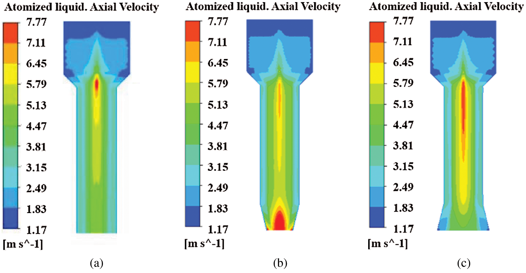
Figure 8: Axial velocity distribution of atomized liquid (a) Cylindrical nozzle (b) Contraction conical nozzle (c) Expansion conical nozzle
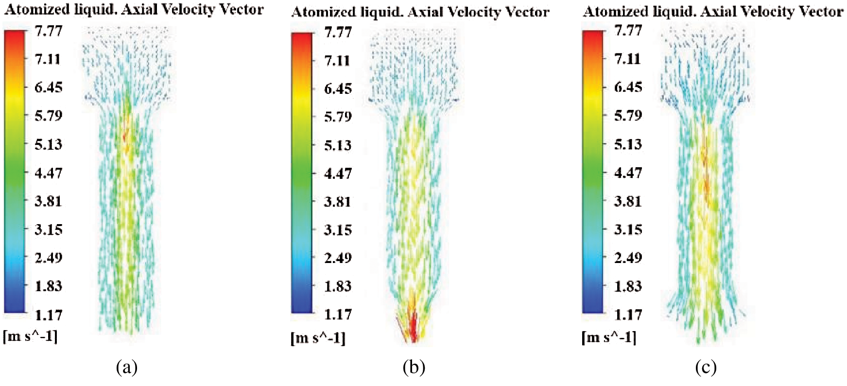
Figure 9: Axial velocity vector distribution of atomized liquid (a) Cylindrical nozzle (b) Contraction conical nozzle (c) Expansion conical nozzle
(2) Radial velocity distribution of atomized liquid
To describe more vividly the radial velocity distribution of atomized liquid in nozzles with different orifice shapes, taking the Z = 2 section as an example, the radial velocity distribution in pressure-swirl nozzles with different orifice shapes is shown in Fig. 10, it is necessary to synthetically analyze the radial velocity vector distribution of atomized liquid as shown in Fig. 11. It can be seen from the figure that the atomized liquid moves strongly in three nozzles with different orifice shapes. The radial velocity of the atomized liquid is the smallest on both sides of the expansion cone nozzle hole, and the velocity at the center of the expansion cone nozzle hole is roughly the same as that of the cylindrical nozzle. However, compared with cylindrical nozzle and expansion conical nozzle, the radial velocity of both sides of atomized liquid at the orifice of contraction conical nozzle is larger, and the velocity at the center of the orifice reaches maximum. It shows that the strong swirling effect of atomized liquid in cylindrical nozzle and expansion conical nozzle is not as strong as that of contraction conical nozzle, the velocity of atomized liquid from contraction conical nozzle is the highest, and the atomization effect is better by strengthening the falling off and breaking of the liquid film.
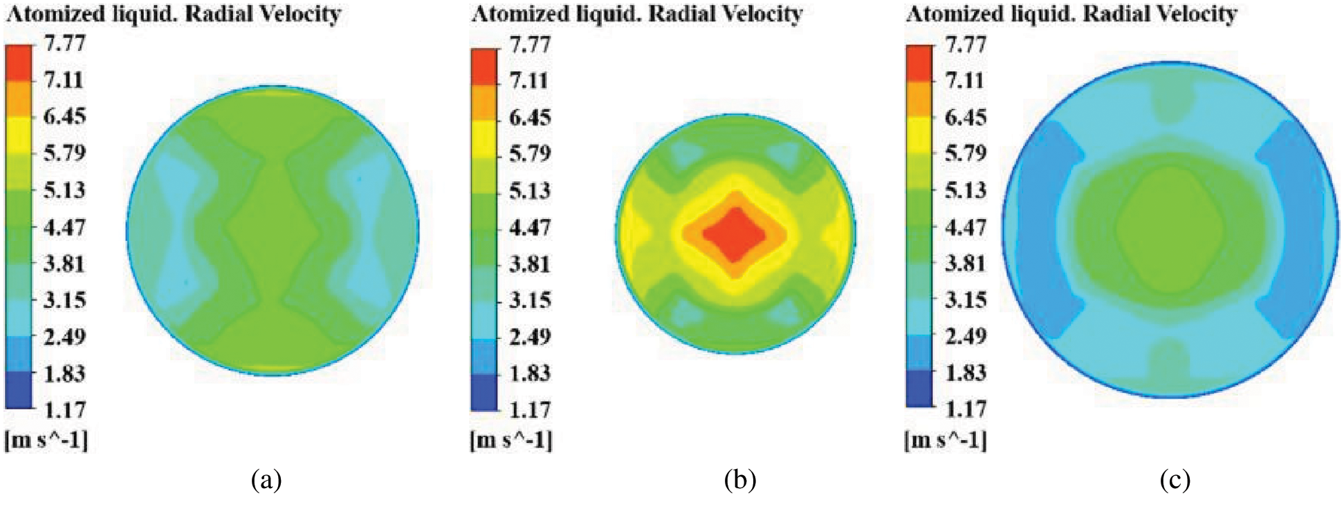
Figure 10: Radial velocity distribution of atomized liquid (a) Cylindrical nozzle (b) Contraction conical nozzle (c) Expansion conical nozzle
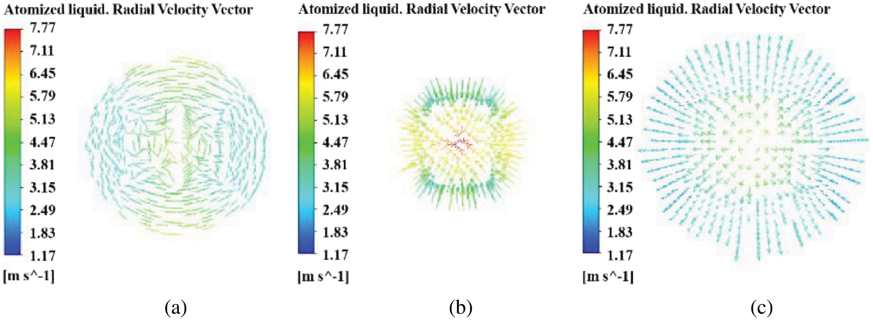
Figure 11: Radial velocity vector distribution of atomized liquid (a) Cylindrical nozzle (b) Contraction conical nozzle (c) Expansion conical nozzle
(3) Tangential velocity distribution of atomized liquid
To further understand the influence of the velocity field of atomized liquid on the atomization characteristics of nozzles with different orifice shapes, it is necessary to analyze the tangential velocity distribution of atomized liquid in the nozzle. Taking the Z = 30 section as an example, the tangential velocity distribution in pressure-swirl nozzles with different orifice shapes is shown in Fig. 12, and the tangential velocity vector distribution of atomized liquid is shown in Fig. 13. It can be seen that the tangential velocity distribution of atomized liquid in nozzles with three different orifice shapes is approximately the same. The atomized liquid rotates at high speed along the tangential inlet of nozzles with three different orifice shapes, the tangential velocity of atomized liquid reaches a maximum when it enters the tangential inlet, then decreases gradually. However, when atomized liquid flows into a swirl chamber, at this time, the tangential velocity is the smallest. It shows that the change of orifice shape does not affect the tangential velocity distribution of atomized liquid in the nozzle, but has some influence on the axial and radial velocity distribution of atomized liquid in the nozzle.
Figure 12: Tangential velocity distribution of atomized liquid (a) Cylindrical nozzle (b) Contraction conical nozzle (c) Expansion conical nozzle
Figure 13: Tangential velocity vector distribution of atomized liquid (a) Cylindrical nozzle (b) Contraction conical nozzle (c) Expansion conical nozzle
5.1 Construction of Experimental Platform
In order to verify the correctness of numerical analysis, the atomization experimental platform is presented in Fig. 14. The raw material used in the experiment is Si3N4 powder from Alfa Aesar (China) Chemical Co., Ltd. (mean particle size 0.5 μm, α phase > 98.5 wt%), and the atomized liquid is sodium alginate solution with the density of 2000 kg/m3 and the viscosity of 0.7 kg/(m∙s), the density, viscosity and surface tension of the atomized liquid is measured by a densitometer, viscometer and surface tensiometer respectively, so that the experimental parameters and the parameters of numerical simulation are consistent. The workflow of the experimental platform is as follows: First, the properly proportioned atomized liquid is poured into the piston, and then the electromotor is started. Further, the electromotor transmits its power to gear acceleration mechanism, at this time, because the rotation speed of the shaft is too high to be controlled, the rotation speed of the shaft is adjusted to the optimum by the reducer, and the power is transferred to crank slider mechanism by the reducer, the piston extrusion mechanism is driven to work by the forward motion of a slider. The atomized liquid enters into a pressure-swirl nozzle along the flow channel and eventually sprays out from the orifice to the external environment for a complete atomization process.
Figure 14: A sketch of experimental system. 1-Frame, 2-Electromotor, 3-Gear acceleration mechanism, 4-Reducer, 5-Crank slider mechanism, 6 Piston extrusion mechanism, 7-Atomized liquid, 8-Flow control valve, 9-Flowmeter, 10-Flow channel, 11-Pressure sensors, 12-pressure-swirl nozzle, 13-Atomized droplet, 14-Si3N4 particles, 15-High-performance digital camera, 16-Scanning electron microscopy, 17-High-performance computer
I, II, III and IV are experimental processes respectively. The Process I am to mix atomized droplets sprayed from nozzles with different orifice shapes with uniform Si3N4 powder, completing the second stage of the atomization process of dry granulation, and finally obtain Si3N4 particles corresponding to nozzles with different orifice shapes through the process of dry granulation. In Process II, a high-performance digital camera is used to photograph atomized liquid from the nozzle orifice. Process III is to observe the micromorphology of Si3N4 particles produced by nozzles with different orifice shapes by scanning electron microscopy. In Process IV, the high-performance computer is used to post-process the photographs of spray cone angle and micromorphology of Si3N4 particles taken from nozzles with different orifice shapes.
5.2 Experimental Results and Discussion
(1) Pressure analysis
In order to further verify the correctness of numerical simulation, the pressure of gas-liquid two-phase flow in nozzles with different orifice shapes is measured by pressure sensors (Shenzhen Jingchenpu Technology Co., Ltd.; Accuracy grade: 0.1% FS), the numerical simulation and experimental results are shown in Fig. 15. The pressure along the nozzle axis is the pressure on the nozzle wall. It can be seen that when the atomized liquid rotates axially at high speed in nozzles with different orifice shapes, the pressure curve of the contraction conical nozzle fluctuates greatly when the axial distance increases from 0.003 m to 0.006 m, the pressure increases from 25365 Pa to 29821 Pa. However, on the whole, the pressure curves of the cylindrical nozzle and expansion conical nozzle fluctuate slightly, and the pressure increases slightly. When the axial distance exceeds 0.006 m, the pressure decreases with the increase of axial distance, and the pressure curves of three nozzles with different orifice shapes fluctuate slightly. Compared with cylindrical nozzle and expansion conical nozzle, the pressure in the swirl chamber of the contraction conical nozzle is the smallest, which results in a greater pressure difference with external air. The external air is absorbed into the nozzle to form a hollow air core, so the atomization effect of the contraction conical nozzle is better. The fitting degree between the curve of numerical simulation and the experimental curve is good, which verifies the correctness of numerical simulation.
Figure 15: Analysis of internal pressure of nozzles with different orifice shapes (a) Cylindrical nozzle (b) Contraction conical nozzle (c) Expansion conical nozzle
(2) Velocity analysis
The velocity distribution in nozzles with different orifice shapes also has an important influence on the atomization effect. To further verify the correctness of numerical simulation, from the formulas M = ρvA, A = πr2, M is the mass flow rate of fluid, ρ is the density of the fluid, v is the velocity of the atomized liquid, A is the cross-sectional area of nozzle, r is the section radius of the nozzle, v = M/ρA is obtained, the mass flow rate of atomized liquid in nozzles with different orifice shapes are recorded by a flowmeter, and the velocity of the atomized liquid is obtained indirectly, the velocity distribution in nozzles with different orifice shapes is shown in Fig. 16. The velocity along the nozzle axis is the velocity on the nozzle wall. It can be seen that the velocity of atomized liquid in the cylindrical nozzle and expansion conical nozzle increases gradually with the increase of axial distance before the axial distance is 0.012 m. At the position of 0.12 m, the velocity of atomized liquid in the cylindrical nozzle and expansion conical nozzle is 7.2 m/s and 7.3 m/s, respectively. Then, with the further increase of axial distance, the velocity of the atomized liquid decreases gradually. The velocity at the orifice of the cylindrical nozzle and expansion conical nozzle is 4.02 m/s and 4.24 m/s, respectively. However, before the axial distance of the contraction conical nozzle is 0.12 m. The changing trend of velocity is the same as that of the cylindrical nozzle and expansion conical nozzle. While at the axial distance of 0.12 m, the velocity is 6.41 m/s, which is smaller than that of the cylindrical nozzle and expansion conical nozzle. But with the further increase of axial distance, the velocity of the atomized liquid decreases first and then increases. Finally, at the orifice of the contraction conical nozzle, the velocity of the atomized liquid is 7.35 m/s. At the orifice of nozzles with different orifice shapes, the velocity of atomized liquid of contraction conical nozzle is the largest, which makes the velocity difference between atomized liquid and outside air bigger, produces greater aerodynamic force, speeds up the breakup of the liquid film, and forms smaller atomized droplets, which is more conducive to atomization. The experimental results are in good agreement with the results of numerical simulation, which verifies the correctness of numerical simulation.
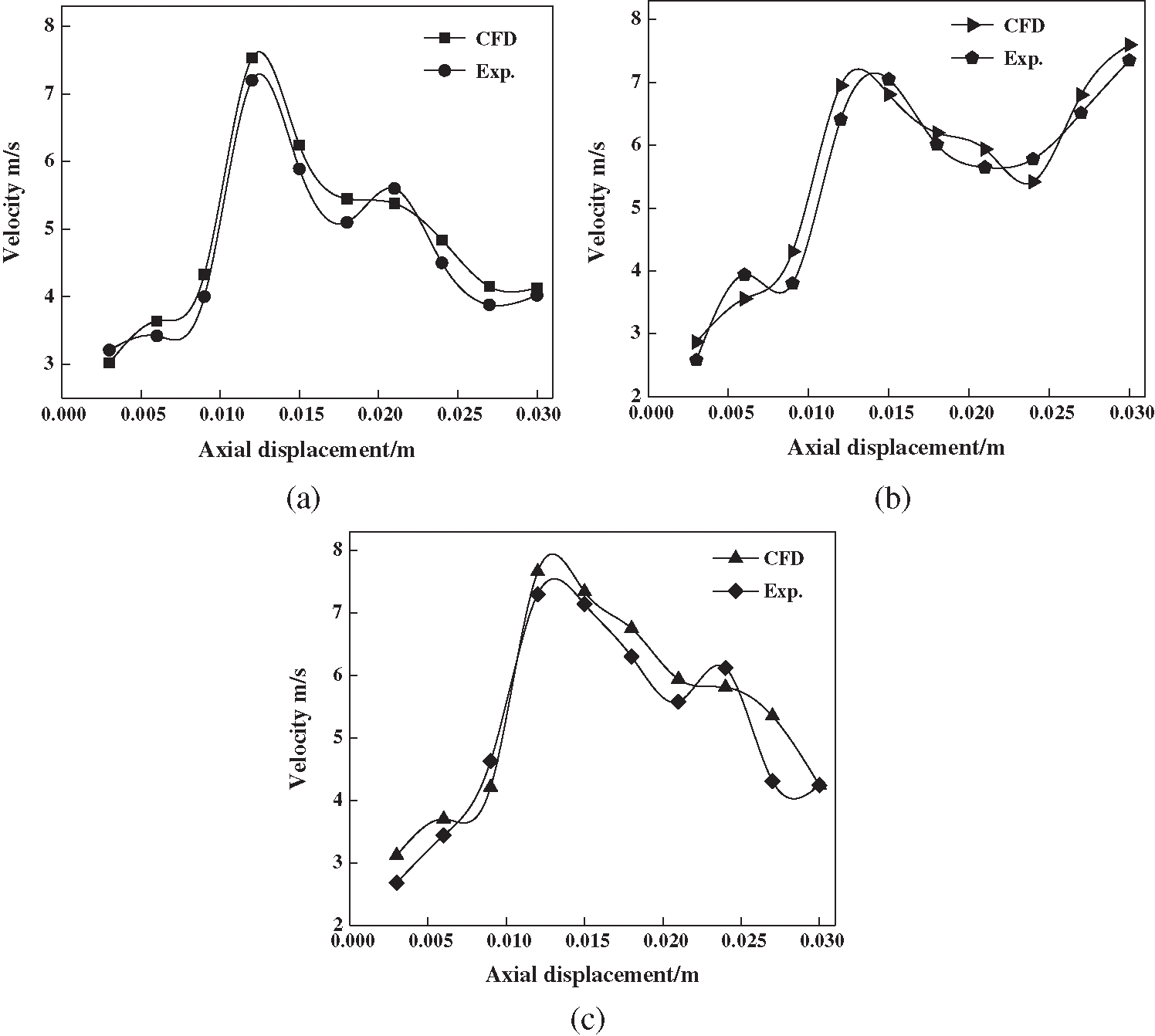
Figure 16: Analysis of internal velocity of nozzles with different orifice shapes (a) Cylindrical nozzle (b) Contraction conical nozzle (c) Expansion conical nozzle
(3) Micromorphology of Si3N4 particles
The micromorphology of Si3N4 particles corresponding to three nozzles with different orifice shapes is observed by scanning electron microscopy. The micromorphology of Si3N4 particles corresponding to three nozzles with different orifice shapes is shown in Fig. 17. The atomization effect of nozzles with different orifice shapes can be indirectly reflected by the diameter of Si3N4 particles prepared by dry granulation because the composition of Si3N4 particles includes atomized droplets and Si3N4 powder, in which the proportion of atomized droplets is very important. The weight of three stacks of Si3N4 powder is measured by electronic scale, making that the weight of each stack of Si3N4 powder is equal, which ensures that the proportion of Si3N4 powder in Si3N4 particles corresponding to each nozzle is almost equal, so the size of Si3N4 particles can indirectly reflect the size of atomized droplets sprayed by each nozzle. It can be seen from that the Si3N4 particles corresponding to contraction conical nozzle are smaller than those of cylindrical nozzle and expansion conical nozzle generally, which indirectly reflects the smallest diameter of atomized droplets sprayed by contraction conical nozzle, indicating that the atomization effect of contraction conical nozzle is the best, and it further verifies the correctness of numerical simulation.
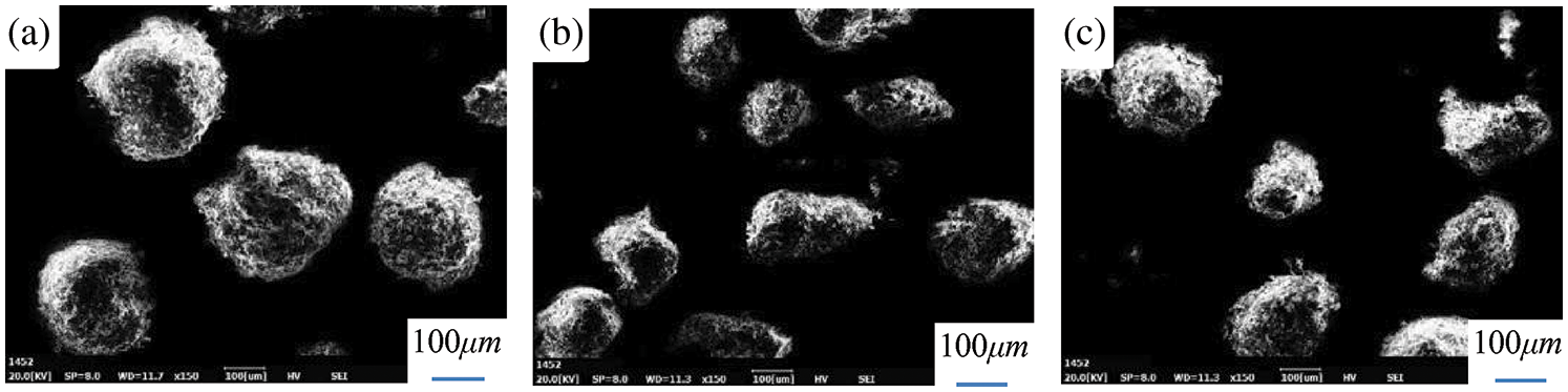
Figure 17: Micromorphology of Si3N4 particles (a) Cylindrical nozzle (b) Contraction conical nozzle (c) Expansion conical nozzle
(1) Based on VOF method, the dynamics between air and liquid two-phase flow in three kinds of nozzles with different orifice shapes for Si3N4 dry granulation is analyzed. The three-dimensional flow field in three nozzles with different orifice shapes is calculated by using the modified realizable k-ε turbulence model. The effects of orifice shapes on velocity distribution, pressure distribution are analysed. The atomization experiment platform is designed and the experimental results are in good agreement with the results of numerical simulation, which verifies the correctness of numerical simulation. This method can provide theoretical guidance for the analysis of the flow field of a nozzle for Si3N4 dry granulation.
(2) Compared with cylindrical nozzle and expansion conical nozzle, the pressure consumption in the swirl chamber of contraction conical nozzle is the smallest under the same conditions, and the pressure difference between the internal and external environment of nozzle is larger, so that the air from outside is sucked back into nozzle. Because of the large air core formed in contraction conical nozzle, the spray cone angle at nozzle orifice is the largest. In addition, the thickness of liquid film formed by the straight section at the orifice of contraction conical nozzle is the smallest, and the velocity at the orifice of the nozzle is the largest. Considering the performance of nozzles, the contraction conical nozzle is more suitable for the atomization of Si3N4 dry granulation in practical production. The conclusion can provide a theoretical reference for the structural optimization and design of a nozzle for Si3N4 dry granulation.
Acknowledgement: The authors acknowledge the National Natural Science Foundation of China (Grant: 51964022).
Funding Statement: This work was supported by National Natural Science Foundation of China [Grant No. 51964022].
Conflicts of Interest: The authors declare that they have no conflicts of interest to report regarding the present study.
1. Liao, D. H., Zhu, Z. X., Wu, N. X., Yu, D. L., Chen, T. (2017). Effect of blank particles forming and atomized liquid content on dry granulation process. Journal of Synthetic Crystals, 46(8), 1442–1449. [Google Scholar]
2. Kruisz, J., Rehrl, J., Sacher, S., Aigner, I., Horn, M. et al. (2017). RTD modeling of a continuous dry granulation process for process control and materials diversion. International Journal of Pharmaceutics, 528(1–2), 334–344. DOI 10.1016/j.ijpharm.2017.06.001. [Google Scholar] [CrossRef]
3. Mangal, H., Kirsolak, M., Kleinebudde, P. (2016). Roll compaction/dry granulation: Suitability of different binders. International Journal of Pharmaceutics, 503(1–2), 213–219. DOI 10.1016/j.ijpharm.2016.03.015. [Google Scholar] [CrossRef]
4. Liu, J., Qin, Q., Yu, Q. (2020). The effect of size distribution of slag particles obtained in dry granulation on blast furnace slag cement strength. Powder Technology, 362(C), 32–36. DOI 10.1016/j.powtec.2019.11.115. [Google Scholar] [CrossRef]
5. Chinn, J. J., Cooper, D., Yule, A. J., Nasr, G. G. (2016). Stationary rotary force waves on the liquid-air core interface of a swirl atomizer. Heat and Mass Transfer, 52(10), 2037–2050. DOI 10.1007/s00231-015-1706-0. [Google Scholar] [CrossRef]
6. Shatrov, M. G., Malchuk, V. I., Dunin, R. Y. (2020). A laboratory investigation into the fuel atomization process in a diesel engine for different configurations of the injector nozzles and flow conditions. Fluid Dynamics and Materials Processing, 16(4), 747–760. DOI 10.32604/fdmp.2020.08991. [Google Scholar] [CrossRef]
7. Som, S. K. (2012). Air core in pressure swirl atomizing nozzles. Atomization and Sprays, 22(4), 283–303. DOI 10.1615/AtomizSpr.2012005174. [Google Scholar] [CrossRef]
8. Su, C., Zheng, Q., Zhao, W. (2020). A combined experimental and numerical study of shotcrete jets and related wet spray nozzles. Fluid Dynamics & Materials Processing, 16(5), 947–960. DOI 10.32604/fdmp.2020.09676. [Google Scholar] [CrossRef]
9. Amini, G. (2016). Liquid flow in a simplex swirl nozzle. International Journal of Multiphase Flow, 79(4), 225–235. DOI 10.1016/j.ijmultiphaseflow.2015.09.004. [Google Scholar] [CrossRef]
10. Broniarz-Press, L., Włodarczak, S., Matuszak, M., Ochowiak, M., Idziak, R. et al. (2016). The effect of orifice shape and the injection pressure on enhancement of the atomization process for pressure-swirl atomizers. Crop Protection, 82(5), 65–74. DOI 10.1016/j.cropro.2016.01.005. [Google Scholar] [CrossRef]
11. Li, Y. (2020). Analyzing the flow field in the oil chamber of a hydrostatic guide rail used for ultra-precision machining: Numerical simulation and performance optimization. Fluid Dynamics & Materials Processing, 16(6), 1129–1145. DOI 10.32604/fdmp.2020.09437. [Google Scholar] [CrossRef]
12. Boroujerdi, A. N., Kebriaa, A. (2015). Numerical simulation of laminar and turbulent two-phase flow in pressure-swirl atomizers. AIAA Journal, 50(10), 2091–2101. DOI 10.2514/1.J051331. [Google Scholar] [CrossRef]
13. Mandal, A., Jog, M. A., Xue, J., Ibrahim, A. A. (2008). Flow of power-law fluids in simplex atomizers. International Journal of Heat and Fluid Flow, 29(5), 1494–1503. DOI 10.1016/j.ijheatfluidflow.2008.05.006. [Google Scholar] [CrossRef]
14. Jeong, J., Kim, C. N. (2007). A numerical simulation on diffuser-nozzle based piezoelectric micropumps with two different numerical models. International Journal for Numerical Methods in Fluids, 53(4), 561–571. DOI 10.1002/fld.1294. [Google Scholar] [CrossRef]
15. Horisawa, H., Sawada, F., Onodera, K., Funaki, I. (2008). Numerical simulation of micro-nozzle and micro-nozzle-array flow field characteristics. Vacuum, 83(1), 52–56. DOI 10.1016/j.vacuum.2008.03.097. [Google Scholar] [CrossRef]
16. Ronny, Y. S. C., Hisham Amirnordin, S., Mansor, N., Khalid, A. (2015). Numerical analysis of nozzle hole shape to the spray characteristics from premix injector in burner system: A review. Applied Mechanics and Materials, 773–774, 610–614. DOI 10.4028/www.scientific.net/AMM.773-774.610. [Google Scholar] [CrossRef]
17. Ronny, Y. S. C., Hisham Amirnordin, S., Khalid, A. (2015). Effects of nozzle shape on the flow characteristics of premix injector using computational fluid dynamics (CFD). Applied Mechanics and Materials, 773–774, 450–454. DOI 10.4028/www.scientific.net/AMM.773-774.450. [Google Scholar] [CrossRef]
18. Mund, C., Thatoi, D. N., Sahoo, S. (2016). Effect of nozzle shape on solidification behaviour in high-speed twin-roll strip caster: A simulation approach. Advances in Materials & Processing Technologies, 2(3), 10. [Google Scholar]
19. Macías-Hernández, M. J., Dávila-Maldonado, O., Guzmán-Vargas, A., Sotelo-Boyás, R., Zarazua-Villalobos, L. (2016). CFD simulation of interfacial instability from the nozzle in the formation of viscous core-annular flow. Canadian Journal of Chemical Engineering, 94(10), 2004–2012. DOI 10.1002/cjce.22580. [Google Scholar] [CrossRef]
20. Belhadef, A., Vallet., A., Amielh, M., Anselmet, F. (2012). Pressure-swirl atomization: Modeling and experimental approaches. International Journal of Multiphase Flow, 39(9), 13–20. DOI 10.1016/j.ijmultiphaseflow.2011.09.009. [Google Scholar] [CrossRef]
21. Vallet, A., Belhadef, A. (2013). Atomization modelling: A Eulerian approach. Ist International Symposium on CFD Applications in Agriculture, 1008(4), 45–50. [Google Scholar]
22. Jia, M., Xie, M., Liu, H., Lam, W. H., Wang, T. (2011). Numerical simulation of cavitation in the conical-spray nozzle for diesel premixed charge compression ignition engines. Fuel, 90(8), 2652–2661. DOI 10.1016/j.fuel.2011.04.017. [Google Scholar] [CrossRef]
23. Lefebvre, A. H., Wang, X. F. (1987). Mean drop sizes from pressure-swirl nozzles. Journal of Propulsion and Power, 3(1), 11–18. DOI 10.2514/3.22946. [Google Scholar] [CrossRef]
24. Laryea, G. N., No, S. Y. (2003). Development of electrostatic pressure-swirl nozzle for agricultural applications. Journal of Electrostatics, 57(2), 129–142. DOI 10.1016/S0304-3886(02)00122-5. [Google Scholar] [CrossRef]
25. Wang, X. F., Lefebvre, A. H. (2013). Atomization performance of pressure-swirl nozzles. Atomization & Sprays, 4(3), 351–367. [Google Scholar]
26. Vijay, G. A., Nsv, M., Manivannan, A. (2015). Internal and external flow characteristics of swirl atmizers: A review. Atomization and Sprays, 25(2), 153–188. DOI 10.1615/AtomizSpr.2014010219. [Google Scholar] [CrossRef]
27. Alkhedhair, A., Jahn, I., Gurgenci, H., Guan, Z. Q., He, S. Y. et al. (2016). Numerical simulation of water spray in natural draft dry cooling towers with a new nozzle representation approach. Applied Thermal Engineering, 98(3), 924–935. DOI 10.1016/j.applthermaleng.2015.10.118. [Google Scholar] [CrossRef]
28. Hirt, C. W., Nichols, B. D. (1981). Volume of fluid (VOF) method for the dynamics of free boundaries. Journal of Computational Physics, 39(1), 201–225. DOI 10.1016/0021-9991(81)90145-5. [Google Scholar] [CrossRef]
29. Lan, Z. K., Zhu, D. H., Tian, W. X., Su, G. H., Qiu, S. Z. (2014). Numerical approaches and analysis of spray characteristics for pressuriser nozzles. Canadian Journal of Chemical Engineering, 92(5), 953–963. DOI 10.1002/cjce.21911. [Google Scholar] [CrossRef]
30. Zhong, M. J., Zhou, Y. S., Lin, M., Xiong, J. B., Yang, Y. H. (2017). Numerical simulation of molten jet breakup by coupled multiphase model based on vof method and two-fluid model. Hedongli Gongcheng/Nuclear Power Engineering, 38(3), 12–17. [Google Scholar]
31. Fuster, D., Anne, B., Boeck, T., Moyne, L. L., Leboissetier, A. et al. (2009). Simulation of primary atomization with an octree adaptive mesh refinement and VOF method. International Journal of Multiphase Flow, 35(6), 550–565. DOI 10.1016/j.ijmultiphaseflow.2009.02.014. [Google Scholar] [CrossRef]
 | This work is licensed under a Creative Commons Attribution 4.0 International License, which permits unrestricted use, distribution, and reproduction in any medium, provided the original work is properly cited. |