DOI: 10.32604/fdmp.2021.011062
ARTICLE
Design and Optimization of a Hybrid Energy System for Decentralized Heating
1China Electric Power Research Institute, Beijing, 100192, China
2State Key Laboratory of Power Grid Safety and Energy Conservation, Beijing, 100192, China
3School of Environmental Science and Engineering, Tianjin University, Tianjin, 300350, China
*Corresponding Author: Ling Cheng. Email: 0707126416@163.com
Received: 17 April 2020; Accepted: 09 October 2020
Abstract: The performances of a hybrid energy system for decentralized heating are investigated. The proposed energy system consists of a solar collector, an air-source heat pump, a gas-fired boiler and a hot water tank. A mathematical model is developed to predict the operating characteristics of the system. The simulation results are compared with experimental data. Such a comparison indicates that the model accuracy is sufficient. The influence of the flat plate solar collector area on the economic and energy efficiency of such system is also evaluated through numerical simulations. Finally, this system is optimized using the method of orthogonal design. The results clearly demonstrate that the solar-heat pump-gas combined system is more convenient and efficient than the simple gas system and the heat pump-gas combined system, whereas it is less convenient but more efficient than the solar-assisted gas system.
Keywords: Hybrid energy system; mathematical model; system optimization; annual performance factor
Space heating takes a great proportion of global energy consumption [1]. About 40% of the non-renewable energy are consumed to meet the thermal needs of buildings [2–4]. With the improvement of living standards, the heating demands in the areas without central heating are growing. Most of the conventional space heating and hot water supplying system in these areas consume fossil energy, which are not friendly to the environment for the emission of air pollutants, as well as thicken the smog weather. Hybrid renewable energy system is an effective way to deal with the conflict between the environment and resources.
A large number of investigations have been performed to study the performance of hybrid energy heating system. Among the renewable energy sources that can be used, solar thermal energy is considered to be one of the most efficient and environmental friendly energy form [5,6]. Lots of studies have focused on the usage of solar energy for covering heating needs in the residential buildings. Badescu et al. [7] examined the performance of an active solar heating system in a passive building. Air-source heat pump (ASHP) was widely used in the domestic buildings for heating because of their high-efficiency and energy-saving [8]. Practical studies have shown the potential of ASHP to drastically reduce the CO2 emissions and improve air quality [9]. Solar-assisted heat pump (SAHP) systems combined solar thermal collectors and heat pumps, which improved the solar fraction and reduced the fossil energy consumption. Chu et al. [10] conducted a review of a wide variety of SAHP system, and the results indicated that the performance of SAHP systems were much higher than the simple system, but the performance was difficult to evaluate for the variety of system construction. Chandrashekar et al. [11] developed a simplify model to analyze the performance of SAHP, and it revealed that the system efficiency was higher for multiplex dwellings than single-family dwellings. Panaras et al. [12] established a numerical model for SAHP and it indicated that the SAHP could save about 70% of auxiliary energy usage in comparison to an electric hot water tank. Banister et al. [13] studied the performance of a dual tank solar-assisted heat pump system, and the results demonstrated that the dual tank SAHP system increased energy savings from 60% to 69% for 7.5 m2 solar collector in comparison to a traditional solar domestic hot water system. Li et al. [14] developed a mathematical model of the solar assisted air source heat pump systems for hot water production to predict its operation performance under specified weather conditions. The system performance was influenced by various parameters, which was governed strongly by the variety of circulation flow rate, solar collector area and initial water temperature in the preheating solar tank. Hatheway et al. [15] used the return rate and life cycle critical price to analyze the economic feasibility of SAHP systems, which indicated that the operation strategy varies with the variety of electricity price. Ozgener [16] has studied the application of solar assisted geothermal heat pump combined with a small wind turbine for covering the heating and cooling needs of agricultural and residential buildings. Huang et al. [17] firstly proposed the design of integral-type solar-assisted heat pump system, which integrated the heat pump, solar collector and water storage tank into a single unit. Scarpa et al. [18] proposed solar-assisted heat pumps for water heating and coupled to gas system (ISAPH), which showed that the ISAHP system had higher thermal efficiency compared to flat plate solar collector. Chyng et al. [19] estimated a modeling and system simulation of an ISAHP water heater. The simulation results for instantaneous performance agreed very well with the experimental data and the model was used to analyze the daily performance of the ISAHP for 1 year. It is shown that the daily COP was around 1.7 to 2.5 for the ISAHP. Huang et al. [20] experimentally studied the instantaneous performance of an ISAHP, and it showed that an automatic control system of the expansion valve might be required for the ISAHP. Tamvakidis et al. [21] presented an experimental study on the energy performance of hybrid solar heating system for farrowing houses. The results confirmed that around 70% of the heating needs could be supplied by the system during the warm period, while the achieved energy saving was approximately 25%~30% during the cold period. Kiyan [22] proposed a mathematical method to simulate the thermal property of a hybrid solar heating system. The numerical results showed that the hybrid system had high thermal efficiency and greatly reduced the pollutant emissions.
In view of this, this study proposes a hybrid energy system which combines solar collector, heat pump and gas-fired boiler to satisfy the heating needs of the users. The system performance is predicted and optimized through a mathematical model which is verified by the experimental data. The effects of key parameters on the system performance are studied with model. The study has significance in the energy cascade utilization and energy saving compared with the traditional heating supply systems.
A mathematical model is developed based on the coupled models of different components, including the models of solar collector, heat pump, gas-fired boiler and storage tank. In order to simulate the operation of each unit, the models of heating units are established by several simple models. The heat storage tank is the key component of the system, which adopts hierarchical non-steady state mathematical model to reflect the relationship between the heating unit and heating supply unit.
2.1 Mathematical Model of Solar Collector
The heat gains of solar collector can be calculated as follows:

The incident solar radiation on a tilted surface (Iθ) can be estimated as follows:

while Rb can be calculated by:

The declination, δ can be calculated from:

where m is the mth day of a year.
2.2 Mathematical Model of Air-Source Heat Pump
Air-source heat pump mainly consists of four parts: Evaporator, compressor, condenser and expansion valve. In order to calculate the power consumption of compressor and the heat release of condenser, the model of air-source heat pump is established. State points distribution of refrigerant are shown in Fig. 1.
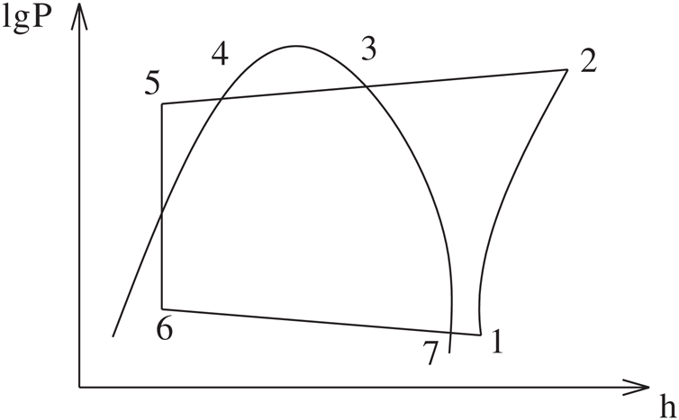
Figure 1: State points distribution of refrigerant
As can be seen in Fig. 2 that the evaporation temperature t6 can be expressed as:  , P6 is evaporation pressure, P1 can be expressed as:
  , temperature of the refrigerant at compressor inlet t1 can be expressed as:
  , the condensing temperature t4 can be expressed as:
 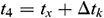 , P4 is the condensing pressure, P2 can be expressed as:
 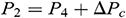 , t5 can be expressed as:
  .
.
The model of compressor is developed by the method of polytropic exponent. The operation of compressor can be calculated according to the following relations:
Refrigerant mass flow rate of compressor can be calculated as follows:

Theoretical power consumption by compressor can be represented as follows:

Input power of compressor motor can be evaluated as follows:

Discharge temperature of compressor can be estimated as follows:

Thermal energy provided by heat pump can be calculated as follows:

The COP of heat pump can be obtained according to:

The thermodynamic properties calculation of refrigerant runs several times during the simulation, and the Cleland correlation formula is introduced to establish the refrigerant properties.
According to the schematic of heat pump and the thermophysical parameters of each point calculated by Cleland correlation formula, the heat pump model is built according to the following equations:
Evaporator function

Compressor function

Condensator function

Expansion valve function

According to these mathematical formulas, the enthalpy value of each state point can be calculated. The power consumption and heat release of the heat pump can be obtained according to the compressor model. The heat pump model solution flow chart is demonstrated in Fig. 2.
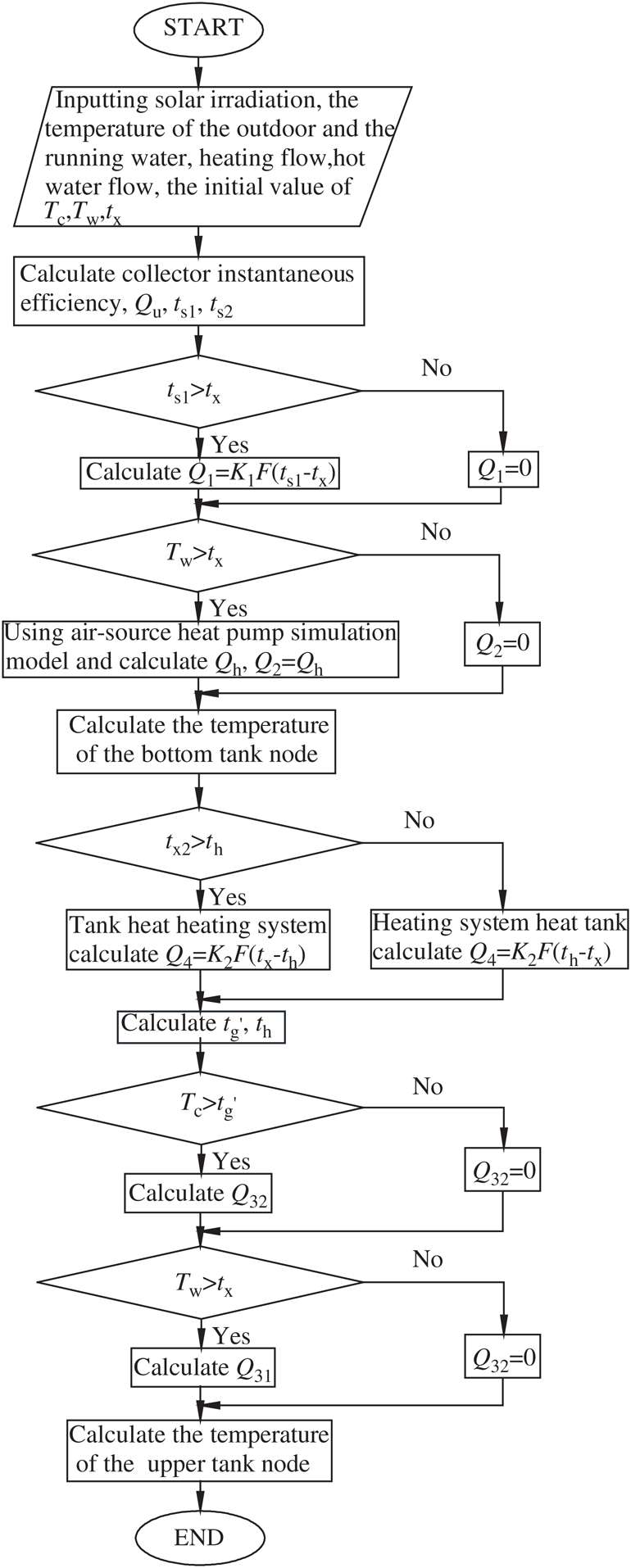
Figure 2: Heat pump model solution flow chart
2.3 Mathematical Model of the Gas-Fired Boiler
The gas-fired boiler is to heat the supply hot water when the water temperature at the upper tank (tx2) cannot reach the required temperature TW (i.e., 50°C). The gas-fired boiler is also used to increase the supply temperature of heating system from the tank when it cannot reach the required temperature TC (i.e., 45°C).
The expression of gas consumption can be evaluated as follows:

where Q31 and Q32 can be estimated as follows:


2.4 Mathematical Model of Heat Storage Tank
In practical application, the thermal stratification phenomena of heat storage tank is serious. In order to calculate the temperature in the tank accurately, the model of heat storage tank is established by the distributed parameter method and the heat storage tank is divided into two segments along the vertical direction.
In order to establish the mathematical model conveniently and solve it easily, the following assumptions are made: (1) Ignore the heat loss of heat storage tank; (2) Ignore the heat loss of system pipeline.
Unsteady state thermal equations of the tank are described based on energy balance and solved by the software of Matlab. The schematic of heat storage tank is as follows:
Figure 3: The schematic of heat storage tank. (a) The schematic of the tank, (b) Upper node schematic of the tank and (c) Bottom node schematic of the tank
Schematic of the bottom tank is shown in Fig. 3b. The solar collectors and heat pump are used for heating the heat storage tank bottom and the running water absorbs heat from the bottom part of the tank and flows to the upper part.
The energy balance equations for the bottom segment of the tank can be represented as follows:

Q1 is the thermal energy provided by the bottom heat exchange coil and it can be calculated as follows:

Average logarithmic temperature difference Δtm1 can be calculated as follows:

And Q1 can also be represented as follows:

The energy balance equations for the bottom heat exchange coil can be estimated as follows:

The schematic of the upper tank is illustrated in Fig. 3c. The heating system heats the water of tank when th is higher than tx2. The energy balance equations for the upper segment are shown as follows:


The thermal energy provided by the upper heat exchange coil Q4 can be represented as follows:

The average logarithmic temperature difference Δtm2 can be calculated as follows:
Q4 can also be represented as follows:


The energy balance equations for the upper heat exchange coil can be estimated as follows:


The thermal energy provided to the heating system by gas-fired boiler Q32 can be calculated as follows:

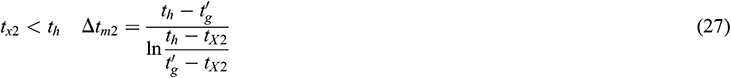
The stratified model solution flow chart is illustrated in Fig. 4.
Figure 4: The stratified model solution flow chart
2.5 The Model of Hybrid Energy System
The hybrid energy system model solution flow is demonstrated in Fig. 5.
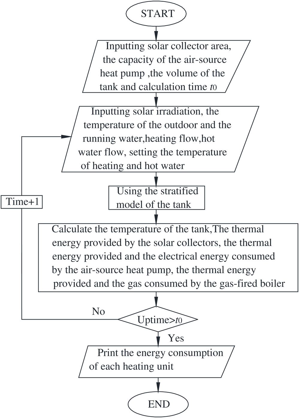
Figure 5: The system model solution flow chart
In order to give a comprehensive evaluation of the hybrid energy system, the performance index and economical index are proposed in this paper.
Annual performance factor is the performance index of the system, which refers to the ratio of total heat provided by the system to the primary energy consumption and it can be calculated as follows:

The annual cost is the economical index, which includes the initial investment and operation costs, and it can be calculated as follows:

The initial investment (C0) includes the cost of flat plate solar collector (C1), air-source heat pump (C2), gas-fired boiler (C3), heat storage tank (C4) and system fixed initial investment (Cm), including water pumps, valves, piping et al. It can be calculated as follows:

The operation costs considers the electricity consumption of solar system (Wt) and heat pump (Wh), gas consumption of gas-fired boiler (Vg). It can be estimated as follows:

3 Experimental System and Verification
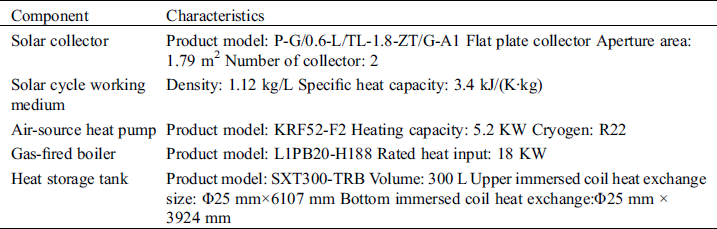
In order to verify the accuracy of the mathematical model, a prototype of the hybrid system is built. The structure of the hybrid energy system is illustrated in Fig. 6a. The hybrid energy system for decentralized heating consists of three heating units, which are solar energy heating unit, air-source heat pump heating unit and gas-fired boiler heating unit, and a heat storage tank unit.
The heat storage tank is the connecting link of the three heating units, which is the core component of the whole system. Therefore, the temperature distribution of the tank has important influence on the thermal performance of the whole system and plays an important role in improving the economic and energy efficiency.
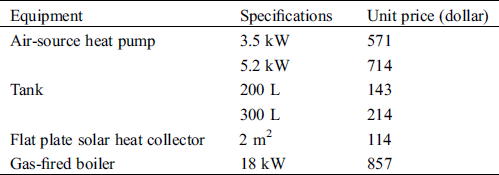
The lay-out of the experimental system is presented in Fig. 6b. The collectors are oriented to the south with the tilt angle of 30°. The technical characteristics of the main components are presented in Tab. 1.
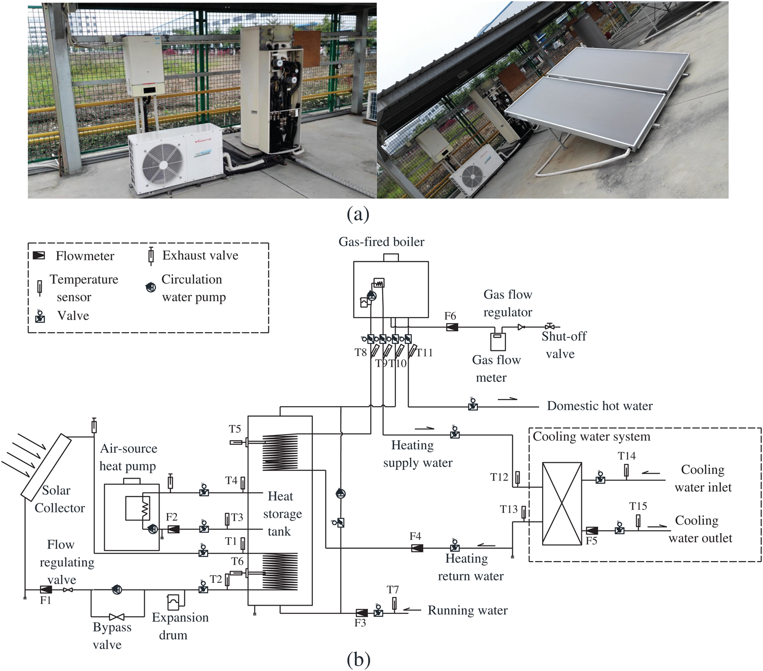
Figure 6: (a) Experimental hybrid energy system. (b) Hybrid energy system test schematic
Table 1: Technical characteristics of main components
The solar radiation intensity (with an accuracy of ±2%), the ambient wind speed (with an accuracy of ±(0.3 + 0.03) m/s) and the ambient temperature (with an accuracy of ±0.1°C) were measured by a meteorological station. Temperatures were measured by Pt100 thermocouples with an accuracy of ±0.1°C. Mass flow rate was measured by turbine flow meter and electromagnetic flow meter (with an accuracy of ±1%). Electricity consumption was measured by electricity meter (with an accuracy of ±1%). The type and position of the measuring instruments are presented in Tab. 2.
Table 2: Type and position of measuring sensors
The thermal power provided by the solar collectors (Qtt), heat pump (Qht) and gas-fired boiler (Qrt) in this experimental system were calculated on the basis of the measured individual quantities, according to the relation as follows:


Experiments were conducted from 7:00 AM to 19:00 PM during the period of August 22nd~September 5th. The heating water and domestic hot water supply temperature are set to be 50°C. The data is recorded per minute automatically. Fig. 7 shows part of the monitored environmental condition values, including the ambient air temperature and wind speed during the period of tests. The ambient air temperature varied from 28.2°C to 36.1°C. The solar radiation intensity varied from 0 to 1200 W/m2. The wind speed fluctuated with time and ranged from 0 to 2.8 m/s.
The hot water daily load of the tested system is 56511 kJ and the heating load is 172553 kJ. According to the test results, the heat transfer coefficient of the upper coil is 870 W/(m2·K) while it is 940 W/(m2·K) for the tank bottom.
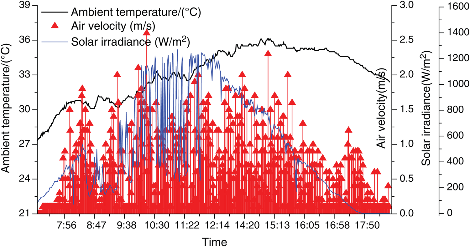
Figure 7: Environmental conditions during the tests
Fig. 8 shows comparison between the measured and simulated water temperature for the tank bottom. It shows that the experimental and simulated results agree well with each other. The average deviation of working fluid temperature at solar collector inlet is 3.18°C (7.47%) while the maximum one is 7.67°C (17.1%). The average deviation of working fluid temperature at solar collector outlet is 3.29°C (8.42%) while the maximum one is 9.89°C (21.3%). The average deviation of the water temperature at the tank bottom is 1.74°C (4.38%) while the maximum one is 7.66°C (19.8%). The deviation is acceptable and the model is considered to be accuracy enough for further analysis.
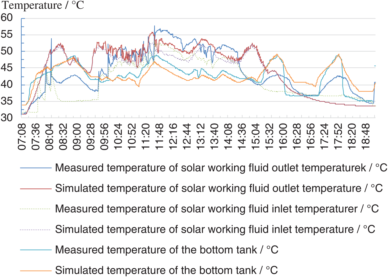
Figure 8: Measured and simulated temperature for the tank bottom
Comparison between the measured and simulated upper tank water temperature is conducted and the results are illustrated in Fig. 9. It shows that the trends of the experimental and simulated results are the same. The average deviation of the heating water supply temperature from the tank is 1.61°C (3.85%) while the maximum one is 7.58°C (17.1%). The average deviation of the heating water temperature return to the tank is 2.25°C (5.64%) while the maximum one is 7.34°C (19.5%). The average deviation of the water temperature at the upper tank is 2.85°C (5.78%) while the maximum one is 6.53°C (13.4%). The deviation is considered to be acceptable in this study.
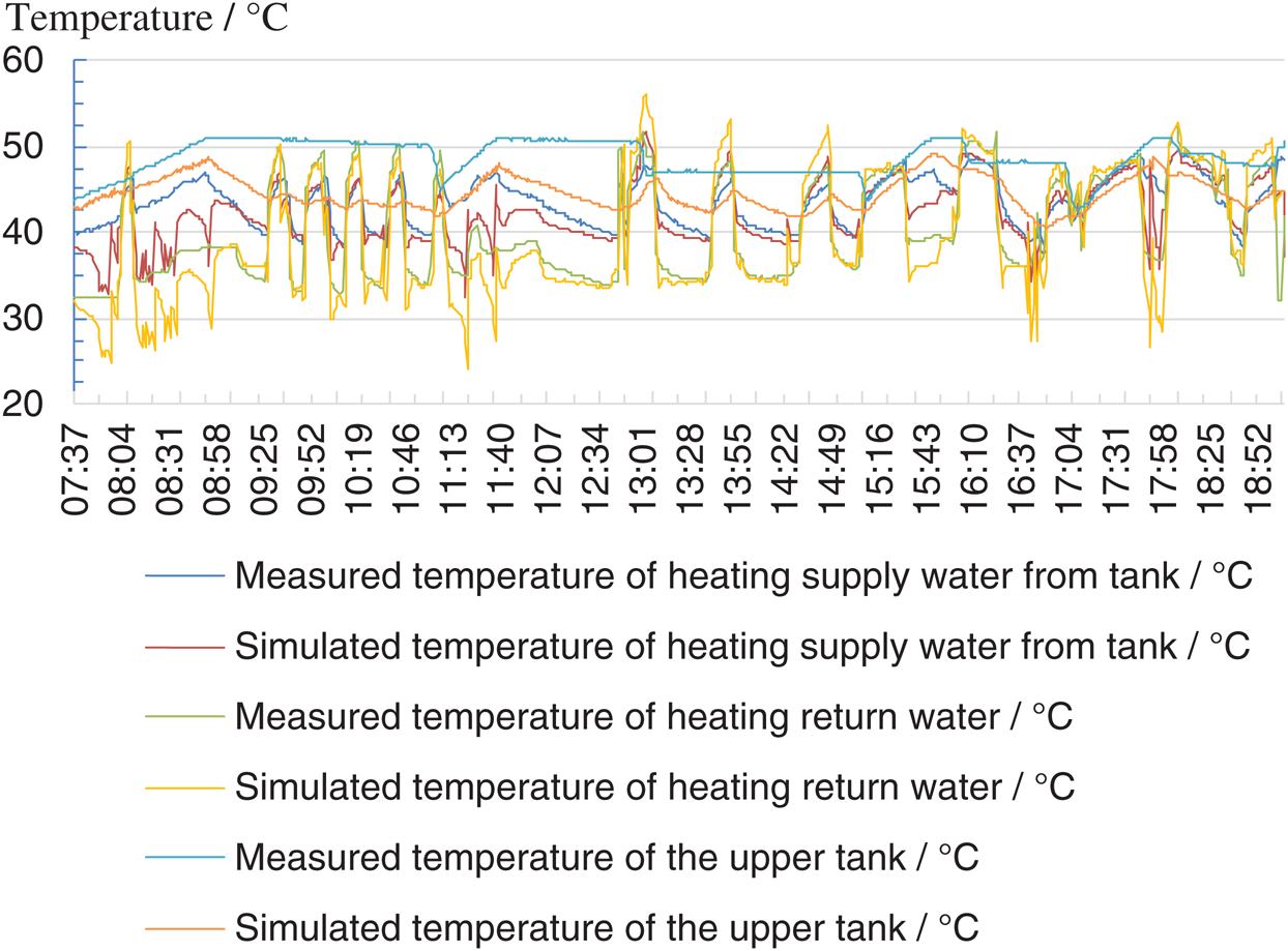
Figure 9: Measured and simulated temperature of the upper tank
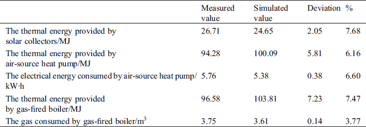
Tab. 3 shows comparison between the measured and simulated thermal energy and the energy consumed by the heating units. The deviation of thermal energy provided by solar collectors is 2.05 MJ (7.68%), while it is 5.81 MJ (6.16%) for air-source heat pump and 7.23 MJ (7.47%) for gas-fired boiler. The deviation of electrical energy consumed by air-source heat pump is 0.38 kW·h (6.60%), and it is 0.14 m3 (3.77%) for gas consumed by gas-fired boiler. Therefore, the deviation is considered to be acceptable.
Table 3: Measured and simulated value of the heating units
The influence of flat plate solar collector area on the hybrid energy system performance, system optimization and comparison with other systems are investigated based on the model. The annual comprehensive energy efficiency ratio and annual cost are considered to evaluate the hybrid energy system. A residential site for 3 people living with the total area of 105.16 m2 is studied to evaluate the performance of the hybrid energy system.
Domestic hot water load and heating load are the key parameters in this study and the domestic hot water load can be calculated as follows:

where n is the user number of hot water and it is 3 in this study, qr is the water consumption per person and the value is 80 L, tr is the temperature of hot water and it is 60°C, tL is the temperature of cold water and it is 20°C.
Hourly hot water load can be estimated as follows:

where Kh is proportional parameter and the results are given in Fig. 10.
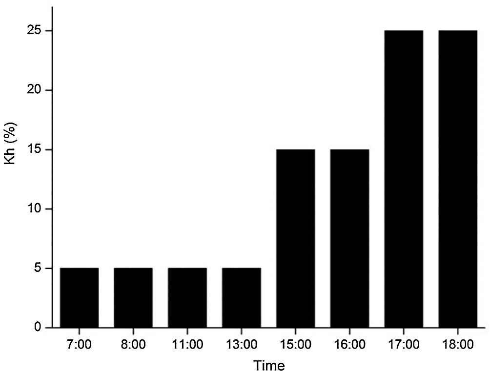
Figure 10: Value of Kh
Heating load of the residential site is calculated by eQuest, and the results are shown in Fig. 11.
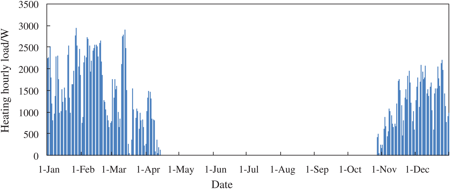
Figure 11: Heating load of the residential site
According to the results, the maximum hot water load is 2.791 kW, the maximum heating load is 2.8 kW and the total load is 10523.74 kJ.
The maximum area of solar collector Amax can be calculated as follows:

where Q is the maximum value of Qw and Qh, solar fraction f varies from 0.3 to 0.8; JT is the average daily solar radiation; the average collector efficiency  varies from 0.25 to 0.5; the heat loss rate of pipeline and heat storage tank
  varies from 0.2 to 0.3.
The maximum heat capacity of heat pump Qh max can be estimated as follows:

The maximum heat capacity of gas-boiled Qr max can be calculated as follows:

The volume of tank V can be represented as follows:

According to the heating demand, the specifications of the hybrid energy system are obtained, as shown in Tab. 4.
4.1 Effect of Flat Plate Solar Heat Collector Area
Figs. 12 and 13 are obtained under the conditions of tank volume is 300 L, the area of solar collector increases from 2 to 6 m2, the black line shows the variation of annual cost under the condition that the heat pump power rating is 5.2 kW. The red line shows the variation of the annual cost under the condition that the heat pump power rating is 3.5 kW.
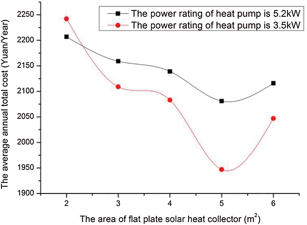
Figure 12: Effects of solar heat collector area on the annual cost
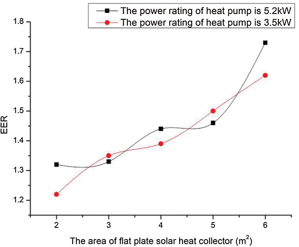
Figure 13: Effects of solar heat collector area on the annual performance factor
Figs. 12 and 13 presents the effect of flat plate solar heat collector areas on the hybrid energy system performance. As demonstrated in the figure, the e annual cost of the system firstly decreases (from 329 to 297 dollar in blue line, from 319 to 278 dollar in orange line) and then increases (from 297 to 302 dollar in blue line, from 278 to 292 dollar in orange line) with the increase of solar collector area from 1 to 6 m2. The minimum annual cost is obtained when the solar collector area is 5 m2. The annual comprehensive energy efficiency ratio increases (from 1.16 to 1.73 in blue line, from 1.2 to 1.62 in orange line). It can be attributed to the larger the solar collector area the more energy can be provided by solar, while the hot water and heating load remain constant.
4.2 Optimization of the System
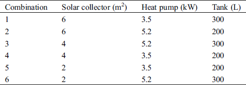
According to Eqs. (40) to (45), the solar collector area ranges from 0 to 13.3 m2, the power rating of air source heat pump ranges from 0 to 5.59 kW, the volume of water tank ranges from 0 to 1330 L. Considering the equipment models listed in Tab. 4, matching of each unit are as follows:
Factor A: The area of the solar collector in three levels: 2, 4, 6 m2.
Factor B: The power rating of the air source heat pump in two levels: 5.2, 3.5 kW.
Factor C: The volume of the water tank in two levels: 200, 300 L.
In order to optimize the hybrid energy system, orthogonal experiment method is employed to optimize combinations of each unit. The annual cost of the system under different combinations is simulated by the mathematical model and the optimization of the system can be obtained through the results listed in Tab. 5.
Table 5: The results of orthogonal design
According to Eq. (45), the volume of water tank in combination 3 is 300 L when the solar collector area is 6 m2. The schemes in Figs. 14a and 14b are simulated by the mathematical model to calculate the heat provided by each heating units, the annual cost (C) and the annual performance factor (EER) of the system. The results of each scheme are shown in Fig. 7.
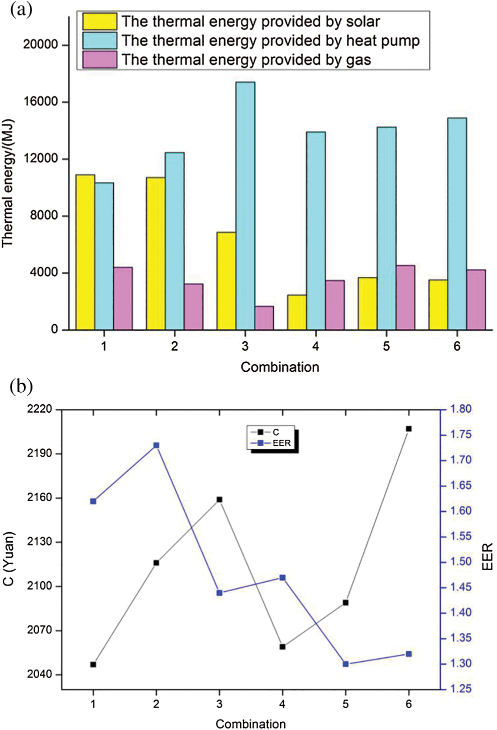
Figure 14: (a) The simulation results of thermal energy provided by each unit in different combinations. (b) The simulation results of C and EER in different combinations
Two optimum schemes are considered in this study, which are the minimum annual cost of the system and the annual comprehensive energy efficiency ratio.
Optimum scheme 1: Taking the minimum annual cost as the objective function and the optimized results are combination 1. The solar collector area is 6 m2, the power rating of air-source heat pump is 3.5 kW, the power rating of gas-fired boiler is 18 kW, the thermal storage tank is 300 L, the annual cost is 292 dollar and the annual comprehensive energy efficiency ratio is 1.62.
Optimum scheme 2: Taking the annual comprehensive energy efficiency ratio as the objective function and the optimized results are combination 2. The solar collector area is 6 m2, the power rating of air-source heat pump is 5.2 kW, the power rating of gas-fired boiler is 18 kW, the thermal storage tank is 300 L, the annual cost is 302 dollar and the annual comprehensive energy efficiency ratio is 1.73.
4.3 Comparison with Traditional Decentralized Heating System
The traditional decentralized heating system includes simple gas system, the heat pump-gas combined heating system and the solar-gas combined heating system. To compare the performance of the hybrid energy system and the traditional decentralized heating system, the optimal scheme of traditional decentralized heating system is conducted considering the annual cost and taking the energy efficiency as the objective function. The optimization schemes of the traditional decentralized heating systems are shown in Tab. 6. The simulation results are illustrated in Fig. 15.
Table 6: Optimization schemes of the traditional decentralized heating systems
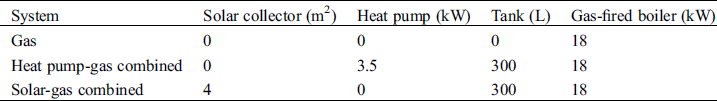
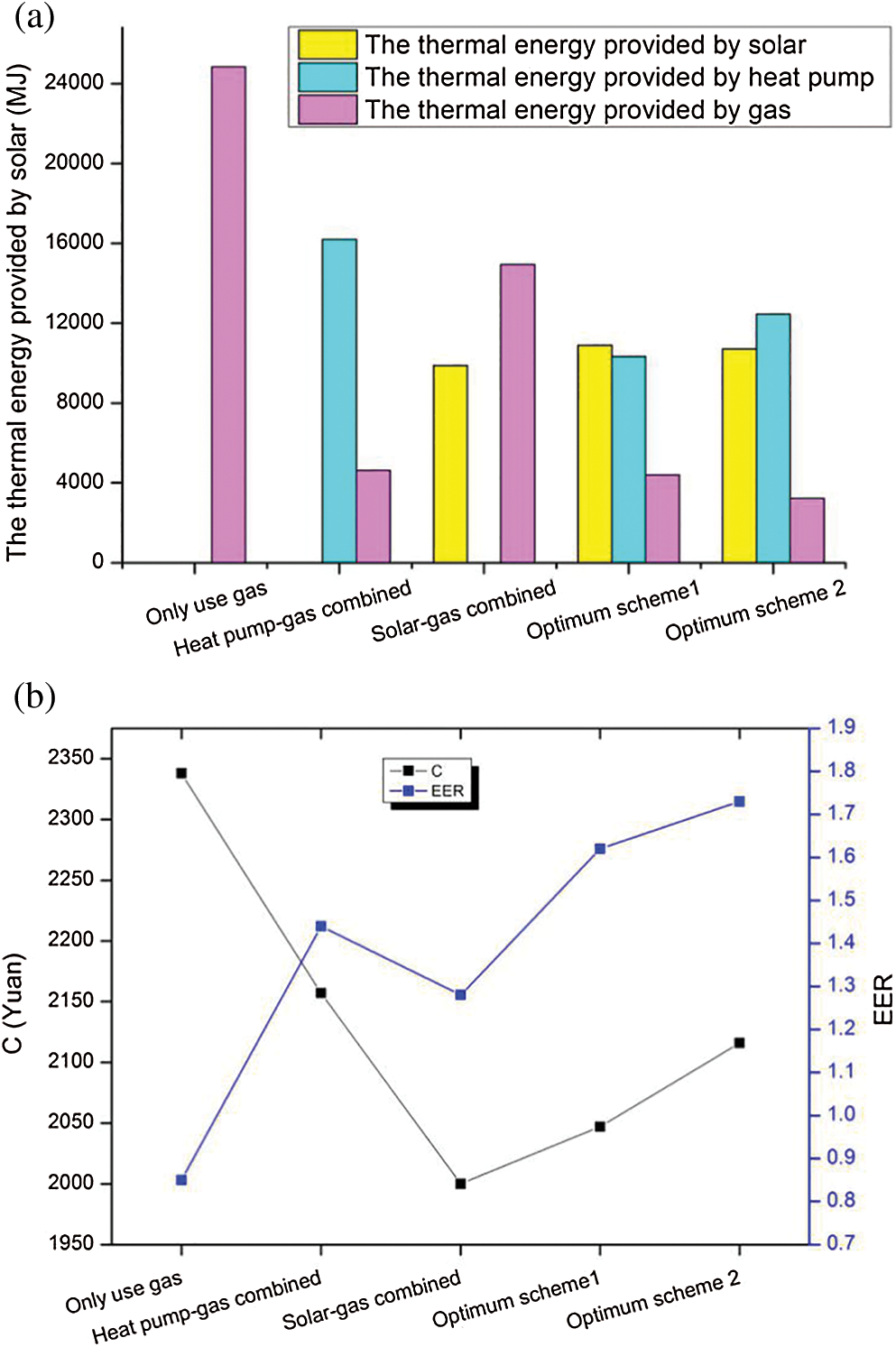
Figure 15: (a) Simulation results of thermal energy provided by each unit for traditional decentralized heating system. (b) Simulation results of C and EER for traditional decentralized heating system
In order to compare the economic performance of the systems, optimum scheme 1 is taken as the benchmark of the solar-heat pump-gas combined system. Compared with the hybrid energy system (C: 292 dollar, EER: 1.62), the annual cost of gas-fired system (334 dollar) increases by 14.22%, heat pump-gas combined system (308 dollar) rises by 5.37%, while solar-gas combined system (286 dollar) reduces by 2.35%. The annual comprehensive energy efficiency ratio of the simple gas system reduces by 0.77, heat pump-gas combined system reduces by 0.18, and the solar-gas combined system decreases by 0.34. The results show that the proposed hybrid system is more economical and efficient than the gas system and heat pump-gas combined system, while it is less economical but more efficient than solar-gas combined system.
In order to compare the system efficient, optimum scheme 2 is taken as the benchmark of solar-heat pump-gas combined system. Compared with the hybrid energy system (C: 302 dollar, EER: 1.73), the annual cost of gas system (334 dollar) rises by 10.49%, heat pump-gas combined system (308 dollar) increases by 1.94%, while the solar-gas combined system (286 dollar) reduces by 5.48%. The annual comprehensive energy efficiency ratio of gas system reduces by 0.88, heat pump-gas combined system decreases by 0.29, and the solar-gas combined system reduces by 0.45. The results show that the proposed hybrid system is more economical and efficient than the gas system and heat pump-gas combined system, while it is less economical but more efficient than the solar-gas combined system.
A hybrid energy system for decentralized heating is designed to satisfy the heating and domestic hot water demands. It makes the rational use of renewable energy and proposes an effective way to deal with the problems of environment and resource.
1. The numerical study indicates that different heating unit load capacity had strong effects on the system performance. The increase of flat plate solar heat collector area from 1 to 6 m2 results in an maximum increase in the annual comprehensive energy efficiency ratio of 0.57 and maximum decrease in the annual cost of 41 dollar.
2. Considering the economy of the system, the optimum result is that the solar collector area is 6 m2, the power rating of air-source heat pump is 3.5 kW, the power rating of gas-fired boiler is 18 kW, and the thermal storage tank is 300 L. Considering the efficiency of the system, the optimum result is that the solar collector area is 6 m2, the power rating of air-source heat pump is 5.2 kW, the power rating of gas-fired boiler is 18 kW, and the thermal storage tank is 300 L.
3. The research results indicate that the hybrid energy system contributes more to energy and economic saving than the traditional decentralized heating system. The simulation results show that compared with the gas system and heat pump-gas combined system, the proposed hybrid system is more economical and efficient. Compared with the solar-gas combined system,it is less economical but more efficient. The mathematical model is much helpful in the designing and optimizing of the hybrid system.
Science and technology project of state grid corporation-Research on demand response interaction strategy and simulation technology for integrated energy service business.
Funding Statement: Science and technology project of state grid corporation-Research on demand response interaction strategy and simulation technology for integrated energy service business.
Conflicts of Interest: The authors declare that they have no conflicts of interest to report regarding the present study.
1. Devanarayanan, K., Kalidasa Murugavel, K. (2014). Integrated collector storage solar water heater with compound parabolic concentrator—Development and progress. Renewable Sustainable Energy Reviews, 39, 51–64. DOI 10.1016/j.rser.2014.07.076. [Google Scholar] [CrossRef]
2. Zhang, B., Wang, Y., Zheng, J., Liu, D. (2020). Study on buildings CCHP system based on SOFC. Fluid Dynamics & Materials Processing, 16(3), 665–674. DOI 10.32604/fdmp.2020.09314. [Google Scholar] [CrossRef]
3. Ga, G., Groome, D. J. (1994). Thermal comfort models based on field measurements. ASHRAE Transactions, 100(1), 782–794. [Google Scholar]
4. Wang, X., Ni, P. (2020). An experimental investigation about the levels of PM2.5 and formaldehyde pollutants inside an office. Fluid Dynamics & Materials Processing, 16(2), 237–243. DOI 10.32604/fdmp.2020.09469. [Google Scholar] [CrossRef]
5. Choi, H. J., Kim, B. S., Kang, D., Kim, K. C. (2011). Defrosting method adopting dual hot gas bypass for an air-to-air heat pump. Applied Energy, 88(12), 4544–4555. DOI 10.1016/j.apenergy.2011.05.039. [Google Scholar] [CrossRef]
6. Feng, S., Xiong, D., Chen, G., Cui, Y., Che, P. (2020). Convection-diffusion model for radon migration in a three-dimensional confined space in turbulent conditions. Fluid Dynamics & Materials Processing, 16(3), 651–663. DOI 10.32604/fdmp.2020.07981. [Google Scholar] [CrossRef]
7. Zheng, W., Zhang, H., You, S., Ye, T. (2016). Numerical and experimental investigation of a helical coil heat exchanger for seawater-source heat pump in cold region. International Journal of Heat and Mass Transfer, 96, 1–10. DOI 10.1016/j.ijheatmasstransfer.2016.01.022. [Google Scholar] [CrossRef]
8. Wang, Z., Wang, F., Wang, X., Ma, Z. Wu, X. et al. (2017). Dynamic character investigation and optimization of a novel air-source heat pump system. Applied Thermal Engineering, 111, 122–133. DOI 10.1016/j.applthermaleng.2016.09.076. [Google Scholar] [CrossRef]
9. Chua, K. J., Chou, S. K., Yang, W. M. (2010). Advances in heat pump systems: A review. Applied Energy, 87(12), 3611–3624. DOI 10.1016/j.apenergy.2010.06.014. [Google Scholar] [CrossRef]
10. Zheng W., Ye T., You S., Zhang H., Zheng X. (2016). Experimental investigation of the heat transfer characteristics of a helical coil heat exchanger for a seawater-source heat pump. Journal of Energy Engineering, 142(1), 04015013. DOI 10.1061/(ASCE)EY.1943-7897.0000272. [Google Scholar] [CrossRef]
11. Panaras, G., Mathioulakis, E., Belessiotis, V. (2013). Investigation of the performance of a combined solar thermal heat pump hot water system. Solar Energy, 93, 169–182. DOI 10.1016/j.solener.2013.03.027. [Google Scholar] [CrossRef]
12. Banister, C. J., Collins, M. R. (2015). Development and performance of a dual tank solar-assisted heat pump system. Applied Energy, 149, 125–132. DOI 10.1016/j.apenergy.2015.03.130. [Google Scholar] [CrossRef]
13. Li, H., Yang, H. (2010). Study on performance of solar assisted air source heat pump systems for hot water production in Hong Kong. Applied Energy, 87(9), 2818–2825. DOI 10.1016/j.apenergy.2009.06.023. [Google Scholar] [CrossRef]
14. Hatheway, F. M., Converse, A. O. (1981). Economic comparison of solar-assisted heat pumps. Solar Energy, 27(6), 561–569. DOI 10.1016/0038-092X(81)90052-9. [Google Scholar] [CrossRef]
15. Ozgener, O. (2010). Use of solar assisted geothermal heat pump and small wind turbine systems for heating agricultural and residential buildings. Energy, 35(1), 262–268. DOI 10.1016/j.energy.2009.09.018. [Google Scholar] [CrossRef]
16. Huang, B. J., Chyng, J. P. (1999). Integral-type solar-assisted heat pump water heater. Renewable Energy, 16(1–4), 731–734. DOI 10.1016/S0960-1481(98)00264-X. [Google Scholar] [CrossRef]
17. Zheng, W., Ye, T., You, S., Zhang, H. (2015). The thermal performance of seawater-source heat pump systems in areas of severe cold during winter. Energy Conversion and Management, 90, 166–174. DOI 10.1016/j.enconman.2014.10.050. [Google Scholar] [CrossRef]
18. Chyng, J. P., Lee, C. P., Huang, B. J. (2003). Performance analysis of a solar-assisted heat pump water heater. Solar Energy, 74(1), 33–44. DOI 10.1016/S0038-092X(03)00110-5. [Google Scholar] [CrossRef]
19. Huang B. J., Chyng J. P. (2001). Performance characteristics of integral type solar-assisted heat pump. Solar Energy, 71(6), 403–414. DOI 10.1016/S0038-092X(01)00076-7. [Google Scholar] [CrossRef]
20. Tamvakidis, S., Firfiris, V. K., Martzopoulou, A., Fragos, V. P., Kotsopoulos, T. A. (2015). Performance evaluation of a hybrid solar heating system for farrowing houses. Energy and Buildings, 97(15), 162–174. DOI 10.1016/j.enbuild.2015.04.002. [Google Scholar] [CrossRef]
21. Kıyan, M., Bingöl, E., Melikoğlu, M., Albostan, A. (2013). Modelling and simulation of a hybrid solar heating system for greenhouse applications using Matlab/Simulink. Energy Conversion and Management, 72, 147–155. DOI 10.1016/j.enconman.2012.09.036. [Google Scholar] [CrossRef]
22. Cleland, A. C. (1986). Computer subroutines for rapid evaluation of refrigerant thermodynamic properties. International Journal of Refrigeration, 9(6), 346–351. DOI 10.1016/0140-7007(86)90006-X. [Google Scholar] [CrossRef]
 | This work is licensed under a Creative Commons Attribution 4.0 International License, which permits unrestricted use, distribution, and reproduction in any medium, provided the original work is properly cited. |