DOI: 10.32604/fdmp.2021.010608
ARTICLE
Modeling and Simulation of a Hybrid Jet-Impingement/Micro-Channel Heat Sink
1Research Institute of CSIC, Nanjing, 211153, China
2University of Electronic Science and Technology of China, Chengdu, 611731, China
*Corresponding Author: Xiaoming Zhou. Email: zhouxm@uestc.edu.cn
Received: 13 March 2020; Accepted: 22 December 2020
Abstract: With the progressive increase in the number of transistors that can be accommodated on a single integrated circuit, new strategies are needed to extract heat from these devices in an efficient way. In this regard methods based on the combination of the so-called “jet impingement” and “micro-channel” approaches seem extremely promising for possible improvement and future applications in electronics as well as the aerospace and biomedical fields. In this paper, a hybrid heat sink based on these two technologies is analysed in the frame of an integrated model. Dedicated CFD simulation of the coupled flow/temperature fields and orthogonal tests are performed in order to optimize the overall design. The influence of different sets of structural parameters on the cooling performance is examined. It is shown that an optimal scheme exists for which favourable performance can be obtained in terms of hot spot temperature decrease and thermal uniformity improvement.
Keywords: Jet impingement; micro-channel; heat sink; numerical simulation; orthogonal test
According to the well-known Moore’s Law, the number of transistors that can be accommodated on an integrated circuit doubles approximately every 18 to 24 months, and the performance will be better as well. However, the increasing integration of electronic devices has also consumed much more the thermal power and heat flux or power density of IC chips [1,2]. A US Air Force analysis report pointed out that 55% of electronic equipment failures were caused by overheat, and its failure rate could be reduced by 4% as long as the peak temperature decreased by 1°C [3]. The “10°C rule” also clearly states that the reliability of semiconductor devices will be reduced by more than half corresponding to every 10°C increase of temperature in a semiconductor devices [4]. In addition, in order to obtain a stable and reliable working environment for the chip inside the electronic devices, it is usually necessary to package it before use, and this packaging process will lead to additional resistance of heat dissipation [5]. According to a forecasting of the US Navy, the heat flux or power density of radar T/R modules will exceed 1000 W/cm2 in the near future [1]. Under such circumstances, natural cooling, forced air cooling, and conventional liquid cooling technologies are unable to solve the increasingly severe problem of heat dissipation. Furthermore, there are also a large number of ultra-high-power heat exchange requirements in the aerospace and biomedical fields. For example, the vitrification of biological materials requires ultra-high-speed cooling to promote the glass transition of biological materials. However, the traditional pool boiling method failed to meet the heat transfer requirements in this process [6,7]. Therefore, it is imperative to explore more efficient cooling and heat exchange technologies.
Micro-channel technology can provide ultra-high heat transfer efficiency, and it has been a hot topic in the field of heat-transfer enhancement in the last decades [1,2,6–11]. However, some inherent problems of micro-channel devices have also been demonstrated. For example, the heat transfer efficiency tends to decay along the flow direction in a micro-channel heat sink, mainly because the temperature of the coolant gradually rises during the flow along the channel and the absorbed heat is bound to decrease. In addition, it is difficult to distribute the coolant evenly to each of the micro-channels, which further reduces the temperature uniformity of heat source and causes adverse consequences.
Alternatively, jet impingement provides another highly efficient heat removal scheme. By applying multiple jets onto a hot surface, improved temperature uniformity results may be obtained compared to microchannel devices. A series of important studies have also been performed to investigate the fundamental characteristics of jet impingement systems. For example, Mudawar studied the effect of the jet-hole diameter and found that the increase of the jet-hole diameter tends to produce a complex flow pattern and a large wall temperature gradient [12]. Avadhesh and the co-workers studied thermal and rewetting behavior of jet impingement systems under various conditions [13,14]. Recently, an advanced technology, i.e., hybrid jet-impingement/micro-channel (JIMC) has been proposed [11–21]. In a JIMC system, the working fluid is supplied as multiple jets on multiple parts of the micro-channel. By doing this, the local convective heat transfer in the micro-channel can be enhanced by the impact of the jet impingement. Moreover, the temperature uniformity can be improved since the working fluid is evenly distributed on the entire target surface.
For better using of JIMC in practice, the complexity of the physical mechanisms need to be considered carefully. A numerical method to predict the performance of JIMC devices would be greatly helpful to promote the development process as well as to reduce development costs. There are a series of numerical studies on the hydraulic and thermal characteristics of JIMC. Barraua et al. [16] studied a JIMC cooling scheme for high heat flux thermal management of electronic and power equipment. It was found that when the geometry of the micro-channel area varied, the Reynolds number varied oppositely to the heat exchange area of the micro-channel. Loganathan et al. [19] studied the influence of several structural parameters on the heat dissipation performance. Yogesh [20] investigated the effect of rib height on the heat transfer performance, and proposed an optimal dimension for channel height. Muszynski et al. [21] studied the effect of the jet spacing on heat transfer, and concluded that the area average heat transfer coefficient was a strong function of the working fluid mass flux and the geometric aspect ratio of the array. A film flow as a result of the hydraulic shock of a vertical jet impinging on a horizontal plane was modeled and explained with experimental data by Kazachkov [22]. Bentarzi et al. [23] analyzed the feasibility of enhancing heat transfer by adjusting the characteristic parameters of the jet-wall interaction, including the jet Reynolds number (Re) and the nozzle to plate distance (D). Ming et al. [24] studied the effects of various geometrical parameters including jet numbers, channel aspect ratio, the fin width to channel width ratio and the width of the outlet on the cooling performance of the multi-jet micro-channel heat sink. But the effect of jet hole geometry parameters on cooling performance was ignored. Based on these studies, the feasibility and advantages of JIMC have been totally proved, and several important principles have been provided for device development.
Obviously, the structure of a JIMC device is more complex than that of the micro-channel devices. Much more design variables need to be determined during the process of device development. Although important results have been obtained, the current studies mainly focus on the dependence of cooling performance of device on specific parameters. In fact, the structural parameters often display coupled effects on cooling performance. The comprehensive analysis of the combined effect of multiple parameters on cooling performance, is crucial in practice. In this paper, a full-field model of a typical JIMC device is presented, and the effects of different combinations of design variables have been investigated. Orthogonal tests have also been performed, then an optimized design is proposed based on the tests.
The overall structure of the JIMC heat sink studied in this paper is shown in Fig. 1. The heat sink is composed of a micro-jet generator and a micro-channel substrate. The cooling liquid entering the splitting chamber of the micro-jet generator is distributed to the micro-holes, and then the produced micro jets impinge onto the surface of the micro-channels. The substrate is made of copper, which has a dimension of 20 mm × 20 mm (W × L) with a total thickness of 2 mm. The numbers and sizes of channels or jet holes along each channel are all variables to be determined. At the bottom of the micro-channel substrate, there is a flat heat source. Considering the symmetry of the system geometry, only 1/4 of the entire model is simulated in order to reduce computation cost.

Figure 1: Geometry of the hybrid scheme. (a) The complete model of the JIMC heat sink; (b) The ¼ model
In order to develop a mathematical model, the following assumptions were made: (1) Steady state; (2) Single phase, turbulent and incompressible flow; (3) Constant fluid and solid properties; (4) Gravitational force, viscous heat dissipation and the radiation heat transfer are negligible. Based on these assumptions, the governing equations can be given as follows:
Continuity equation:

Momentum equation:


Energy equation for the solid region:

Energy equation for the fluid region:

where u, v, w are the velocity components in x, y, z directions, ρ, μ, cp and λ are the density, dynamic viscosity, specific heat capacity and the thermal conductivity. Subscript f and s denote fluid and solid material respectively.
Wilcox [25] and Dushyant [26] have demonstrated that the standard k–ω model with corrections to lower Reynolds number and shear flow is very effective for predicting the performance of the JIMC, and hence it was adopted in this model. In the model, the turbulent viscosity is calculated as follows:

The k and ω equations are given as follows:


where the Gk is the turbulent kinetic energy caused by the average velocity gradient, ui, uj are the mean velocity component in xi, xj directions, m/s. The values of coefficients are β* = 0.09, β = 3/40, γ = 5/9, σ* = 1/2, and σ = 1/2. More details of model coefficients and near wall corrections have been given in reference [24].
In several previous studies, velocity inlets were used in numerical simulation of the JIMC heat sink [14,15,17]. However, in practice, the working fluid is pumped into the inlet, and then flows into the micro-channels through each jet hole after being distributed by the splitting chamber. During this process, variation in fluid pressure will cause differences in jet velocity at each jet hole. Therefore, a mass-flow-inlet was applied in the inlet boundary as 0.0083 kg/s (corresponding to 0.5 L/min), and the inlet fluid temperature was set as 25°C. For the outlet, it was assumed

The bottom surface of substrate was heated by a constant heat flux:

On the fluid-solid coupling surface, the convective heat transfer surface was coupled by continuity of temperature and heat flux:

The symmetric surfaces were set to zero gradient:


Due to the low thermal conductivity of cover plate, the outer wall of the micro-jet generator were set to be adiabatic.
The ANSYS Mesh tool was used to generate structured mesh for the computational model. The grid around jet holes and micro-channels were manually refined. The mesh growth ratio was 1.1, according to the recommendation in Zhang [27] that the growth ratio should be kept within 0.8~1.2. Trial calculations confirmed that this meshing method is suitable for viscous boundary layers at lower Reynolds numbers. Grid independence test was performed by considering a typical case that there were 5 channels and 4 jet holes on each channel (0.5 mm in diameter). Averaged surface heat transfer coefficient (SHTC) on the coupling surface was chosen as the evaluation index. The average SHTC was defined as:

where hi is the local SHTC on each mesh face of the coupled surface.
As shown in Fig. 2a, when the node number increased from 1.2 million to 2.7 million, the difference between the calculated values of h was less than 5%. Hence the mesh with 1.2 million nodes was adopted the present work, as shown in Fig. 2b.

Figure 2: Mesh. (a) The average SHTC and number of grid points; (b) Computational grid for the ¼ model
A commercial CFD software, FLUENT 16.0, was used to perform the simulation. QUICK scheme was used to discretize the convective terms of the governing equations, and second order upwind scheme was used to discretize the pressure term, respectively. SIMPLE algorithm was use to solve the equations. Convergence criteria were set to be 10−6 for continuity equation and 10−9 for the other equations.
The present model was validated with data available in literature [24]. According to the description in the paper, there were ten jet holes distributed uniformly along each micro-channel. The width and depth of the channels were 0.15 mm and 0.3 mm, respectively. The volume flow rate on the inlet was 50 mL/min. The calculated average SHTC was 26744.84 W/(m2·K) by the numerical model, while the experimentally measured on was 28398.6 W/(m2·K). The numerical result agree well with the literature result, indicating that the proposed numerical scheme is able to predict the fluid flow and heat transfer of the hybrid micro-channel and jet impingement systems. In the third section of this paper, validation based on flow field will also be discussed.
2.7 Design of Orthogonal Experiments
A series of dimensionless parameters were defined as follows to obtain general conclusions.
The relative width of the micro-channel r1 is:

where a is the width of the micro-channel (mm), b is the width of the channel rib (mm), r1 evaluates the duty ratio of the micro-channel on the plane and its influence on the heat dissipation effect.
The relative depth of the micro-channel r2, which evaluates the influence of micro-channel depth, is:

where h is the depth of the micro-channel (mm), δ is the thickness of the micro-channel substrate (mm).
The relative diameter of the jet hole r3, which evaluates the influence of different jet hole sizes in the local convection heat transfer process, is:

where D is the diameter of the jet hole (mm).
The relative height of the splitting chamber r4 evaluates the influence of different splitting chamber sizes on the flow distribution of the jet array, is:

where H is the height of the splitting chamber (mm) and L is the side length of the chip (mm).
The ratio of jet hole length to diameter r5 evaluates the rectification effect of the jet hole and its influence on strengthening the heat transfer effect, is:

where z is the height of the jet hole (mm).
Except for the aforementioned dimensionless parameters, N (number of micro-channels) and k (number of jet holes along each flow channel) were also considered as variables.
Orthogonal tests were performed to investigate the influence of different structural parameter on the performance of the heat sink. In the current study, three levels of values were selected equidistantly for each parameter within its possible range. And then a seven-level three-factor orthogonal test table was obtained as shown in Tab. 1.
Table 1: Parameter values used in the orthogonal tests

Taking Scheme 7 as an example, the flow field and temperature field in the device are illustrated in Fig. 3. Fig. 3a is the streamline in the heat sink. It is clearly indicated how the coolant entering the splitting chamber is distributed to the micro-jets and then impinging onto the bottom surface of the micro-channel. Fig. 3b shows the velocity distribution on the center plane of the channel. A “drift phenomenon” [28] can be observed near the outlet region. The heat is absorbed by strong convection and is carried along the channel. So the vertical downward jet would obtain a higher local surface heat transfer coefficient and larger area of the stagnation region as shown in Fig. 3c. These advantages cause the lowest temperature region of copper substrate under the neighboring inlet nozzle, as shown in Fig. 3d. The simulated results agree well with the flow field in literature [28], indicating this integrated model is effective to solve the coupled flow-heat transfer problem in a JIMC device.
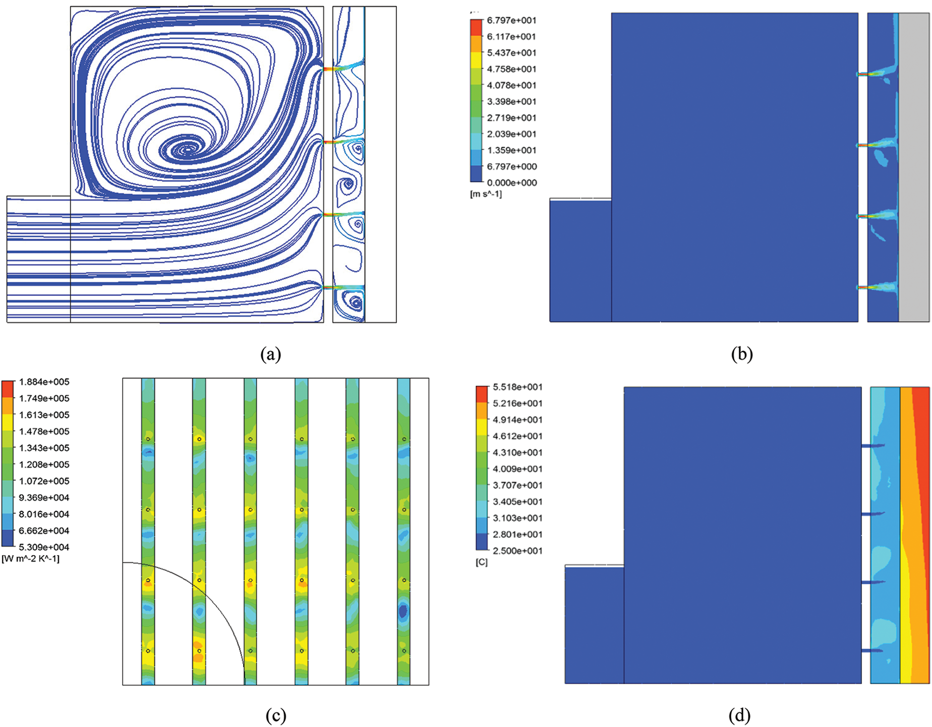
Figure 3: Simulated flow and temperature field according to Scheme 7. (a) Streamline in the device; (b) Velocity distribution in the center section of the device; (c) Local surface heat transfer coefficient contour of the cooling surface; (d) Temperature contour of the center section of the micro-channel
Figs. 4 and 5 illustrate the difference between a JIMC and a micro-channel heat sink, which share the same parameters provided in Scheme 16. The advantages of JIMC over micro-channel heat sink have been clearly demonstrated as follows.
(1) The jet impingement improves the local heat transfer coefficient and provides better temperature uniformity. For the microchannel device as shown in Fig. 4a, a temperature gradient is clearly displayed for the fluid in the channel from inlet to outlet. The heat transfer coefficient is also higher at the entrance of the micro-channel as shown in Fig. 4c. For the jet nozzles applied in JIMC device, as is shown in Fig. 4b, much better temperature uniformity is provided because of more evenly distributed working fluid by the micro jets. Notably, there are some hotspots around the jet region in Fig. 4b and the local SHTC also appear to lower near some nozzles in Fig. 4d. Those could be explained by the “drift phenomenon” [28] as shown in Fig. 3. For the jets at distance from the inlet, the effect of jet impingement to the coupling surface is weaken, resulting in lower local SHTC in their stagnation region.
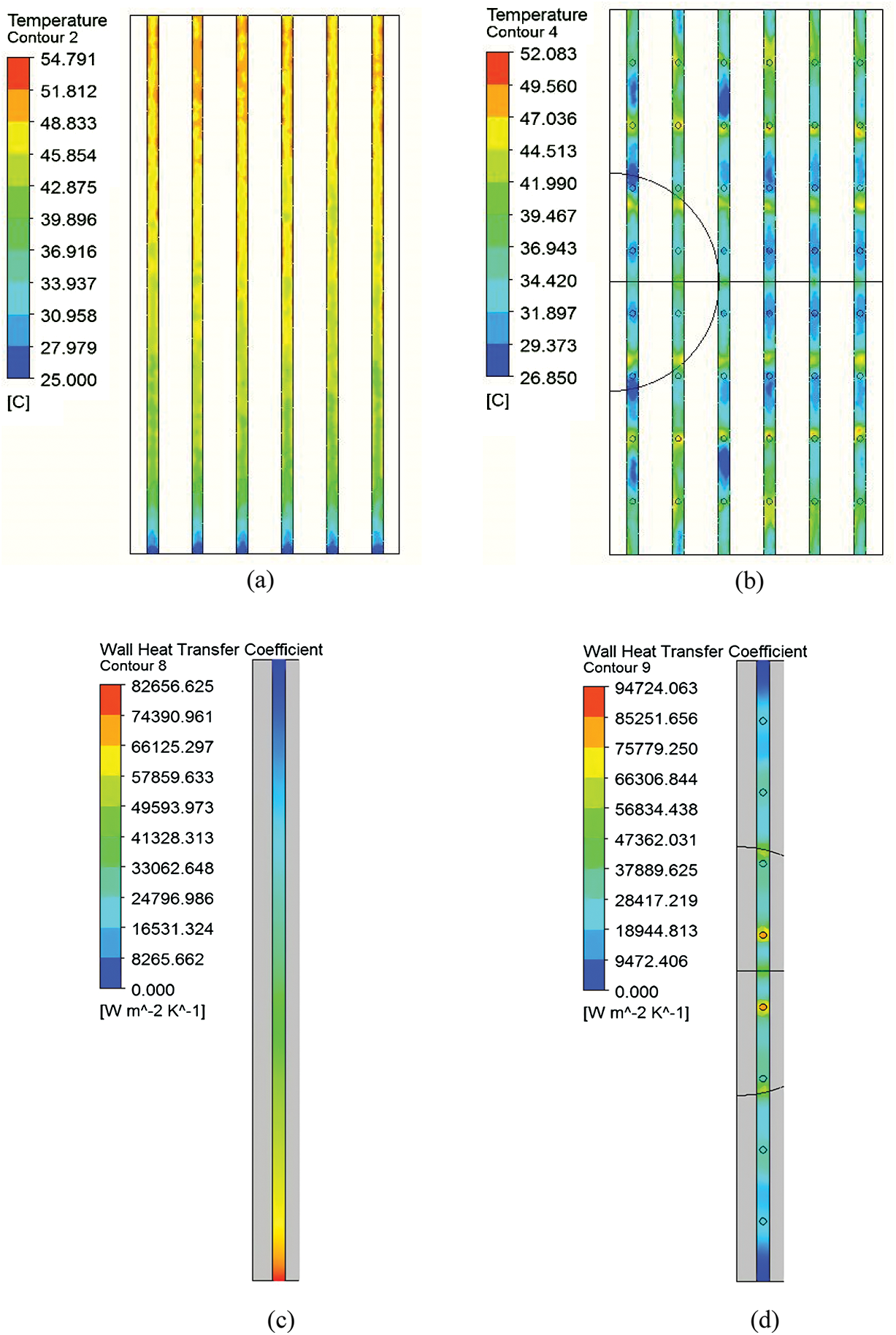
Figure 4: Temperature contour and heat transfer coefficient contour of the cooling surface. (a) Temperature contour of micro-channel cooling surface; (b) Temperature contour of JIMC cooling surface; (c) Cooling surface heat transfer coefficient of micro-channel model; (d) Cooling surface heat transfer coefficient of JIMC model
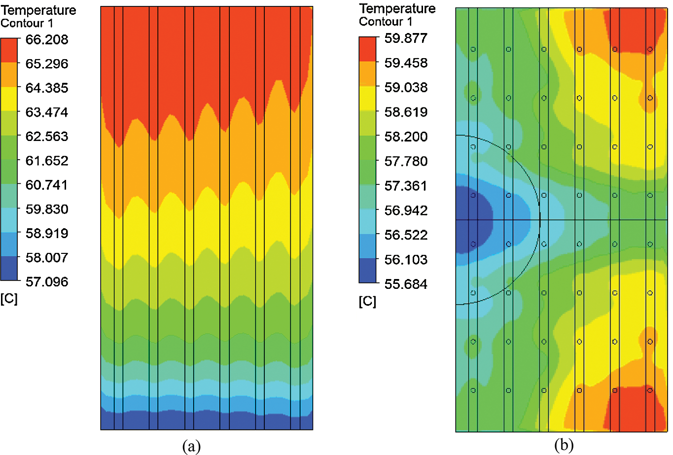
Figure 5: Temperature contour of the heat source. (a) Heat surface temperature of the micro-channel heat sink; (b) Heat surface temperature of the JIMC heat sink
(2) The JIMC heat sink performs better to reduce the hotspot temperature of the heat source. As it can be seen in Fig. 5a with respect the micro-channel heat sink, the temperature on the heat source displays a stepped distribution, and the hotspot temperature is 66.208°C. This is mainly because the water temperature gradually increases but SHTC decreases when it approaches to the outlet, thus the cooling effect decays. Nevertheless, in Fig. 5b, the multiple jets in JIMC provides cool water all along the channels, which lead to a smaller maximum temperature of the chip surface comparing to the micro-channel device. Consequently the temperature on the heat source surface of JIMC heat sink is symmetrically distributed, and the high temperature area is in two corners away from the inlet. The hotspot temperature on the heat source surface is only 59.877°C.
In this study, both temperature uniformity (evaluated by maximum temperature difference on heat source) and hotspot temperature (evaluated by maximum temperature on heat source surface) are considered as the main indices of heat sink performance. Corresponding to Tab. 1, the predicted performance of the presented design schemes is listed in Tab. 2.
As the hotspot temperature has more serious impact on the chip reliability, the optimal design solution was selected first according to the hotspot temperature in this study. As shown in Tab. 2, Scheme 7 tends to produce the lowest hotspot temperature and cause relatively small temperature difference, thus it is considered to be the optimal one of the 18 design schemes.
The range analysis method is very intuitive and widely used for data analysis of orthogonal tests results. In this study, the influence of different structural parameter groups on the cooling performance was also investigated by the range analysis method. Accordingly, the results of the same level of each factor were averaged separately. Each factor had three levels, so there are three mean values, by which its range value can be evaluated as follows:

where Rj is the range of the factor in the j column, and mji is the mean value of the three orthogonal test indicators of the j factor at the ith level.
Table 2: Predicted performance of the presented design schemes

Tab. 3 is the calculated maximum temperature difference range of the structural parameters and Tab. 4 is the maximum temperature range analysis. According to Tab. 3, the structural parameters which influence the maximum temperature difference of the heat source is sorted as follows: The relative width of the micro-channel (r1) > the relative height of the splitting chamber (r4) > the relative depth of the micro-channel (r2) > the number of micro-channels (N) > the ratio of jet hole length to diameter (r5) > the number of jet holes along the channel (k) > the relative diameter of the jet holes (r3).
Table 3: Calculated maximum temperature difference range of the structural parameters

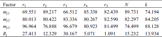
According to Tab. 4, the structural parameters which influences the hotspot temperature of the heat source is sorted as follows: The relative diameter of the jet holes (r3) > the relative width of the micro-channel (r1) > the number of micro-channels (N) > the number of jet holes along the channel (k) > the relative depth of the micro-channel (r2) > the relative height of the split chamber (r4) > the ratio of jet hole length to diameter (r5).
Table 4: Maximum temperature range analysis
It has been demonstrated that the relative diameter of the jet hole and the number of jet holes in each channel are inversely related to the heat dissipation performance, while the relative width of the micro-channel, the number of micro-channels, and the relative depth of the micro-channel are positively related to the heat dissipation performance. Since the chip’s highest temperature exerts a greater impact on thermal failure, the priority of parameter design should be for the better of making the maximum temperature as small as possible. In this manner, a set of optimized designs can be obtained according to the range analysis, that is: r1, r2, r3, r4, r5, N and k are equal to 0.25, 0.75, 0.25, 0.4, 3, 12, and 4, respectively. Correspondingly, a new model is established and tested. It is shown that the hotspot temperature of the chip surface is only 47.784°C while the temperature difference is 5.36°C. According to the principle that the highest temperature takes precedence over the temperature difference, the new parameters scheme is optimized.
In this study, an integrated model of the JIMC heat sink was established and validated, and then orthogonal tests were performed to investigate the influence of the structural parameter on the performance of the heat sink. It can be concluded that:
1. The presented numerical simulation method provides rational prediction of the coupling effects in the JIMC device. Based on this method, the flow field and temperature field in a JIMC device can be visually displayed.
2. JIMC demonstrates significant advantages over common micro-channel device in reducing the hotspot temperature and improving the thermal uniformity.
3. The orthogonal test presented in this study can systematically evaluate the effect of different parameters on the overall performance of the device, and produce the optimal design with relatively small computational cost.
4. The most important structural parameters which influences the hotspot temperature are the r3 (relative diameter of the jet hole), r1 (relative width of the micro-channel), and N (the number of micro-channels). And the most important structural parameters which influences the hotspot temperature of the heat source are r1 (relative width of the micro-channel), r4 the (relative height of the split chamber) and r2 (the relative depth of the micro-channel).
5. For the better design of a JIMC device, it is recommended to use smaller values of r1 (relative width of the micro-channel) and r3 (relative diameter of the jet hole) to reduce hotspot temperature, and to increase the height of the split chamber as possible for improving temperature uniformity.
Funding Statement: The research work was supported by National Natural Science Foundation of China (No. 51676030, Zhou, X. M., http://www.nsfc.gov.cn/) and Sichuan Science and Technology Program (No. 2019JDRC0026, Zhou, X. M., http://scst.tccxfw.com/).
Conflicts of Interest: The authors declare that they have no conflicts of interest to report regarding the present study.
1. Ebadian, M. A., Lin, C. X. (2011). A review of high heat flux heat removal technologies. Journal of Heat Transfer-Transactions of the ASME, 133(11), 122. DOI 10.1115/1.4004340. [Google Scholar] [CrossRef]
2. Sohel Murshed, S. M., Nieto de Castro, C. A. (2017). A critical review of traditional and emerging techniques and fluids for electronics cooling. Renewable and Sustainable Energy Reviews, 78, 821–833. DOI 10.1016/j.rser.2017.04.112. [Google Scholar] [CrossRef]
3. Yu, C. Y., Yu, X. Z. (2000). Preliminary study on electronic equipment thermal analysis/thermal design/thermal test technology. Microelectronics, 30(5), 334–337. [Google Scholar]
4. Mackowski, M. J. (1991). Requirements for high flux cooling of future avionics systems. Aerospace Technology Conference and Exposition, SAE, Pittsburgh, USA. [Google Scholar]
5. Ge, Z. J., Gu, Y. X., Wang, H. W. (2005). Finite element numerical simulation analysis of thermal loads on electronic packages. Journal of Dalian University of Technology, 45(5), 320–325. [Google Scholar]
6. Zhou, X. M., Shu, Z. Q., Liang, X. M., Jiang, C. J., Su, Y. C. et al. (2017). Investigation on the thermal performance of a novel micro-channel-aided device for vitrification of cells/tissues. Applied Thermal Engineering, 119(5), 189–196. DOI 10.1016/j.applthermaleng.2017.03.042. [Google Scholar] [CrossRef]
7. Zhou, X. M., Qiao, W. T., Zhang, X. L., Liu, Z., Gao, D. Y. (2015). Physical modeling of flow boiling in microchannels and its induced vitrification of biomaterials. International Journal of Heat and Mass Transfer, 83, 659–664. DOI 10.1016/j.ijheatmasstransfer.2014.12.063. [Google Scholar] [CrossRef]
8. Sung, M. K., Mudawar, I. (2008). Single-phase and two-phase heat transfer characteristics of low temperature hybrid micro-channel/micro-jet impingement cooling module. International Journal of Heat and Mass Transfer, 51(15–16), 3882–3895. DOI 10.1016/j.ijheatmasstransfer.2007.12.016. [Google Scholar] [CrossRef]
9. Asadi, M., Xie, G. N., Sunden, B. (2014). A review of heat transfer and pressure drop characteristics of single and two-phase microchannels. International Journal of Heat and Mass Transfer, 79, 34–53. DOI 10.1016/j.ijheatmasstransfer.2014.07.090. [Google Scholar] [CrossRef]
10. Naqiuddin, N. H., Saw, L. H., Yew, M. C., Yusof, F., Ng, T. C. et al. (2018). Overview of micro-channel design for high heat flux application. Renewable and Sustainable Energy Reviews, 82(1), 901–914. DOI 10.1016/j.rser.2017.09.110. [Google Scholar] [CrossRef]
11. Xie, S. Z., Beni, M. S., Cai, J. J., Zhao, J. Y. (2018). Review of critical-heat-flux enhancement methods. International Journal of Heat and Mass Transfer, 122, 275–289. DOI 10.1016/j.ijheatmasstransfer.2018.01.116. [Google Scholar] [CrossRef]
12. Sung, M. K., Mudawar, I. (2008). Single-phase hybrid micro-channel/micro-jet impingement cooling. International Journal of Heat and Mass Transfer, 51(17–18), 4342–4352. DOI 10.1016/j.ijheatmasstransfer.2008.02.023. [Google Scholar] [CrossRef]
13. Avadhesh, K. S., Santosh, K. S. (2019). The thermal and rewetting behavior of hot moving surface by water jet impingement. Applied Thermal Engineering, 159, 113950. DOI 10.1016/j.applthermaleng.2019.113950. [Google Scholar] [CrossRef]
14. Avadhesh, K. S., Lodhi, U. K., Kumar, G., Sahu, S. K. (2019). Effect of jet inclination and coolant flow rate on thermal and rewetting behavior during bottom jet impingement on hot horizontal surfaces. Steel Research International, 90(10), 1900171. DOI 10.1002/srin.201900171. [Google Scholar] [CrossRef]
15. M. Y. Liu, (2010). Numerical simulation of heat sink structure with high heat flux density combined with micro-channel and jet (Ph.D. Thesis). Tsinghua University, China. [Google Scholar]
16. Barrau, J., Omri, M., Chemisana, D., Rosell, J., Ibañez, M. et al. (2012). Numerical study of a hybrid jet impingement/micro-channel cooling scheme. Applied Thermal Engineering, 33–34, 237–245. DOI 10.1016/j.applthermaleng.2011.10.001. [Google Scholar] [CrossRef]
17. Zhang, Y. J., Wang, S. F., Ding, P. X. (2017). Effects of channel shape on the cooling performance of hybrid micro-channel and slot-jet module. International Journal of Heat and Mass Transfer, 113, 295–309. DOI 10.1016/j.ijheatmasstransfer.2017.05.092. [Google Scholar] [CrossRef]
18. Naphon, P., Nakharintr, L., Wiriyasart, S. (2018). Continuous nanofluids jet impingement heat transfer and flow in a micro-channel heat sink. International Journal of Heat and Mass Transfer, 126(A), 924–932. DOI 10.1016/j.ijheatmasstransfer.2018.05.101. [Google Scholar] [CrossRef]
19. Loganathan, R., Gedupudi, S. (2017). Numerical studies on single-phase micro-channel heat sink with multiple inlets along the channel. ICHMT Digital Library Online. http://www.dl.begellhouse.com/references/1bb331655c289a0a.html. [Google Scholar]
20. Yogesh, K. P. (2019). Influence of fin height on heat transfer and fluid flow characteristics of rectangular microchannel heat sink. International Journal of Heat and Mass Transfer, 137, 1041–1052. DOI 10.1016/j.ijheatmasstransfer.2019.04.012. [Google Scholar] [CrossRef]
21. Muszynski, T., Mikielewicz, D. (2017). Structural optimization of microjet array cooling system. Applied Thermal Engineering, 123, 103–110. DOI 10.1016/j.applthermaleng.2017.05.082. [Google Scholar] [CrossRef]
22. Kazachkov, I. V. (2019). On the modeling of non-classical problems involving liquid jets and films and related heat transfer processes. Fluid Dynamics & Materials Processing, 15(5), 491–507. DOI 10.32604/fdmp.2019.06477. [Google Scholar] [CrossRef]
23. Bentarzi, F., Mataoui, A. (2018). Turbulent flow produced by twin slot jets impinging a wall. Fluid Dynamics & Materials Processing, 14(2), 107–120. [Google Scholar]
24. Peng, M., Chen, L., Ji, W., Tao, W. (2020). Numerical study on flow and heat transfer in a multi-jet microchannel heat sink. International Journal of Heat and Mass Transfer, 157, 119–982. [Google Scholar]
25. Wilcox, D. C. (1998). Turbulence modeling for CFD. USA: DCW Industries. [Google Scholar]
26. Singh, D., Premachandran, B., Kohli, S. (2013). Numerical simulation of the jet impingement cooling of a circular cylinder. Numerical Heat Transfer, Part A: Applications, 64(2), 153–185. DOI 10.1080/10407782.2013.772869. [Google Scholar] [CrossRef]
27. Zhang, Y. X. (2019). Simulation and experimental research on heat sink heat dissipation performance combining jet and micro-channel (Ph.D. Thesis). Huazhong University of Science and Technology, China. [Google Scholar]
28. Huang, X., Yang, W., Ming, T., Shen, W., Yu, X. (2017). Heat transfer enhancement on a microchannel heat sink with impinging jets and dimples. International Journal of Heat and Mass Transfer, 112, 113–124. DOI 10.1016/j.ijheatmasstransfer.2017.04.078. [Google Scholar] [CrossRef]
 | This work is licensed under a Creative Commons Attribution 4.0 International License, which permits unrestricted use, distribution, and reproduction in any medium, provided the original work is properly cited. |