DOI: 10.32604/fdmp.2021.010051
ARTICLE
Study of the Combustion Process inside an Ethanol-Diesel Dual Direct Injection Engine Based on a Non-Uniform Injection Approach
1School of Mechanical Engineering, Guizhou Institute of Technology, Guiyang, 550003, China
2School of Mechanical Engineering, Guiyang University, Guiyang, 550005, China
*Corresponding Author: Yu Liang. Email: liangyumu@163.com
Received: 20 February 2019; Accepted: 21 December 2020
Abstract: The use of ethanol is a promising method to reduce the emissions of diesel engines. The present study has been based on the installation of a gasoline electronic injection system in a single-cylinder diesel engine to control the amount of ethanol entering the cylinder during the compression (while diesel has been injected into the cylinder by the original pump injection system). The injection time has been controlled by crank angle signal collected by an AVL angle indicator. In the tests ethanol and diesel each accounted for half of the fuel volume, and the total heat energy supply of the fuel was equivalent to that of the diesel under the operating conditions of the original engine. A three-dimensional combustion model of the diesel engine has been implemented by using the CFD software FIRE. Simulations have been carried out assuming uniform and non-uniform injections rate for the different holes and the different results have been compared. According to these results, a non-uniform injection rate can produce early ignition and cause an increase in the maximum in-cylinder pressure and the maximum average in-cylinder temperature. Moreover, in such conditions NO emissions are larger while soot emission is slightly lower.
Keywords: Combustion process; dual direct injection; diesel; ethanol; injection rate
The higher NOx and PM emissions of diesel engines are restricted by future stringent emission regulations [1]. As a renewable clean energy, the ethanol with the high latent heat of vaporization is regarded as the small-molecule oxygen-containing fuel. The use of ethanol is a promising method to reduce the NOx and PM emissions specified in diesel engines’ two regulations, which has aroused complete attention. However, the solubility between ethanol and diesel is very poor, limiting its application in diesel engines. Some researchers have proposed various forms of ethanol application in diesel engines, i.e., mixed combustion of small proportion ethanol and diesel [2–5], such as premixing or real-time mixing [6], ethanol inlet or nozzle injection, ignited by diesel [7], ethanol injection outside or inside the cylinder, and pressure combustion [8]. Ethanol direct injection into the cylinder exhibits the following advantages: the preparation process and avoiding additional cost making ethanol and diesel into stable mixed fuel. The amount of alcohol entering the cylinder is precisely controlled. Besides, the fuel deposition and emission of ethanol during valve overlapping and scavenging caused by poor atomization in the inlet can be avoided. Therefore, the diesel engine’s dynamic performance and thermal efficiency can be improved [9,10]. A study on the combustion process of ethanol-diesel engines was carried out [11]. The results show that, compared with diesel, the premixed combustion and diffusion combustion periods of ethanol-diesel fuel are shorter and more evident at high load, and the core of the heat release rate curve firstly deviates from TDC (top dead center) and then gets close to TDC along with the increase of diesel engine load. In [12], the ethanol injection test before diesel injection on the modified T1115 single-cylinder dual direct-injection diesel engine was carried out. It was found that the diesel engine cannot work stably when the ethanol injection was carried out 10°C a earlier than diesel injection. Therefore, to improve ethanol-diesel dual-fuel engines’ combustion stability, the numerical simulation study on the combustion process will be carried out in this paper to explore the mechanism of this type of combustion instability.
In this study, a gasoline electronic injection system is installed on a single-cylinder diesel engine to control ethanol’s amount entering the cylinder during the compression. At the same time, diesel is injected into the cylinder by the original pump injection system, forming a combustion mode in which ethanol and diesel are both directly injected into the cylinder, and ethanol is ignited by diesel compression ignition. According to the actual fuel injection rate and cyclic fuel injection quantity of each hole, the diesel engine’s three-dimensional combustion model is established using the software FIRE. The combustion simulations are carried out based on the implementation that uniform and non-uniform injection rates are performed for the different holes. Moreover, for the ethanol-diesel dual direct injection engine, the influence of the non-uniform injection rate from each hole on the combustion process is compared and analyzed to establish the foundation which can accurately describe the combustion process of the diesel engine fueled with ethanol [13].
In this paper, the test equipment and methods are summarized in Section 2. The combustion model is discussed in Section 3. Presented in Section 4 are combustion simulation results and analysis. Finally, the conclusions are addressed in Section 5.
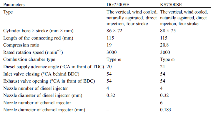
Two diesel generators are transformed and used for the test. The first transformation is based on the DG7500SE diesel generator, and the second is based on the KS7500SE diesel generator. The main technical parameters of the two engines are shown in Tab. 1, respectively.
Table 1: Summary of engine specifications
On the first diesel generator (DG7500SE), an ethanol-diesel mixture test experiment is conducted, and the results are used to verify the developed 3D combustion model. Details are presented in reference [14].
The ethanol-diesel direct injection test is carried out on the second diesel generator (KS7500SE). A diagrammatic representation of the test bench is shown in Fig. 1. The diesel fuel (0# diesel) is purchased from a gas station (PetroChina), and the content of ethanol is no less than content 99.5%. The physical and chemical properties of the fuel are shown in Tab. 2. The generator is first started with diesel and preheated for 5 min under no-load. After it operates subsequently for 10 min, 10 min, and 5 min under 1.5 kW, 3.0 kW, and 4.5 kW loads, ethanol is injected, and the replacement rate of ethanol is gradually increased. As the electronic engine governor operates under the condition that the engine continually runs at 3000 rpm, diesel injection quantity is gradually reduced. The fuel consumption per minute is determined during the test. Since when the diesel consumption is 29–33 mL per minute, ethanol consumption is about 28–34 mL per minute, and therefore this makes the rate of consumption of diesel and ethanol almost 1:1. The tested power referred to the power consumed by the electric load is lower than the engine’s actual power. During the test, the fuel consumption and emission data are measured, and the cylinder pressure of 100 cycles are continuously collected.
Table 2: Physical and chemical properties of a fuel
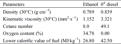
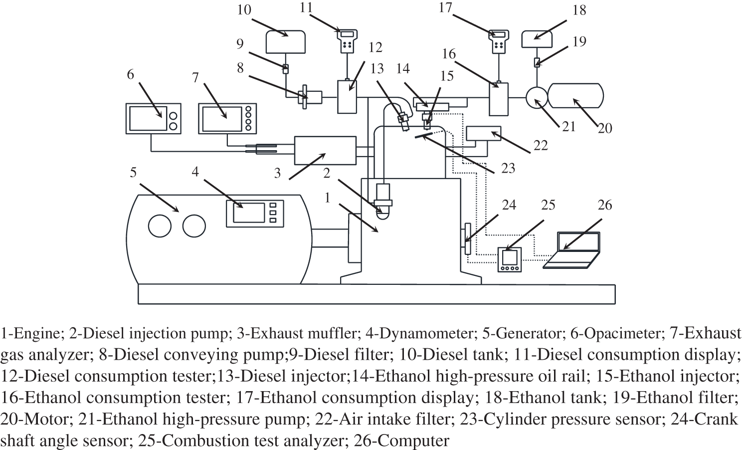
Figure 1: Schematic diagram of the test bench
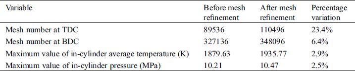
The geometric model of the combustion chamber at TDC is drawn by the software ProE. The mesh is divided by Hypermesh, and the meshed model is imported into software AVL FIRE to set up the dynamic mesh for calculation and post-processing analysis. The diesel injector has four uniformly distributed holes, while the ethanol injector has six non-uniform distributed holes. The angles between each hole’s injection direction of the two injectors and the cylinder’s cross-section are not the same. The injection position and oil spray distribution are shown in Fig. 2. In order to describe the spray cloud image in the post-processing of simulation results, two sections are defined, i.e., Section A is the section through the center of the diesel injector, and Section B is the section through the center of the ethanol injector, as shown in the figure. Both of them are symmetrical surfaces of the injected oil beams. The area close to the nozzle hole, and the boundary is densely meshed [15,16]. The number of mesh cells at TDC is 110,496, and that at BDC (bottom dead center) is 348,096. The simulation accuracy is improved by 2–3% after mesh refinement, as shown in Tab. 3. The meshed combustion chamber at TDC is shown in Fig. 3. The chemical reaction kinetics is achieved using the standard ethanol and diesel transportation sub-model in AVL FIRE [17,18]. The main sub-models selected for the computation are shown in Tab. 4.
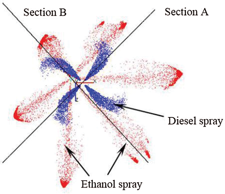
Figure 2: Diesel and ethanol injection position and fuel spray
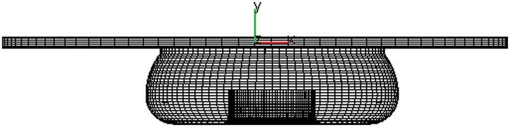
Figure 3: Combustion chamber mesh at top dead center
Table 3: Mesh sensitivity analysis

In the combustion model, the governing equation of momentum conservation is expressed as:

where  is the fluid density,
  is time,
  is the free index,
  is substantial derivative,
  is velocity vector,
  is gravitational acceleration,
  is the change of crystal nucleus,
  is unit stress.
The governing equation of energy conservation is expressed as:

where  is enthalpy,
  is heat flux,
  is pressure,
  is shear stress,
  is the coefficient of thermal conductivity,
  is the temperature.
The governing equation of mass conservation is expressed as:

where  is the component concentration,
  is local diffusion term per unit time
  at the control boundary.
The turbulent flow is simulated by the Renormalization Group Theory (RNG)  formula [19]. Turbulent energy transport equation is expressed as:

where  is density,
  is turbulent flow energy,
  is mean stress product,
  is gravity product,
  is turbulent kinetic energy dissipation rate,
  is dynamic viscosity,
  is equivalent viscosity coefficient.
Turbulent energy dissipation equation can be expressed as:

where  ,
,  ,
,  and
and  , which are turbulence model constants.
The diesel injection starting point is 344°CA, and the ethanol injection starting point is 240°CA. The diesel injection rate is measured on an established measurement system for the transient injection rate of each nozzle hole [20], as shown in Fig. 4. The combustion simulations are carried out. Each hole’s uniform injection rate and the measured non-uniform injection rate of each hole are established, respectively, as the diesel injection setting. The ethanol injection setting is adopted as the consistent fuel injection rate of each hole since ethanol’s control is more accurate by using the gasoline engine direct injection system. The difference in the injection rate between nozzle holes is small because of the low viscosity of ethanol. Due to ethanol injection’s first order, the evaporation and atomization time is longer, and the premixing is sufficient. Thus, the injection difference between nozzle holes on ethanol’s distribution in the cylinder is minor.
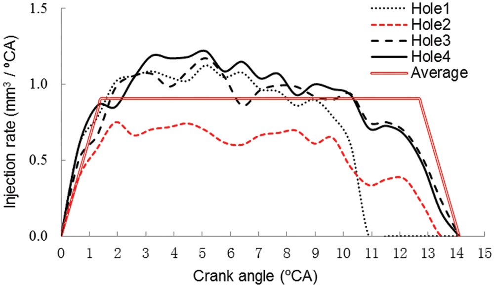
Figure 4: Injection rate of each hole
The temperatures of the bottom of the cylinder head, the cylinder wall, and the piston pits are set as 553 K, 523 K, and 593 K, respectively. The initial temperature is set as 393 K, and the initial pressure is set as 1.18 bar at intake valve closure. The simulation settings for the injector positions and directions and the nozzle holes are presented in Tab. 5.
Table 5: Setting of injectors and nozzle holes

The profile curve of simulated and experimental values of cylinder pressure at corresponding crank angles during combustion and at maximum combustion pressure are closely related throughout the process (shown in Fig. 5). It is worth noting that the curve for the case of the measured injection rate is closer to the measured value of cylinder pressure than the curve for the case of the assumed uniform injection rate.
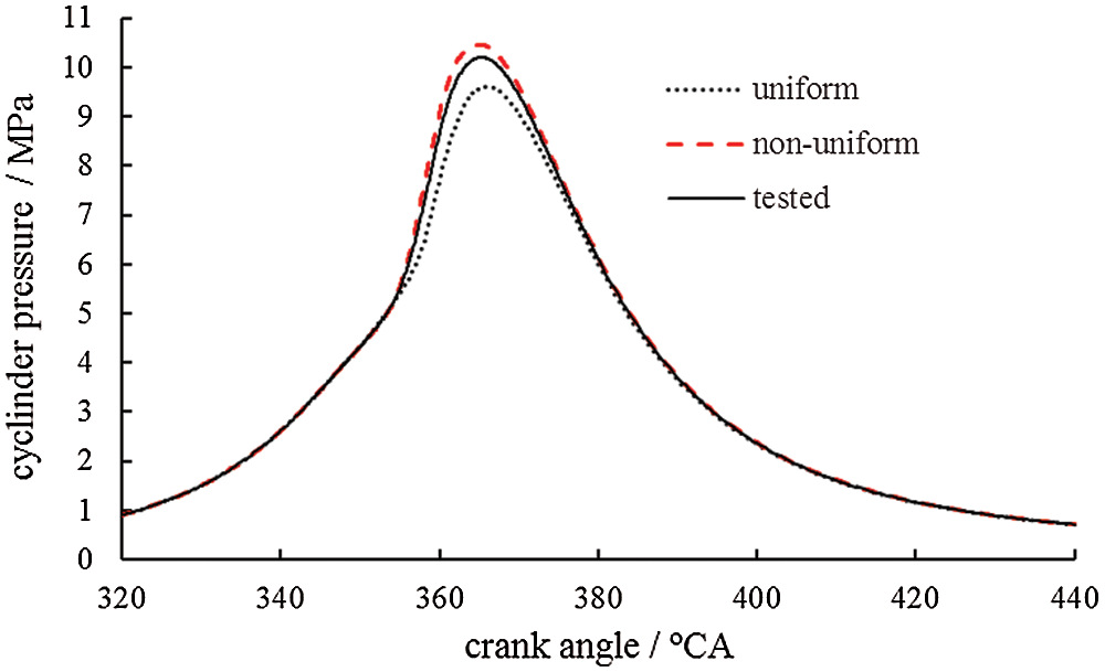
Figure 5: Measured and simulated validation cylinder pressures at standard conditions
4 Combustion Simulation Results and Analysis
For the convenience of description in this paper, the simulated condition based on the uniform injection rate of each hole is referred to as “Uniform Condition,” and the simulated condition based on the measured non-uniform injection rate of each hole is referred to as “Non-uniform Condition.”

Figure 6: Spray cloud of each hole (a) 350°CA (b) 360°CA
From Fig. 6, it can be seen that the fuel spray driven by the circulating gas in the cylinder is deflected along the circulation direction. The fuel injection has lasted for 6°CA at 350°CA. During the early injection period, some holes have longer penetration distance due to non-uniform fuel injection. This makes the distribution of corresponding fuel mist more comprehensive, and the interaction between fuel mist and air more sufficient. As a result, the explosive mixture’s formation is promoted by the faster breaking, evaporation, and atomization. The fuel particles of the fuel beam injected in the early stage mix with air, which forms the fuel-air mixture more quickly.
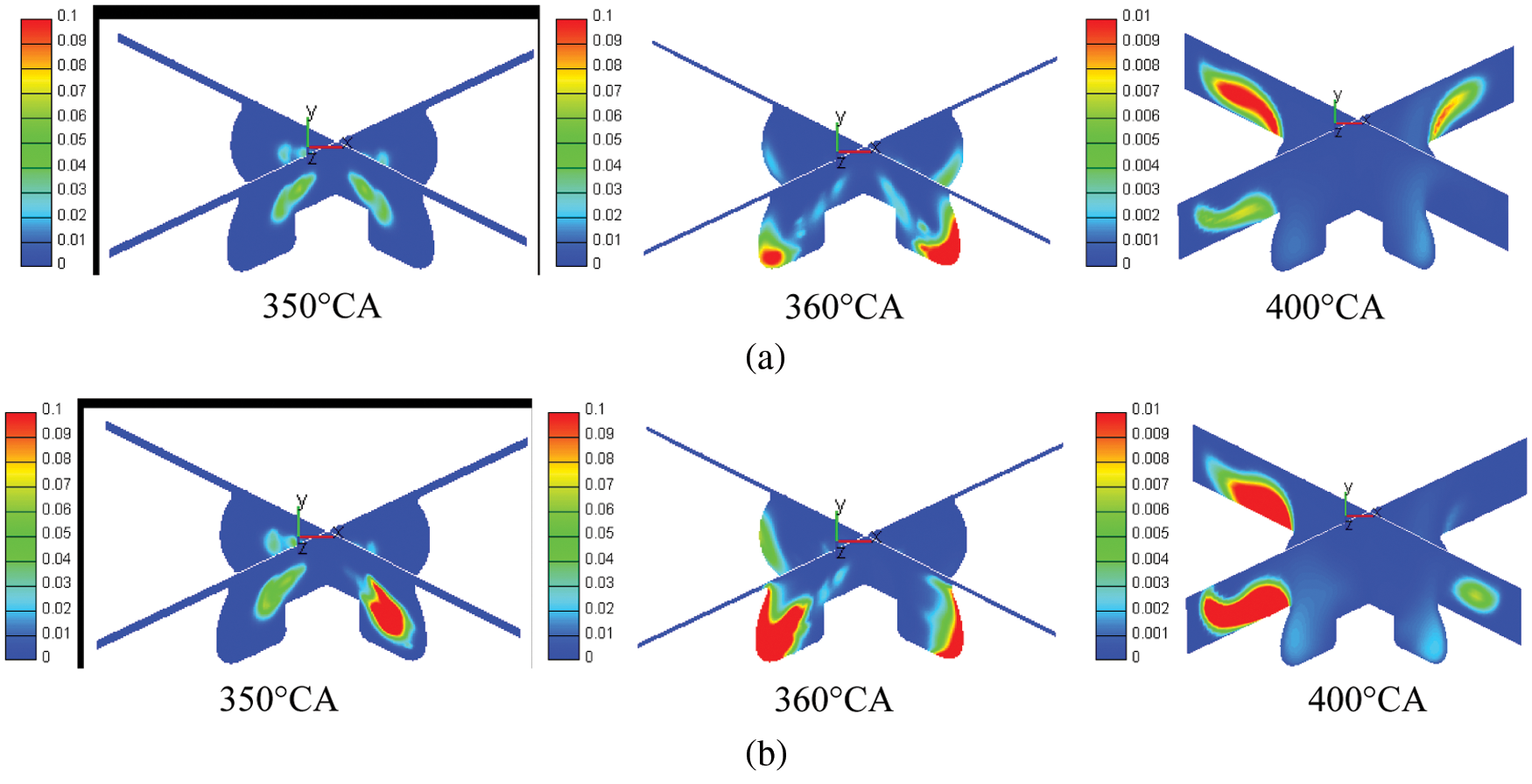
Figure 7: Mass concentration distribution of diesel components (a) Uniform condition; (b) Non-uniform condition

Figure 8: Temperature distribution (a) Uniform condition; (b) Non-uniform condition
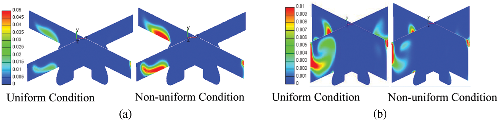
Figure 9: Mass concentration distribution of ethanol components (a) 400°CA; (b) 440°CA
As shown in Fig. 7, there is already a relatively high concentration of fuel components at 350°CA for non-uniform injection from four holes of diesel injector. Fig. 8 shows that in the periphery of the fuel beam with a high injection rate in the early stage, a more comprehensive range of high-temperature region appears at 355°CA due to the faster evaporation atomization of the fuel in an individual beam, indicating that ignition has occurred. Moreover, a relatively small range of high-temperature regions appears at 355°CA, and the explosive mixture begins to catch fire for the uniform injection rate of each hole. It can be seen that in the case of the non-uniform injection rate of each hole, the injection rate of the individual hole is large, which shortens the ignition delay period and advances the combustion starting point. At the beginning of combustion, the piston moves upward to TDC. Therefore, the temperature and pressure in the cylinder rise rapidly, and airflow disturbance is strengthened. This leads to accelerated evaporation, atomization, mixing, and ignition conditions. As a result, the combustion proceeds more rapidly [6].
The high temperature and pressure in the cylinder accelerate the atomization of the fuel particles. Fig. 6 shows that most of the fuel particles injected in the early stage have been vaporized and atomized under the condition of a non-uniform injection rate at 360°CA. As a result, a large amount of fuel is added to the combustion. The temperature and pressure in the cylinder are significantly higher than those under a uniform injection rate. In the non-uniform injection rate, the fuel components’ concentration is higher in the area near the combustion chamber wall. The range of high-temperature region is more comprehensive. This higher and broader temperature distribution in the cylinder will result in a more considerable amount of NO production [21].
From Figs. 7 and 9, the concentration of fuel components is higher in the upper end of the piston and near the wall at 400°CA in the case of non-uniform injection rate. It can be explained by that the injection rate of the individual nozzle hole is high, and the fuel injection amount is large under the condition of a non-uniform injection rate. Thus, the fuel hitting the wall and attached to the wall surface is increased. Simultaneously, the corresponding area’s air-fuel ratio is relatively low, and the diffusion combustion is incomplete. If the fuel components of this part cannot be fully and sufficiently burned at the later combustion stage, HC and CO emission will be higher than that in the case of a uniform injection rate. However, Fig. 9(b) shows that the ethanol component in the case of the non-uniform injection rate is slightly lower than that in the case of a uniform injection rate at 440°CA. This indicates that there is still excess air at the later stage of combustion to ensure fuel combustion under the non-uniform injection rate condition. At this time, the heat released by combustion reduces the temperature drop rate, which is beneficial to the diffusion combustion of fuel components near the wall [22].
Figs. 10 and 11 present the in-cylinder average temperature and accumulated heat release and the in-cylinder pressure and heat release rate, respectively. Soot and NO mass fraction in the cylinder are presented in Fig. 12.
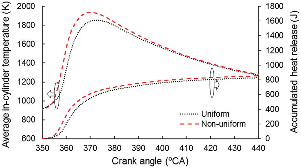
Figure 10: Average in-cylinder temperature and accumulated heat release
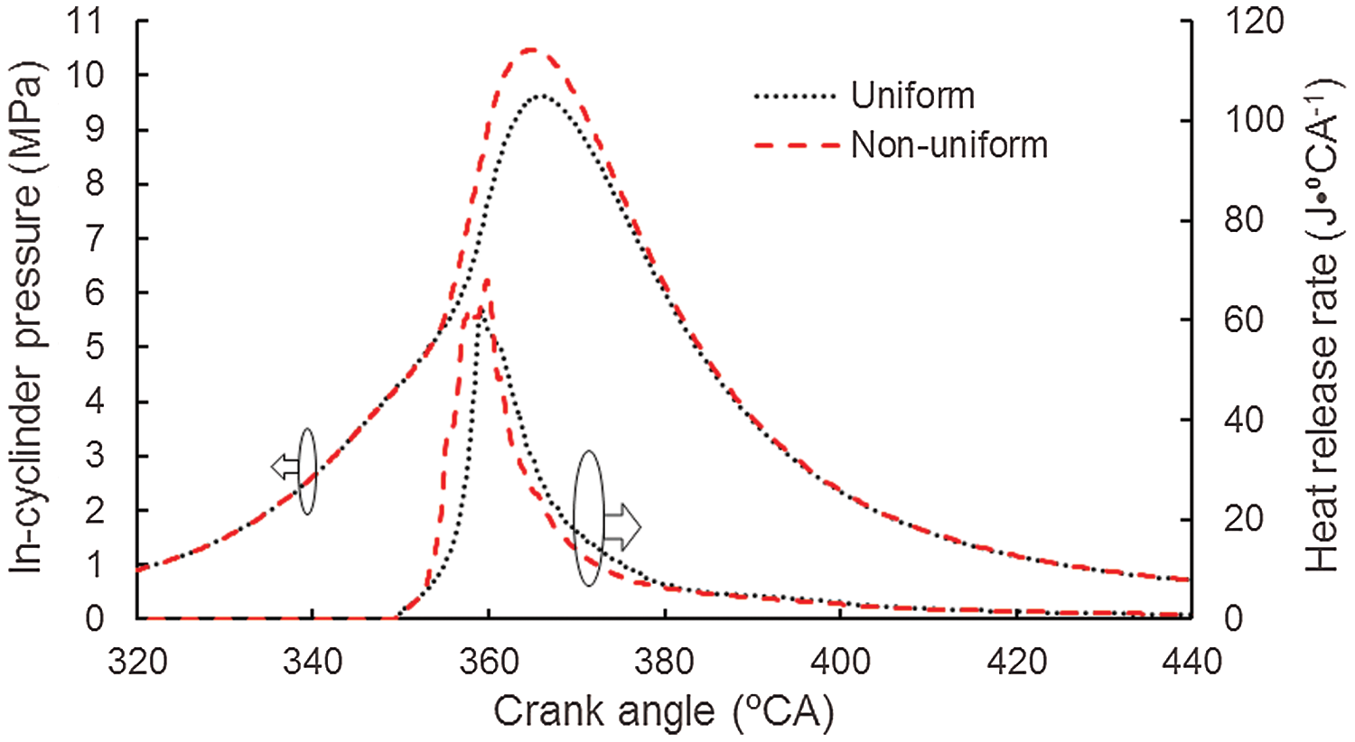
Figure 11: In-cylinder pressure and heat release rate
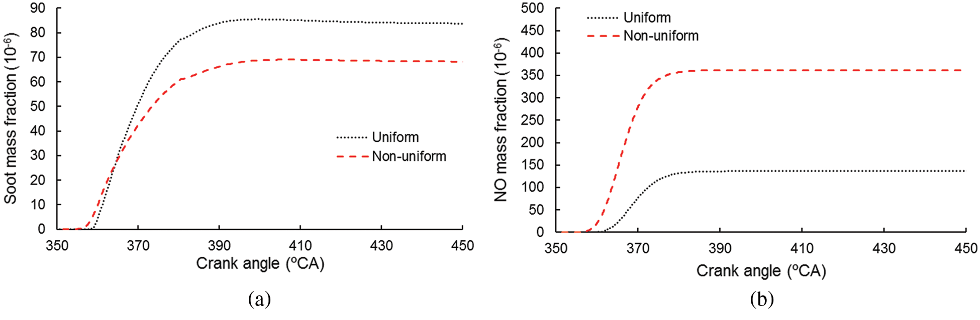
Figure 12: Soot and NO mass fraction in the cylinder (a) Soot mass fraction (b) NO mass fraction
According to Figs. 10–12, and the previous analysis, it can be found that compared with the uniform injection rate, the ignition under the condition of the non-uniform injection rate is slightly advanced. The combustible mixture formed during the ignition delay period and the heat release rate during the early combustion period are increased. At this time, the piston is near the top dead center, which makes the in-cylinder pressure rise faster, and the maximum in-cylinder pressure increase. From the perspective of the combustion heat release rate curve, the heat release is earlier, and the combustion process proceeds slightly earlier in the case of non-uniform injection rate. The combustion heat release rate during the later combustion period is the same in the two investigated cases. When the injection rate from four holes is uneven, the in-cylinder temperature during the early period and the maximum in-cylinder pressure are higher. From the accumulated heat release rate, compared with those under the condition of the uniform injection rate, the heat releases in the early, and later combustion stages are relatively larger under the condition of the non-uniform injection rate. Thus, the thermal efficiency of the non-uniform injection rate is slightly higher. Besides, the non-uniform injection rate’s in-cylinder temperature is no lower than that of the uniform injection rate in the later combustion stage. The NO production is higher while the soot production is lower in the case of non-uniform injection rate.
When each hole’s injection rate is non-uniform, some holes exhibit a large injection rate and injection quantity, while the others exhibit low injection rates and injection quantity. The holes with a high injection rate have a considerable spray penetration distance, and the fuel distribution in the space is wider at the same time. Thus, the injected fuel can mix with more air, which forms more premixed gas in a shorter time than the holes with a low injection rate. Too much fuel injection increases the fuel impinging on the wall and attached to the wall. Simultaneously, the air-fuel ratio in this area is relatively low, so the diffusion combustion is incomplete. The evaporation, atomization, and mixing of fuel spray are slightly slower for the holes with a low injection rate. However, the air in the area where the fuel spray is located is relatively sufficient, beneficial to the entirely sufficient combustion. Under the comprehensive effect of these factors, the following conclusions can be drawn on the foundation of engine parameters’ characteristics and the non-uniform injection rate.
(1) When the injection rate from four holes of diesel injector is non-uniform, the individual nozzle hole with a higher transient injection rate exhibits more considerable spray penetration distance. The fuel-air mixing is relatively sufficient, which makes the ignition starting point earlier.
(2) The phase corresponding to the heat release rate curve is earlier under the non-uniform injection rate condition. Simultaneously, the initial combustion is in the late stage of the compression stroke, making the maximum in-cylinder pressure and temperature rise quickly. Therefore, compared with the condition of uniform injection rate, the maximum in-cylinder pressure, the maximum in-cylinder average temperature, and NO production is higher, the production of soot is slightly lower, and the accumulated heat release is slightly larger.
Funding Statement: The author(s) disclosed receipt of the following financial support for the research, authorship, and publication of this article: this research is funded by the National Natural Science Foundation of China (Nos. 51476072 and 51366002), the Science and Technology Foundation of Guizhou Province (No. [2018] 1006), Supporting Program for Top Scientific and Technological Talents in Universities of Guizhou Province (No. [2018] 062), High-level Talent Research Funding Project of Guizhou Institute of Technology and Key Construction Projects of the First Class University (Phase I) of Guizhou Province in 2017-the First Class Course (Nos. 2017158418 and 2017158435).
Conflicts of Interest: The authors declare that they have no conflicts of interest to report regarding the present study.
1. Liang, J. J., Song, Z., Zhang, P. L. (2019). An experimental study on fuel combustion under external irradiance. Fluid Dynamics & Materials Processing, 15(4), 455–458. [Google Scholar]
2. Shan, Y., Ye, L. H., Sun, C. W., Meng, W. X. (2018). Experimental study on the emission of F-T diesel blended with ethanol/n-butanol. Renewable Energy Resources, 36(5), 650–655. [Google Scholar]
3. Cao, Z. K., Xu, B., Liu, F. J., Hu, Y. K., Wang, Z. C. et al. (2019). Effect of engine exhaust temperature on ethanol oxidation to formaldehyde. Renewable Energy Resources, 37(4), 507–512. [Google Scholar]
4. Gnanamoorthi, V., Devaradjane, G. (2015). Effect of compression ratio on the performance, combustion, and emission of DI diesel engine fueled with the ethanol-diesel blend. Journal of the Energy Institute, 88(1), 19–26. DOI 10.1016/j.joei.2014.06.001. [Google Scholar] [CrossRef]
5. Li, M. D., Wang, Z., Xu, G. J., Chen, L., Li, L. L. (2012). Experimental investigation on combustion and emission characteristics of a diesel engine fueled with ethanol/diesel blends. Transaction of the Chinese Society Agricultural Engineering, 28(2), 29–34. [Google Scholar]
6. Murcak, A., Hasimoglu, C., Cevik, I., Karabektas, M., Ergen, G. (2013). Effects of ethanol–diesel blends to the performance of a DI diesel engine for different injection timings. Fuel, 109(2), 582–587. DOI 10.1016/j.fuel.2013.03.014. [Google Scholar] [CrossRef]
7. Datta, A., Mandal, B. K. (2016). Impact of alcohol addition to diesel on the performance combustion and emissions of a compression ignition engine. Applied Thermal Engineering, 98(1), 670–682. DOI 10.1016/j.applthermaleng.2015.12.047. [Google Scholar] [CrossRef]
8. Ma, Y. P., Liu, F. S., He, X., Li, X. R. et al. (2014). Visualization of combustion characteristics of intake port-injected ethanol ignited by diesel fuel. Transactions of CSICE, 32(4), 296–301. [Google Scholar]
9. Botero, M. L., Huang, Y., Zhu, D. L., Molina, A., Law, C. K. (2012). Synergistic combustion of droplets of ethanol, diesel and biodiesel mixtures. Fuel, 94, 342–347. DOI 10.1016/j.fuel.2011.10.049. [Google Scholar] [CrossRef]
10. Natarajan, S., Kumar, M. A., Sundareswaran, A. U. M. (2017). Computational analysis of an early direct-injected HCCI engine using bioethanol and diesel blends as fuel. Energy Procedia, 105, 350–357. DOI 10.1016/j.egypro.2017.03.325. [Google Scholar] [CrossRef]
11. Hu, P., Wu, C. L., Wang, W. (2016). The combustion process of a diesel engine fueled with ethanol-diesel blends. Chinese Journal of Automotive Engineering, (2), 131–136. [Google Scholar]
12. Fang, X. Z., Liu, X. J., Li, G. L., Xu, C. (2005). Development of a compression ignition test engine with dual direct injection systems. Journal of Jilin University (Engineering and Technology Edition), 35(1), 34–38. [Google Scholar]
13. Wang, C., Wang, X. C., Wu, Y. Y., Liu, H. F., Jin, C. et al. (2020). Effects of ethanol/PODE/diesel blends and injection strategies on a diesel engine’s combustion and emissions. Acta Scientiae Circumstantial, 40(3), 854–864. [Google Scholar]
14. Liang, Y., Zhang, T., Zhong, L. Q., Xu, M. F., Peng, J. et al. (2015). Exhaust gas recirculation improving economic and emission properties of cylinder diesel generator fueled with biodiesel. Transactions of the Chinese Society of Agricultural Engineering, 31(24), 23–29. [Google Scholar]
15. Li, X. R., Chen, Y. L., Zhao, L. M., Liu, F. S. (2017). Calibration method on improving simulating accuracy of the combustion process in diesel engines. Transactions of the Chinese Society of Agricultural Engineering, 33(4), 102–110. [Google Scholar]
16. Zhou, B. (2011). Simulation study on the combustion process of the DI diesel engine. Design & Manufacture of Diesel Engine, 17(4), 6–11. [Google Scholar]
17. Jiao, Y. J., Zhang, H. M., Li, F. C. (2008). Multi-dimensional simulation and analysis of the combustion process in DI diesel. Tractor & Farm Transporter, 35(3), 49–52. [Google Scholar]
18. Wu, J., Xu, B., Ma, Z. h., Bao, X. F., Sun, X. W. (2010). Simulation & analysis of the combustion process in diesel based on AVL FIRE. Small Internal Combustion Engine and Motorcycle, 39(3), 5–8. [Google Scholar]
19. Dai, J. C., Mou, J. G., Liu, T. (2020). Influence of tip clearance on unsteady flow in the automobile engine pump. Fluid Dynamics & Materials Processing, 16(2), 161–179. DOI 10.32604/fdmp.2020.06613. [Google Scholar] [CrossRef]
20. Zhou, L. Y., Dong, S. F., Cui, H. F., Wu, X. W., Xue, F. Y. et al. (2016). Measurements and analyses on the transient discharge coefficient of each nozzle hole of multi-hole diesel injector. Sensors and Actuators A: Physical, 244(3), 198–205. DOI 10.1016/j.sna.2016.04.017. [Google Scholar] [CrossRef]
21. Liang, Y., Zhou, L. Y., Yao, G. W., Xu, M. F., Yuan, B. et al. (2018). Simulation analysis of load characteristics of a small diesel generator fueled with the ethanol-diesel blend. Renewable Energy Resources, 36(7), 963–968. [Google Scholar]
22. Park, S., Kim, H. J., Shin, D. H., Lee, J. (2018). Effects of various split injection strategies on combustion and emissions characteristics in a single-cylinder diesel engine. Applied Thermal Engineering, 140(1), 422–431. DOI 10.1016/j.applthermaleng.2018.05.025. [Google Scholar] [CrossRef]
 | This work is licensed under a Creative Commons Attribution 4.0 International License, which permits unrestricted use, distribution, and reproduction in any medium, provided the original work is properly cited. |