
 Submit a Paper
 Propose a Special lssue
 Open Access
ARTICLE

Study on Optimization of Two-Stage Phase Change Heat Storage Coupled Solar-Air Source Heat Pump Heating System in Severe Cold Region
1 School of Civil and Architectural Engineering, Cangzhou Jiaotong College, Huanghua, 061199, China
2 School of Mechanical and Power Engineering, Cangzhou Jiaotong College, Huanghua, 061199, China
3 China Resources Electric Power (Bohai New Area) Co., Ltd., Huanghua, 061199, China
* Corresponding Author: Yan Jia. Email:
(This article belongs to the Special Issue: Future Innovative Solar Collectors, Technologies, and Materials for Sustainable Development)
Energy Engineering 2025, 122(4), 1603-1627. https://doi.org/10.32604/ee.2025.062908
Received 30 December 2024; Accepted 24 February 2025; Issue published 31 March 2025
 View Full Text
 Download PDF
Abstract
The development of efficient and clean heating technologies is crucial for reducing carbon emissions in regions with severe cold regions. This research designs a novel two-stage phase change heat storage coupled solar-air source heat pump heating system structure that is specifically designed for such regions. The two-stage heat storage device in this heating system expands the storage temperature range of solar heat. The utilization of the two-stage heat storage device not only makes up for the instability of the solar heating system, but can also directly meet the building heating temperature, and can reduce the influence of low-temperature outdoor environments in severe cold regions on the heating performance of the air source heat pump by using solar energy. Therefore, the two-stage phase change heat storage coupled to the solar energy-air source heat pump heating system effectively improves the utilization rate of solar energy. A numerical model of the system components and their integration was developed using TRNSYS software in this study, and various performance aspects of the system were simulated and analyzed. The simulation results demonstrated that the two-stage heat storage device can effectively store solar energy, enabling its hierarchical utilization. The low-temperature solar energy stored by the two-stage phase change heat storage device enhances the coefficient of performance of the air source heat pump by 11.1% in severe cold conditions. Using the Hooke-Jeeves optimization method, the annual cost and carbon emissions are taken as optimization objectives, with the optimized solar heat supply accounting for 52.5%. This study offers valuable insights into operational strategies and site selection for engineering applications, providing a solid theoretical foundation for the widespread implementation of this system in severe cold regions.Graphic Abstract
Keywords
Energy is a cornerstone of the contemporary global economy, yet the escalating dependence on non-renewable energy sources, particularly fossil fuels, is fueling a deepening global energy crisis [1,2]. This reliance is accompanied by profound environmental repercussions, including severe pollution and an intensification of the greenhouse effect, which accelerates soil erosion and desertification [3]. Consequently, the optimization and modernization of energy infrastructure have emerged as critical priorities for nations across the globe. The transformation of global energy infrastructure from traditional fossil fuel dependence to renewable energy sources represents a crucial evolutionary process in energy system restructuring. However, the implementation of an immediate and comprehensive transition from fossil-based energy systems remains impractical within the current temporal framework. Empirical data from 2021 reveals a significant escalation in worldwide primary energy consumption, which experienced a notable 5.8% growth compared to 2020 levels. Furthermore, when analyzed against pre-pandemic figures, this consumption demonstrated a 1.3% increase relative to 2019 metrics. This substantial growth in energy demand underscores the complex challenges associated with rapid energy transition strategies. This growth effectively reversed the decline in energy demand observed in 2020. The unprecedented escalation in global energy demand has precipitated a corresponding surge in greenhouse gas emissions, particularly carbon dioxide. Recent data indicates that worldwide carbon emissions experienced a substantial 5.7% increase in 2021, culminating in the release of 39 gigatons of carbon dioxide (CO2) into the atmosphere. More specifically, energy-related emissions accounted for 33.9 gigatons of this total, marking a 5.9% rise compared to 2020 and approaching pre-pandemic emission levels recorded in 2019 [4]. While the international community continues to demonstrate growing commitment to the adoption of environmentally friendly energy alternatives, fossil fuel consumption persists at elevated levels. The contemporary energy paradigm is experiencing a fundamental restructuring, manifested through two parallel developments: the accelerating integration of renewable energy infrastructure and the heightened prioritization of sustainable development practices [5]. In response to these global challenges, an increasing number of countries are implementing advanced clean energy solutions as part of their strategic initiatives to reduce fossil fuel dependency and curb atmospheric carbon concentrations [6–8].
Building related CO2 emissions encompass the greenhouse gases emitted during the entire life cycle of a building, spanning the production of construction materials, the construction process, operational activities, and eventual demolition [9]. Each phase of a building’s life cycle exhibits distinct characteristics related to CO2 emissions. During the production of building materials, significant amounts of carbon dioxide are generated, particularly in the manufacturing of energy intensive materials such as cement and steel [10]. In the construction stage, CO2 emissions arise from the operation of machinery and the transportation of building materials. In the operational phase, daily energy consumption, including heating, cooling, and lighting, constitutes the primary source of CO2 emissions [11]. During the demolition phase, waste disposal and the transportation of debris also contribute to CO2 emissions [9]. In all these stages, operational emissions account for over 70% of the total CO2 emissions throughout a building’s life cycle [12]. In particular, the heating is a major contributor to CO2 emissions during the operational phase. The heating energy consumption can exceed 50% of a building’s total energy use in severe regions [13]. The intensity of CO2 emissions is influenced by numerous factors. Firstly, in severe cold regions, extended heating periods and high energy demands result in significantly higher CO2 emissions compared to warmer areas. Secondly, buildings with inadequate thermal insulation require more energy to maintain indoor comfort, while outdated boilers and inefficient pipe networks often lead to substantial heat losses. Lastly, heating systems reliant on coal produce far greater CO2 emissions than those powered by natural gas or other renewable energy sources. Consequently, achieving a low carbon transformation in the heating sector remains a formidable challenge, necessitating innovative solutions and systemic upgrades to reduce emissions more effectively.
Energy consumption in buildings represents a significant portion of global energy use, underscoring the importance of adopting renewable energy solutions as a strategic pathway to advancing building energy conservation. The promotion of renewable energy sources, such as solar energy [14], bioenergy [15], and geothermal energy [16], for heating purposes not only provides a sustainable alternative to conventional energy systems but also enhances the quality of life and comfort for residents in both urban and rural settings. This shift significantly reduces dependence on traditional primary energy sources. Among these renewable options, solar energy emerges as a particularly promising solution for building heating, offering benefits such as low operational costs and substantial environmental and economic advantages. China, with its vast and abundant solar resources, is uniquely positioned to leverage solar energy effectively. Approximately two-thirds of the country enjoys more than 2200 h of annual sunshine, with solar radiation levels exceeding 5000 MJ/m2 per year [17]. Solar thermal collectors, which are designed to harness incident solar radiation and subsequently transfer thermal energy to a working fluid for heat distribution, have gained extensive implementation across multiple industrial and commercial domains. These applications encompass space heating in residential and commercial structures, thermal processes in manufacturing industries, agricultural operations, and livestock management systems. As a renewable and environmentally sustainable energy solution, solar thermal technology contributes significantly to the reduction of both energy expenditures and operational overhead in building climate control systems. Nevertheless, the inherent variability and discontinuous availability of solar resources pose substantial technical challenges in maintaining reliable thermal output. To mitigate these issues, it is crucial to integrate solar energy with complementary energy systems. This integration ensures a stable and reliable heating supply, effectively compensating for the inherent instability of solar energy and maximizing its potential as a sustainable heating solution.
The air source heat pump, like any other nontraditional renewable energy device, operates by transferring heat from a low-temperature source to a high temperature one using high grade energy. When integrated with solar energy, forming a multi energy complementary heating system, the air source heat pump’s power consumption can be significantly reduced, leading to lower operational costs. Furthermore, the system leverages renewable energy, thus reducing reliance on fossil fuels and offering clear environmental benefits to the environment. Despite the energy efficiency and environmental advantages of solar-assisted air source heat pumps, their performance in cold regions is still hindered by several challenges. These challenges include: (a) a reduction in heating capacity and decreased efficiency caused by inadequate heat absorption by the evaporator [18], (b) a decline in compressor efficiency, which may lead to potential damage under extreme conditions due to an increased compression ratio that elevates the discharge temperature [19], and (c) a decrease in heat transfer efficiency and a weakening of heating capacity due to frosting on the evaporator surface [20]. These limitations constrain the broader application of air source heat pump systems in colder climates.
Thermal storage is an effective method for energy conservation, helping to balance thermal energy supply and demand. By doing so, it significantly enhances thermal energy utilization efficiency and reduces the amount of waste heat released into the environment. Generally, heat can be stored in three primary forms: sensible heat [21], latent heat [22], and chemical heat [23]. Among these, solid–liquid phase change storage heat is the most widely used due to its high storage density, nearly isothermal behavior, and inherent safety [24]. These advantages make phase-change heat storage suitable for a variety of applications, including solar thermal power generation [25], off-peak electricity storage [26], waste heat recovery [27], building thermal management [28], and electronic thermal management [29], among others.
In contemporary research, scholars have increasingly acknowledged the substantial benefits associated with the synergistic combination of phase change thermal energy storage systems and air source heat pump technologies. This progressive methodology facilitates optimal operation of heat pump devices during daylight hours when ambient temperatures are more favorable, while simultaneously allowing the thermal storage component to deliver consistent heating output during nocturnal periods characterized by lower temperatures. Such integration effectively addresses the operational challenges traditionally encountered by conventional heat pump systems under suboptimal thermal conditions [30]. Furthermore, the incorporation of thermal energy storage capabilities enables the system to harness and retain solar radiation, thereby augmenting overall system performance metrics. A notable contribution to this field was made by Gao et al. [31], who developed an innovative hybrid system integrating solar energy collection with phase change material-based thermal storage, specifically designed for residential heating applications in the rural regions of northeastern China. Their experimental results revealed a remarkable system energy efficiency of 43.55%, representing a substantial improvement over conventional coal based decentralized heating systems prevalent in rural communities surrounding Shenyang. These empirical findings highlight the dual functionality of phase change thermal storage technology in both optimizing solar energy utilization and enhancing the operational parameters of heat pump systems, consequently contributing to substantial energy conservation and superior heating performance [32].
Thermal energy storage systems utilizing phase change materials (PCMs) are fundamentally classified into two distinct configurations: single-stage and multi-stage cascaded architectures. The former configuration, characterized by its utilization of a singular phase-change material, demonstrates a characteristic thermal output pattern where the heat transfer fluid initially maintains elevated temperatures, followed by a substantial thermal decline as the energy exchange progresses. This inherent temperature reduction phenomenon directly impacts the thermodynamic potential for effective phase transition, thereby constraining the system’s comprehensive energy conversion efficiency throughout the heat transfer cycle. To mitigate these thermodynamic limitations, researchers have developed advanced cascaded thermal storage configurations that incorporate multiple PCMs with strategically varied phase transition temperatures. This innovative approach proves particularly advantageous when integrated with thermal energy sources exhibiting broad temperature differentials [33]. The comparative analysis between conventional single-stage and advanced cascaded systems reveals multiple performance enhancements in the latter configuration, including superior energy conversion efficiency, increased thermal storage density, and optimized heat transfer kinetics.
The integration of solar-assisted air source heat pump systems presents a viable solution to address the inherent limitations of standalone solar thermal systems. However, conventional configurations face significant challenges in cold climate regions, where the thermal efficiency of air source heat pumps experiences substantial degradation, leading to escalated operational expenditures and heightened energy demands. Concurrently, traditional single stage phase change thermal storage systems impose constraints on the effective temperature spectrum for solar energy accumulation, thereby limiting the potential for diversified solar energy applications. To overcome these technical barriers, this research proposes an innovative hybrid heating system that incorporates a two-stage phase change thermal storage mechanism with solar-assisted air source heat pump technology, specifically engineered for deployment in extreme cold climate conditions. The implemented two-stage thermal storage architecture significantly extends the operational temperature range for solar energy accumulation. This advanced configuration not only compensates for the intermittent nature of solar thermal energy but also enables direct supply of building heating requirements at appropriate temperature levels, thereby mitigating the adverse effects of low ambient temperatures on heat pump performance through optimized solar energy utilization. The proposed system facilitates hierarchical thermal energy storage and multi-level utilization of solar radiation. Through comprehensive simulation-based analysis, this investigation examines the impact of critical operational parameters on system performance, followed by optimization of structural configurations. Furthermore, the study evaluates the system’s performance enhancement achieved through the implementation of graded solar energy utilization via the two-stage phase change storage mechanism. A holistic assessment framework has been developed, incorporating energy consumption patterns, economic viability, and environmental impact considerations to thoroughly evaluate the system’s overall performance characteristics.
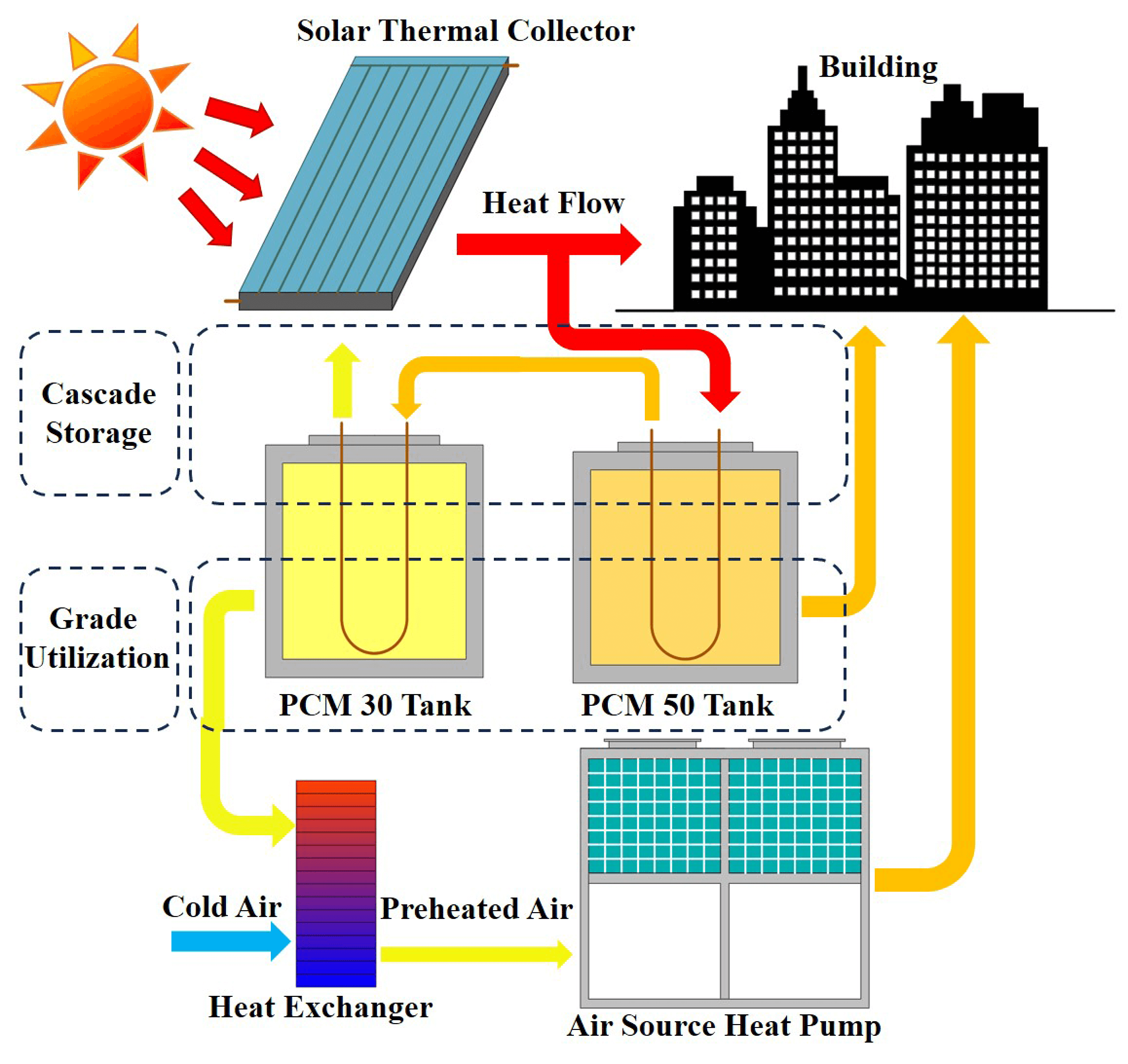
The two-stage phase change heat storage and supply (TPCHSS) system represent an innovative approach to building heating that integrates solar energy utilization with heat pump technology through advanced thermal storage mechanisms. As illustrated in Fig. 1, this sophisticated system incorporates five primary components: a solar energy collection device, a thermal storage water tank, an air-source heat pump device, a heat exchange apparatus, and a cascaded phase change material thermal storage configuration with distinct temperature characteristics. The system’s operational framework establishes a solar thermal collection subsystem through the synergistic combination of the solar collector and water tank. Within the thermal transfer process, the working fluid circulating from the water tank initially interacts with the higher temperature PCM50 storage device, which operates at a phase transition temperature of 50°C, before subsequently transferring thermal energy to the lower temperature PCM30 storage device with a phase change threshold of 30°C. The system’s thermal management strategy allocates specific functions to each PCM device: the PCM50 module directly supplies heating capacity for building climate control, while the PCM30 device performs a crucial role in preconditioning ambient air before its introduction to the air-source heat pump system. This pre-conditioned air stream subsequently undergoes thermal exchange processes within the heat pump’s evaporator device. The incorporation of the air source heat pump as an auxiliary heating component ensures system reliability and maintains consistent thermal output, thereby guaranteeing the TPCHSS’s operational stability under varying environmental conditions. This configuration demonstrates an efficient integration of renewable energy utilization with thermal storage technology.
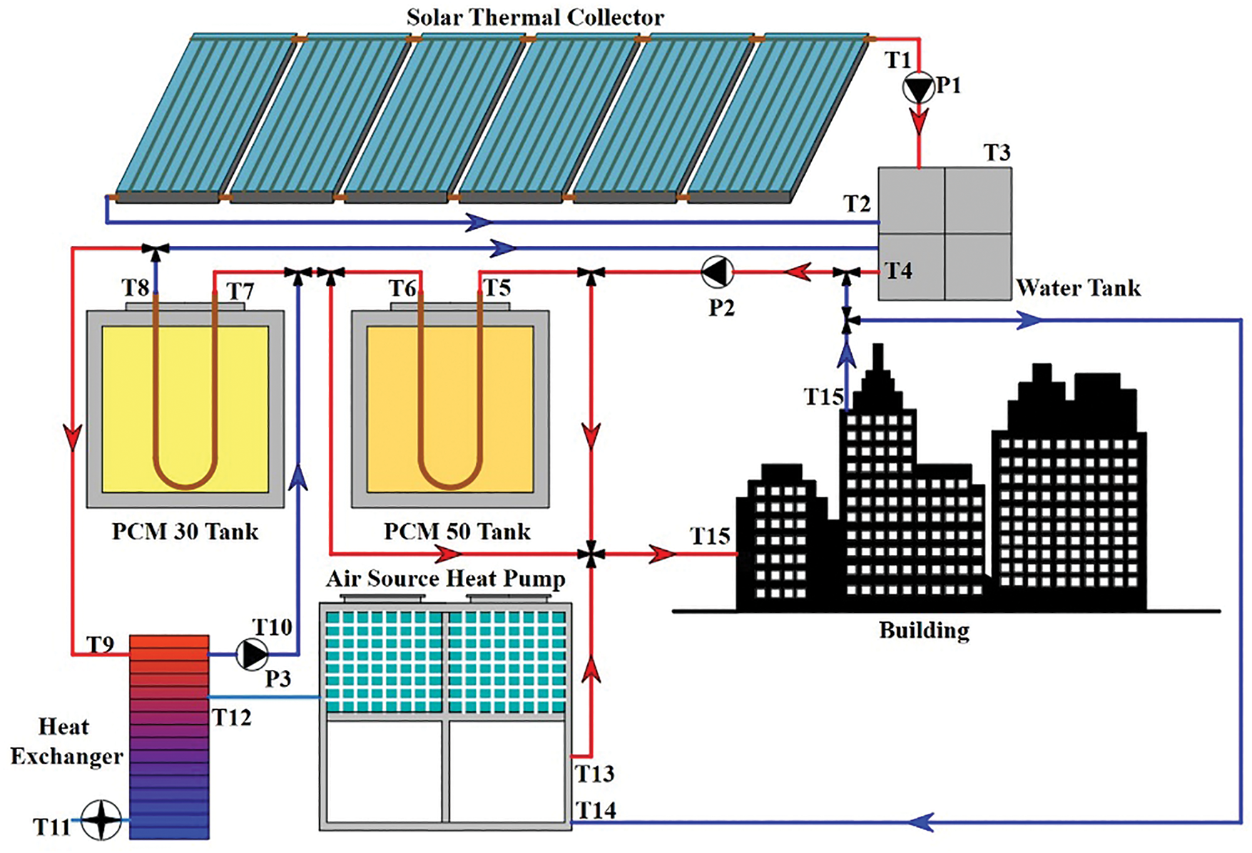
Figure 1: Structure of the two-stage phase change heat storage and supply (TPCHSS) system
The computational model of the TPCHSS was implemented utilizing the TRNSYS simulation platform, incorporating meteorological parameters specific to the Shenyang geographical area. Fig. 2 presents the comprehensive schematic diagram of the TPCHSS simulation architecture. The fundamental operational parameters governing the system’s simulation are systematically tabulated in Table 1. The thermophysical characterization of these PCMs was conducted through advanced analytical instrumentation. The thermal properties were precisely determined using two measurement techniques: a differential scanning calorimeter (DSC25, manufactured by TA Instruments, USA) with a temperature measurement accuracy of ±0.1°C, and a transient plane source thermal conductivity analyzer (supplied by Nanjing Dazhan Electromechanical Institute) demonstrating a measurement precision of ±3.0% for thermal conductivity assessment.
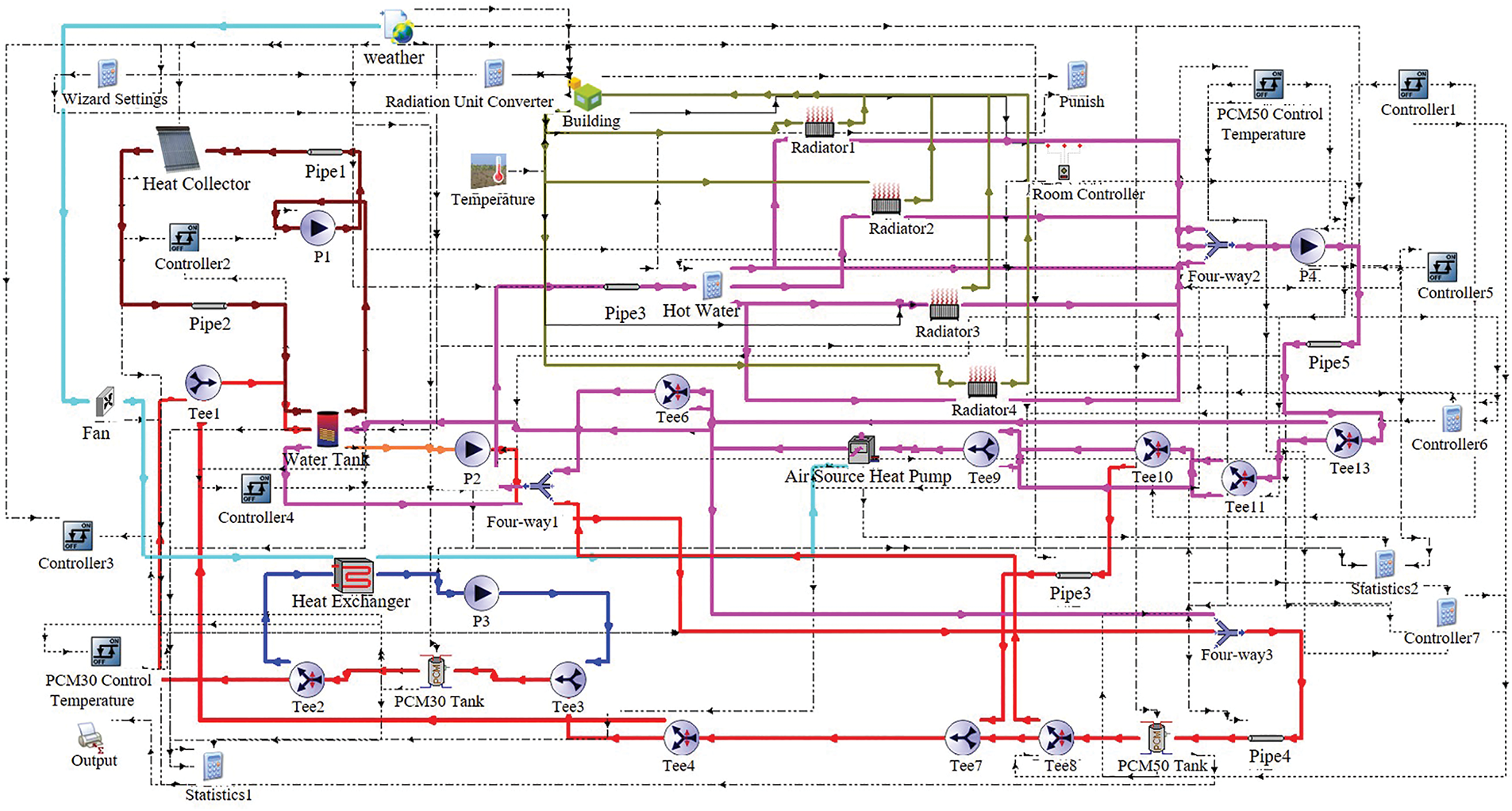
Figure 2: Simulation model diagram of TPCHSS system
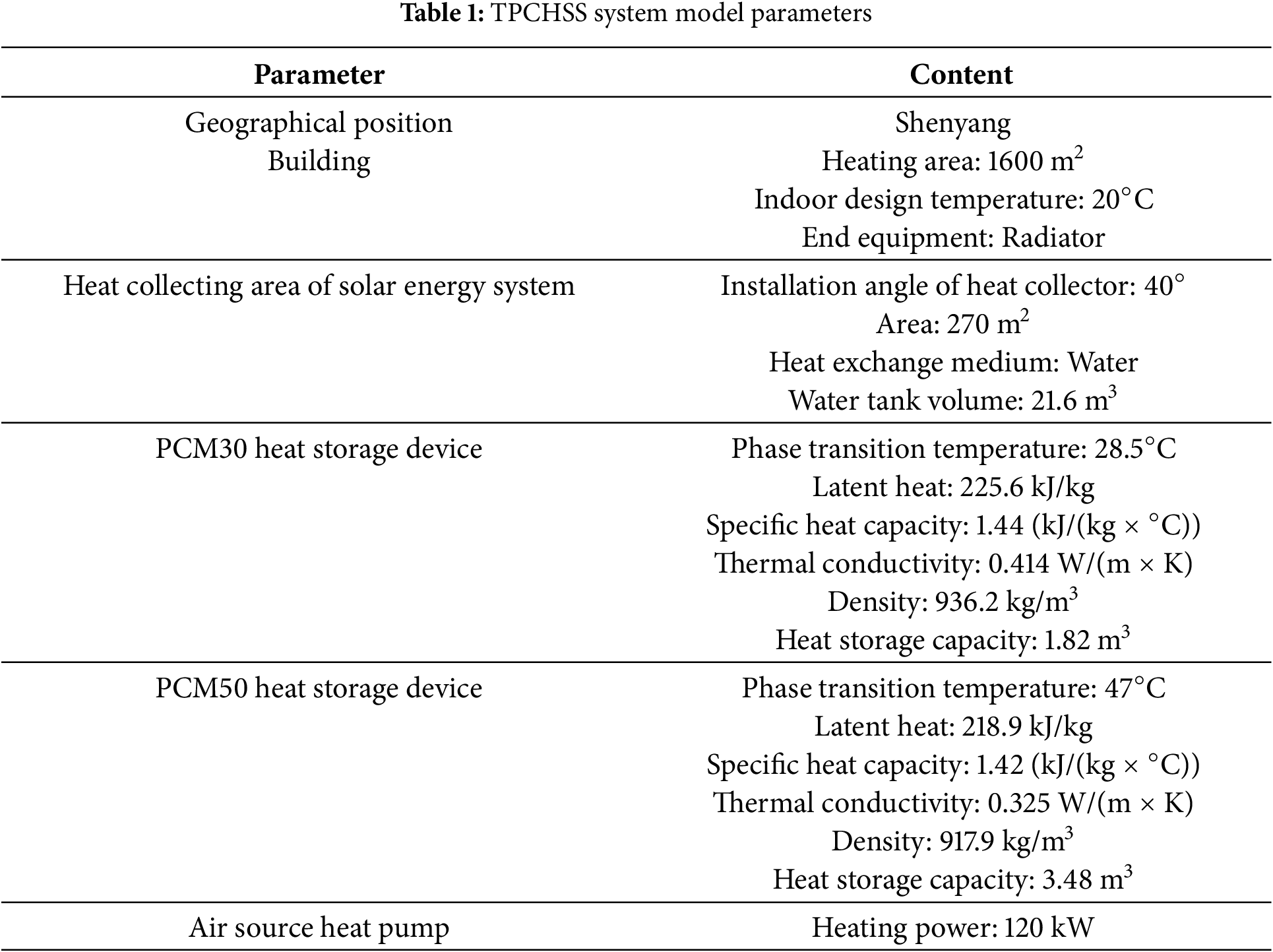
For the calculation formula of heat collecting area of solar energy system [34]:
where, Asolar is the heat collecting area of solar energy system, m2. QD is the building heat load, kWh. Ss is the average daily solar radiation, kWh/(m2·d). f is the solar guarantee rate, 0.2~0.4. ηc is the daily efficiency of solar collector, %. ηl is the loss rate of solar collector, %.
For the calculation formula of air source heat pump power:
where, PASHP denotes the power of the air source heat pump, kW. β1 is the equipment coefficient, 0.75~1.0. β1 is the safety coefficient, 1.05~1.10.
For the heat storage capacity of heat storage device:
where, VPCM is the heat storage capacity of heat storage device, m3. q is the heat storage density of PCM, kWh/kg. ρ is the density of PCM, kg/m3.
2.2 PCM Heat Storage Device Model
The PCM heat storage model, referred to as Type 211, is implemented using FORTRAN within the TRNSYS simulation environment. The mathematical model of the phase change storage unit is shown in Fig. 3. The primary assumptions and governing formulas for this model are as follows [35]:
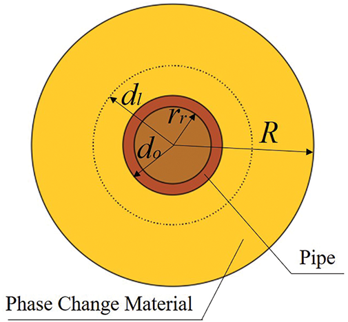
Figure 3: Mathematical model of phase change storage unit
Several fundamental assumptions were established to facilitate the thermal analysis and modeling of the phase change processes within the system:
1. Isothermal Phase Transition: The phase transformation of the PCMs is modeled as an isothermal process, maintaining a constant temperature during the complete phase transition period.
2. Unidirectional Fluid Flow: The heat transfer fluid circulates through the system in a single pass configuration, ensuring a consistent flow pattern without recirculation within individual passes.
3. Uniform Thermal Exchange: The thermal interaction between the PCMs and the heat transfer fluid is considered uniformly distributed across all heat exchange tubes, assuming identical heat transfer characteristics for each parallel flow path.
4. Convective Effects Negligibility: Internal convective heat transfer within the PCM medium is disregarded, with heat transfer assumed to occur primarily through conduction mechanisms.
5. Phase Independent Thermal Capacity: The specific heat capacity of the PCMs is considered invariant across different physical states, maintaining identical values in both solid and liquid phases.
6. Volume Stability: The model assumes negligible volumetric expansion of the PCMs during phase transitions, maintaining constant density throughout the thermal cycling process.
The format (5) for heat transfer fluid is as follows [35]:
where, rr represents the radius length of pipe, m. h represents the heat exchanger coefficient, W/(m·°C). Tm represents the temperature of flowing medium, °C. Tp represents the heat exchanger temperature, °C. Cpfm denotes the specific heat capacity of flowing medium, kJ/(kg·°C). mm denotes the mass flower rate of flowing medium, kg/h. t represents the operation time, h.
The format (6) for PCMs is as follows:
where, ρm represents the density of molten phase change materials, kg/m3. ρs represents the density of solidified phase change materials, kg/m3. Cppcm is the specific heat capacity of phase change materials, kJ/(kg·°C). R denotes the device radius, m. Tpcm represents the temperature of phase change materials, °C. do is the outer radius of the copper pipe, m. Hpcm is the latent heat of phase change materials, kJ/kg. dl indicates the melting degree of the phase change materials along the radial direction, m. Tmpcm denotes the phase change temperature, °C. When Tpcm = Tmpcm, take “+” during melting process and “-” during solidifying process.
2.3 System Operation Control Strategy
There are two operational modes of a TPCHSS system, namely cascade heat storage mode and staged heat release mode. The main control components in the two operational modes are the solar heat collection system, phase change heat storage device and air source heat pump. Among them, the operation of the solar heat collection system is based on the temperature difference control method [36]. The heat storage and heat release control of the phase change heat storage device is based on the inlet and outlet water temperature, which enables the phase change material to effectively store heat and release heat, and the water temperature to meet the heat demand. The operational modes of the TPCHSS system are divided into the following four types:
When T1-T3 ≥ 5°C, the water pump P1 starts to run. When the water tank temperature T3 ≥ 50°C, the solar heat collection system provides heat for the building. When the water tank temperature T3 ≥ 60°C, the water pump P3 starts to run, and the solar heat collection system sequentially stores heat for the PCM50 heat storage device and PCM30 heat storage device.
When T3 ≤ 55°C, the PCM50 heat storage device stops heat storage. When T3 ≤ 40°C, the PCM30 heat storage device stops heat storage, and the solar heat collection system stops heating the building. The TPCHSS system uses the PCM50 heat storage device to release heat for building heating.
When the outlet water temperature of the PCM50 heat storage device is less than 40°C, the TPCHSS system only uses an air source heat pump to provide heat for the building.
When the air source heat pump is running, if the internal temperature of the PCM30 heat storage device is 10°C higher than the outdoor air temperature, the PCM30 heat storage device will preheat the outdoor air through the heat exchanger and then deliver it to the air source heat pump evaporator. If the temperature difference between the inside temperature of the PCM30 heat storage device and the outdoor air is less than 5°C, the PCM30 heat storage device stops preheating the outdoor air.
3.1 Hooke-Jeeves Optimization Method
As illustrated in Fig. 4, the optimization process follows the Hooke-Jeeves method. Given the complex interdependencies among system parameters, identifying the optimal set of parameters to enhance system performance is a challenging task. To overcome this difficulty, the GenOpt optimization method is used to determine the best system parameters, effectively handling the complexity of parameter interactions. The TrnOpt module functions as a bridge connecting TRNSYS and GenOpt, facilitating the optimization process by identifying pertinent optimization variables, algorithms, and objective driven functions. In this research, the Hooke-Jeeves optimization algorithm, alternatively referred to as the step-by-step acceleration or pattern search method, was selected. The fundamental concept underlying this algorithm revolves around locating the minimum of a quadratic function, thereby determining the point on the curve that corresponds to the lowest value.
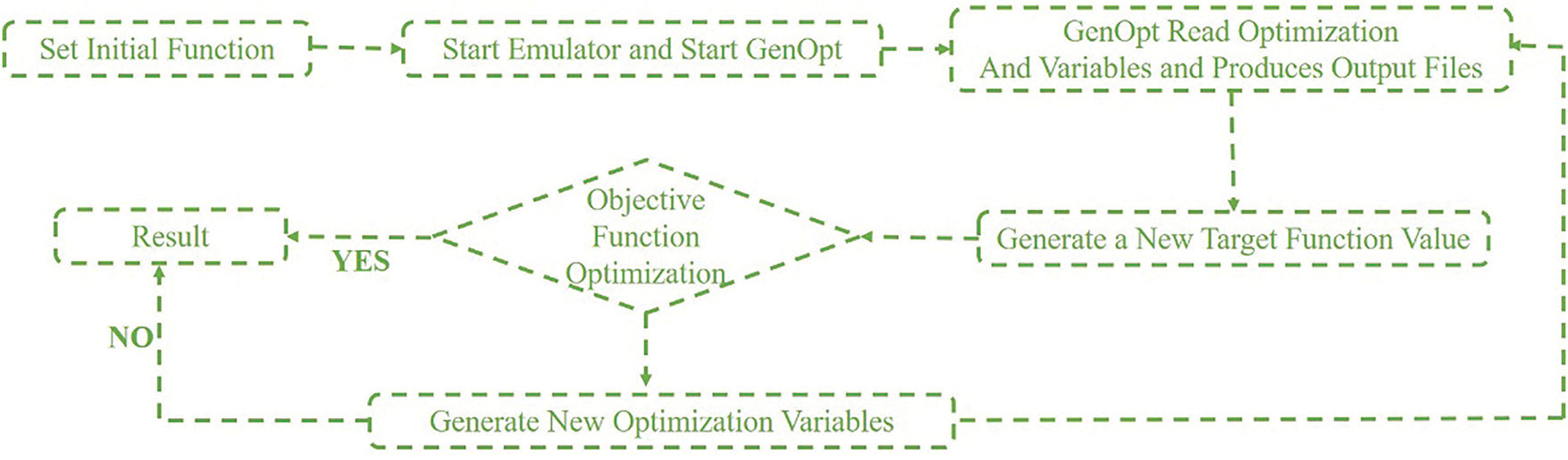
Figure 4: Hooke-Jeeves optimization flowchart
The objective function formulated for the system optimization is characterized as a weighted combination, comprising 50% of the annual operational cost and 50% of the total carbon emissions. The key variables subjected to optimization encompass the heat collection area of the solar energy system, the heating capacity of the air source heat pump, the thermal storage capacity of the PCM50 heat storage device, and the thermal storage capacity of the PCM30 heat storage device.
In order to prevent the indoor comfort from being affected by the continuous decrease of room temperature, the penalty rules defined are as follows:
A penalty mechanism is implemented to ensure that the room temperature reaches 20°C within one hour of system operation. If this condition is not met, a penalty of 15,000 CNY per hour is applied for each hour the room temperature remains below the specified threshold. The deposit rate is fixed at 0.055. This penalty is integrated into the annual cost function of the heating system to reflect its financial implications. Given the substantial influence of the penalty, the optimization algorithm is designed to prioritize system parameters that prevent the room temperature from falling below 20°C. The calculation for this penalty is expressed in Formula (7) as follows [37]:
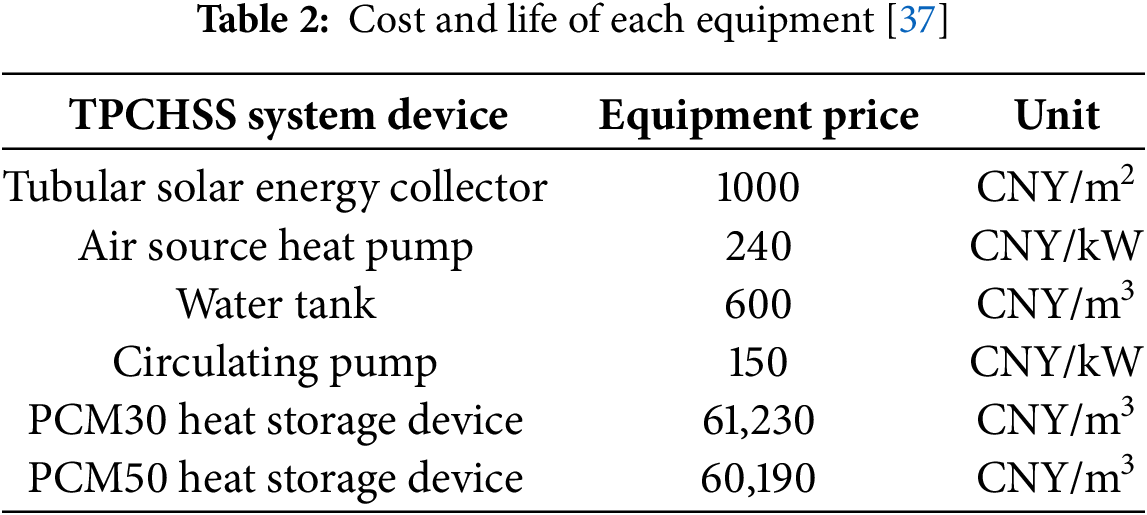
where, Ct represents the TPCHSS system annual cost, CNY/year. L represents the lifespan, 20 years. Li represents the TPCHSS system initial investment, CNY. CR represents the system running cost, CNY/year. Table 2 shows the cost and lifespan of each device in the TPCHSS system [37].
3.2 Operation Structure of Different Heating Systems
Based on the optimized parameters of the TPCHSS system, the effects of heat storage devices at different temperatures on the performance of the heating system are studied. Therefore, the PCM50 heat storage and supply (PCM50HSS) system, PCM30 heat storage and supply (PCM30HSS) system and clean heating (CH) system are constructed as shown in Figs. 5–7. The PCM50HSS system uses a PCM50 heat storage device to store heat, and the air source heat pump does not have outdoor air preheating conditions. The PCM30HSS system uses the PCM30 heat storage device to store heat that is used to preheat outdoor air entering the air source heat pump. The CH system uses an air source heat pump to provide heat for buildings.
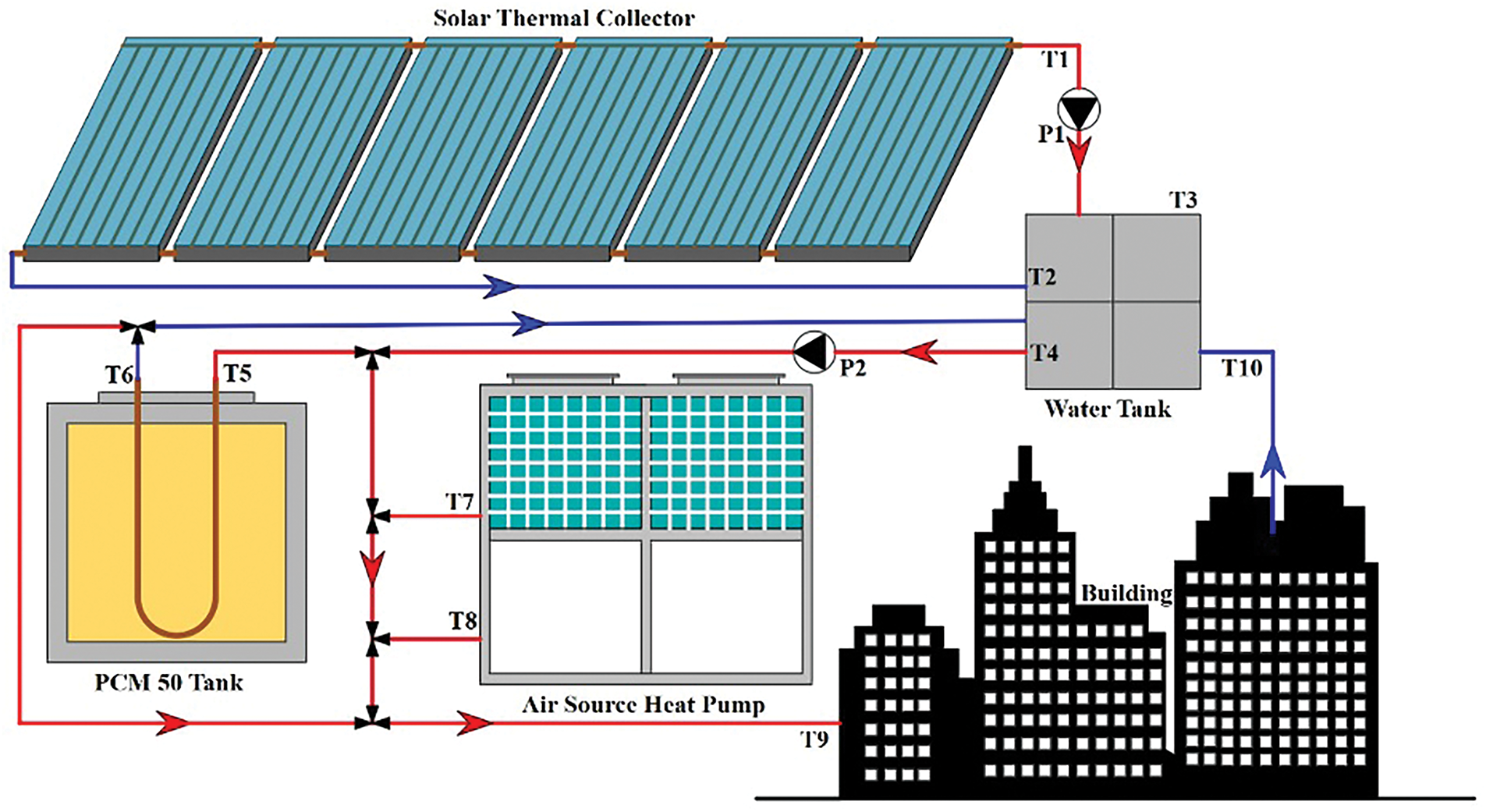
Figure 5: Structure of PCM50 heat storage and supply (PCM50HSS) system
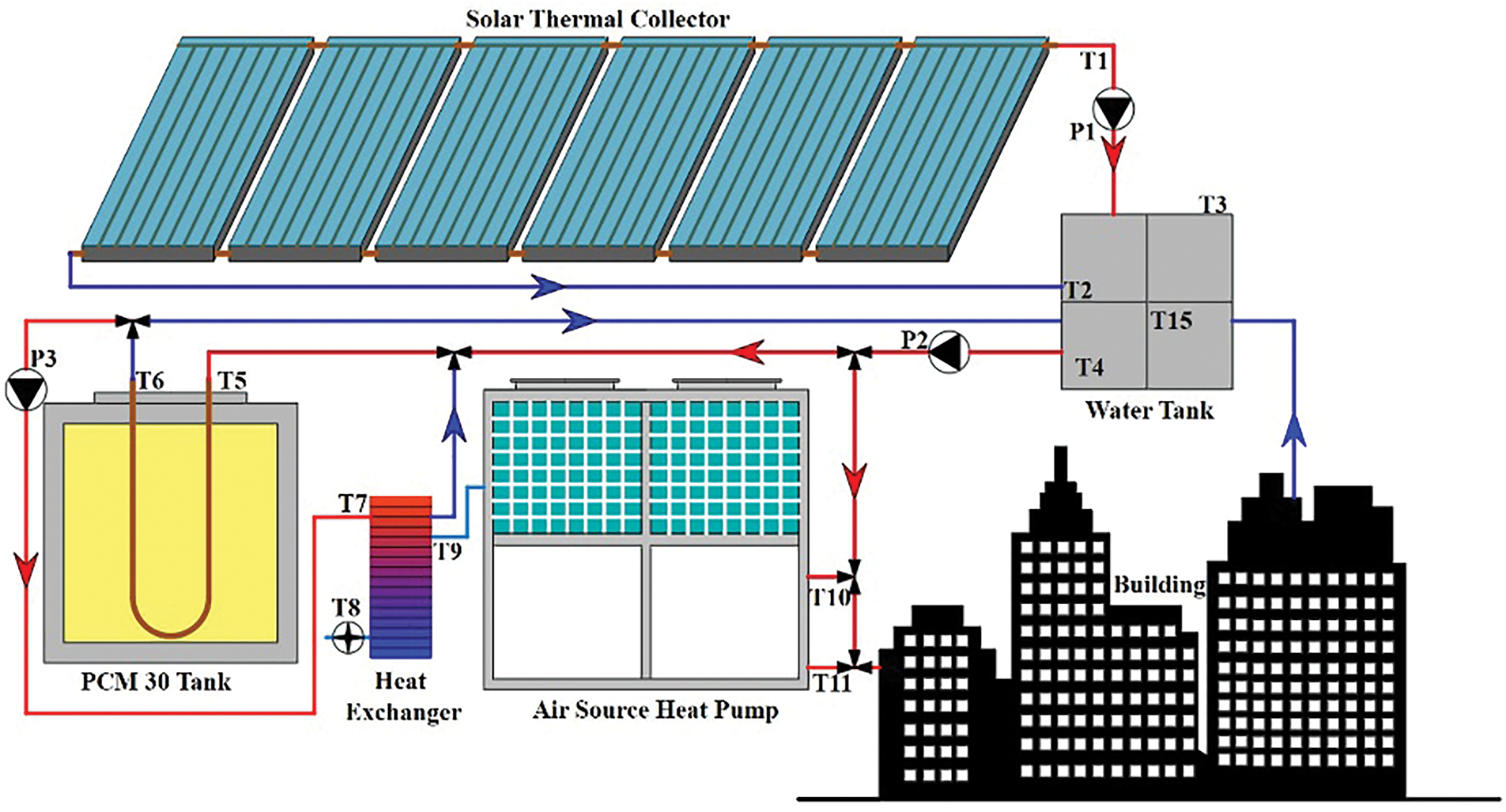
Figure 6: Structure of PCM30 heat storage and supply (PCM30HSS) system
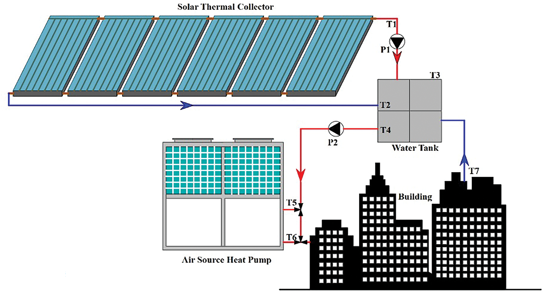
Figure 7: Structure of clean heating (CH) system
The Levelized Cost of Heat (LCOH) serves as a crucial economic metric for assessing the financial viability and long-term sustainability of the TPCHSS. This comprehensive indicator quantifies the total expenditure associated with producing one kilowatt-hour (kWh) of thermal energy throughout the system’s operational lifespan. The LCOH calculation encompasses four primary cost components: the initial capital investment for system installation, ongoing operational expenditures, periodic maintenance requirements and quantity of heat production. The operational cost component is specifically derived from the system’s energy consumption profile, which is subsequently multiplied by the prevailing electricity tariff rates. This relationship can be mathematically represented by Formula (8), which provides a systematic framework for calculating the LCOH [37]. The formula integrates both fixed and variable costs, offering a holistic perspective on the system’s economic performance by distributing total expenditures over the system’s energy output.
where, l denotes a specific year within the lifespan of the device in TPCHSS heating system, year. Cm is the maintenance cost of the device in TPCHSS heating system, CNY. Qg is the heat generated by TPCHSS system, kWh. In this study, the annual maintenance cost is assumed to be 1% of the system construction cost. A discount rate of 0.03 is applied. The system’s running cost CRun primarily arises from the electricity bill of water pumps and the air source heat pump. The calculation of operating expenses is provided in Formula (9) through Formula (13) [37].
where, Pp represents the power of the circulating pump, kW. Pn represents the time-of-use electricity price, CNY/kWh. The peak and off-peak electricity prices are referenced in [34]. t is the device running time, h.
4.2 Environmental Evaluation Model
The emission of carbon dioxide produced by the TPCHSS system is used as the environmental analysis indicator. The calculation Formula (14) of carbon dioxide emission of TPCHSS system is as follows [37–40]:
where, MLC represents life cycle carbon dioxide emission, kg/m2. 2.493 is the pollutant carbon dioxide emission coefficient. ηt is the thermal power generation efficiency of thermal power plant, 35%. ηpn is the transmission efficiency of power network, 92%. ηte is the thermoelectric conversion efficiency, 99%. S represents the building heating area, m. MASHP is the carbon emissions in manufacturing stage of air source heat pump, 456 kg/kW [38]. MPCM is the carbon emissions in manufacturing stage of phase change material, 50~100 kg/kWh [39]. QPCM is the heat storage of phase change material, kWh. MSC is the carbon emissions in manufacturing stage of solar thermal collector, 100~200 kg/m2 [38,40]. SSC is the laying area of solar thermal collector, m2. Mm is the system carbon emissions in the maintenance phase, kg. ηm is the System maintenance coefficient, 1%. Mm is the carbon emission of the system in the scrapping stage., kg. ηs is the System scrap coefficient, 5%.
To validate the operational efficacy of the proposed two-stage thermal energy storage system, an experimental setup was meticulously constructed. As depicted in Fig. 8, the testing apparatus comprises several critical components. The heating temperature of the constant temperature water bath was set to 80°C. During experimental operations, the heated fluid initially circulated through the PCM50 heat storage device, subsequently flowing through the PCM30 heat storage device. The comprehensive monitoring system integrated within the experimental setup continuously captured thermal performance data, including temperature measurements at both the inflow and outflow points of each storage heat device, as well as internal temperature variations within the PCM containment structures. As depicted in Fig. 9, the heat storage devices were undergoing state changes at temperatures of 30°C and 50°C, respectively.
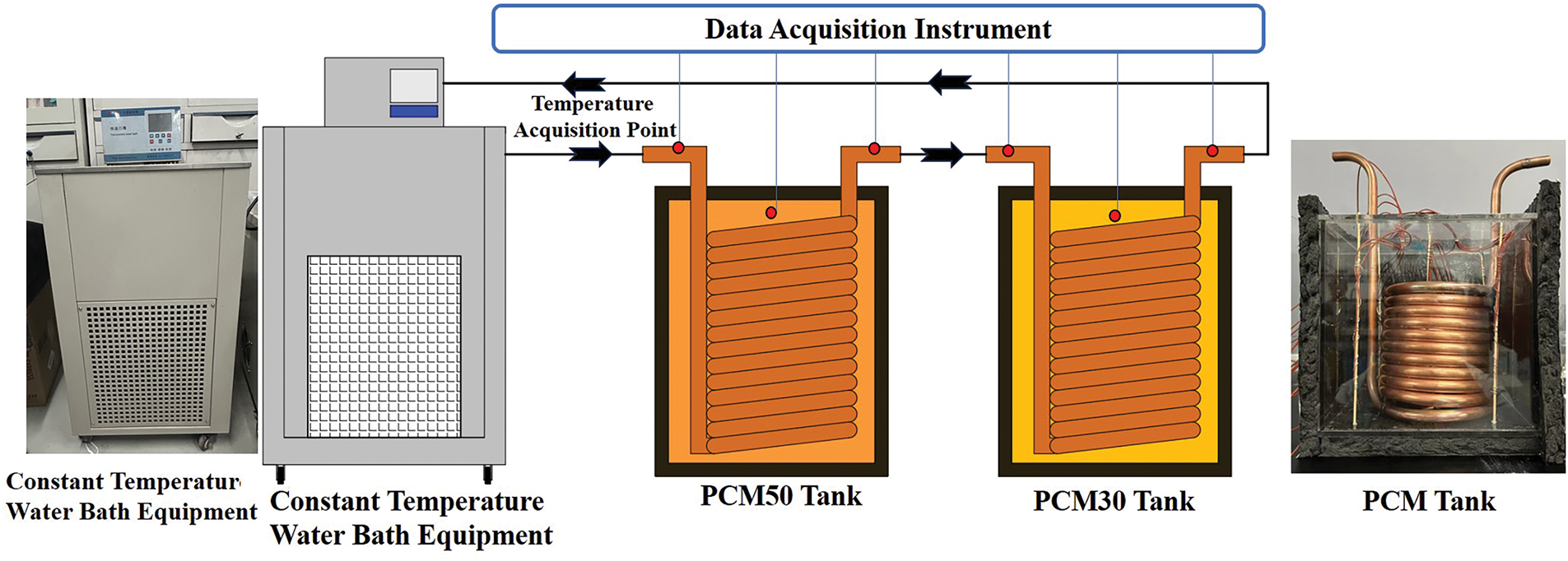
Figure 8: Test platform of two-stage heat storage device
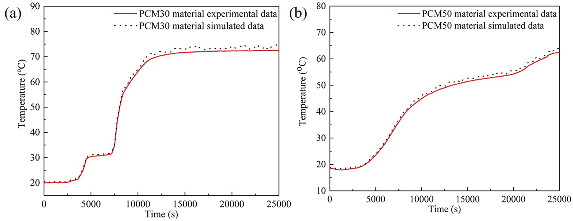
Figure 9: Comparison of experimental and simulated temperature data of PCMs: (a) PCM30 material temperature; (b) PCM50 material temperature
Meanwhile, the simulated temperature change of phase change materials had a similar trend to that observed the experimental data. Fig. 10 shows that there was a similar change in trend between the model data and the experimental data regarding the temperature difference between the inlet and outlet of the two heat storage devices. To comprehensively assess the predictive accuracy and operational reliability of the computational model for the two-stage thermal energy storage system, a rigorous quantitative evaluation framework was established. The experimentally obtained measurements are denoted as xi, while their corresponding simulated counterparts are represented as yi. The parameter p indicating the total number of the experimental dataset. This mean absolute error (MAE) is mathematically defined through the following formulation [41]:
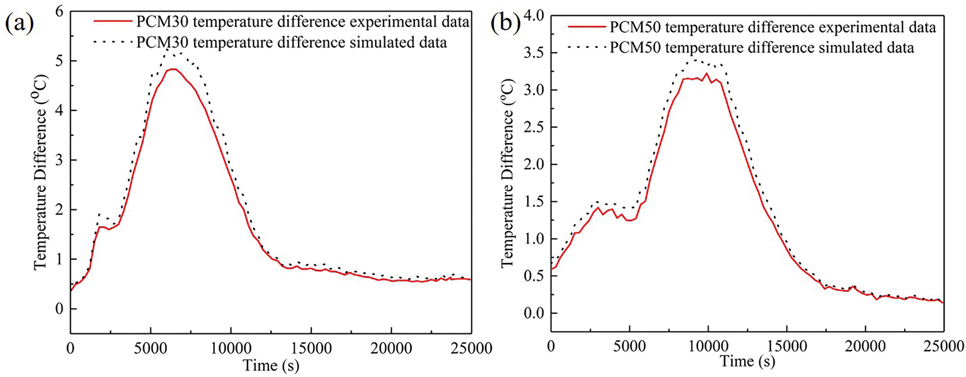
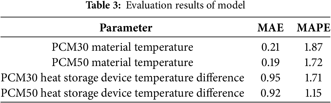
Figure 10: Comparison of experimental and simulated temperature difference data between inlet and outlet of heat storage device: (a) PCM30 heat storage device; (b) PCM50 heat storage device
The relative error between
The quantitative assessment of model performance, as presented in Table 3, reveals significant alignment between computational simulation and experimental observations. The calculated values of both statistical metrics demonstrate that the model is performing excellent.
As demonstrated in Fig. 11, the thermal energy storage performance of the PCM50 heat storage device within the TPCHSS system significantly surpasses that of the PCM30 heat storage device, with the former exhibiting a 34.8% higher heat storage capacity than the latter. This disparity was due to the fact that the solar energy collection system prioritized transferring thermal energy to the PCM50 heat storage device before redirecting heat to the PCM30 heat storage device. The PCM50 heat storage device directly supplies heat to the building, while the PCM30 heat storage device primarily acts as a preheating device for the air source heat pump’s intake air, thereby improving the heat pump’s overall thermal efficiency. This operational strategy facilitates the graded utilization of solar energy, optimizing energy distribution across different temperature levels.
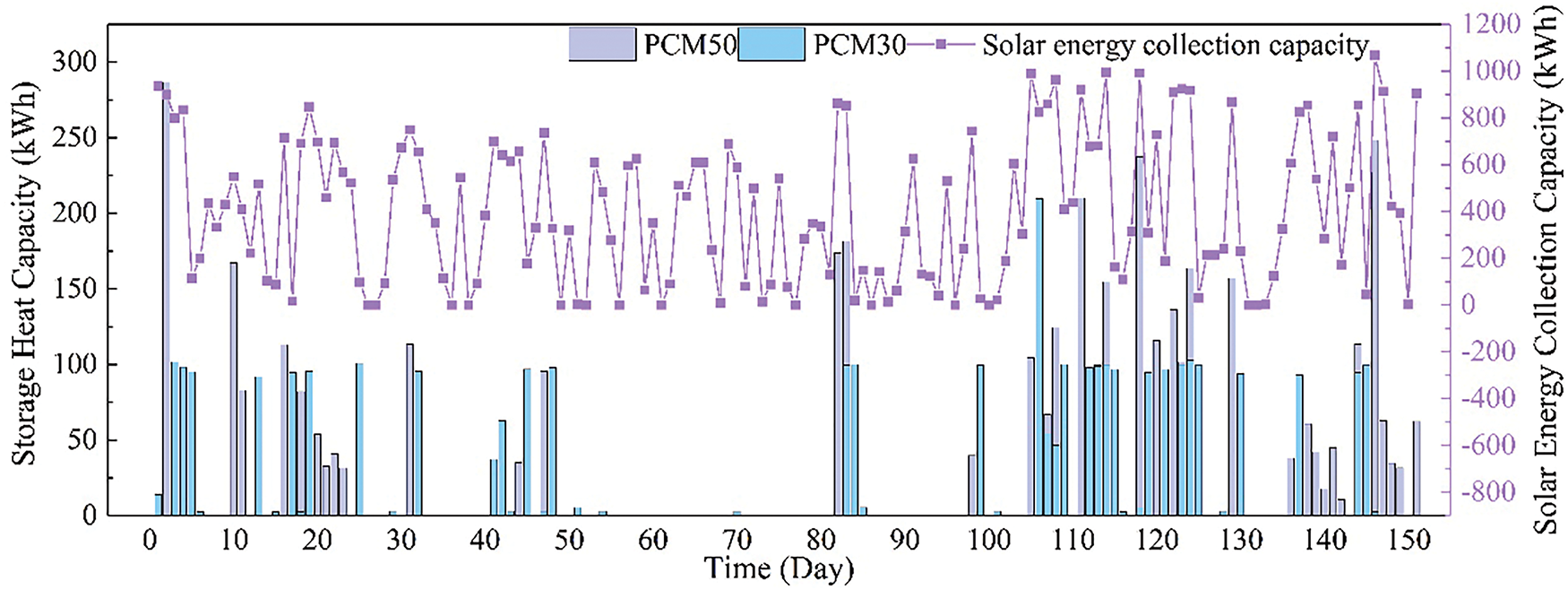
Figure 11: TPCHSS system heat storage change
Throughout the operational period, the TPCHSS system exhibited relatively stable solar energy collection during the initial phases, but experienced more pronounced fluctuations in the later stages. These variations in solar irradiance during the latter phase prevented the water tank temperature from reaching the 60°C threshold required to activate heat storage in the phase change devices. The TPCHSS system’s total solar energy collection amounted to 61,162.8 kWh, with the PCM50 and PCM30 heat storage devices storing 4334.2 kWh and 3215.3 kWh, respectively. This corresponds to 7.1% and 5.3% of the total collected solar energy being stored in the PCM50 and PCM30 heat storage devices, respectively. The remaining thermal energy was either utilized directly for building heating or retained within the water tank for subsequent use.
Fig. 12 illustrates the variation in heat release from the phase change heat storage devices in the TPCHSS system. The PCM50 heat storage device released the highest amount of heat. However, phase change heat storage devices released relatively little heat during the heat release process. This was primarily because the temperature of the water tank in the solar energy collection system was insufficient to meet the heat storage temperature requirements of the phase change heat storage devices, although it was adequate for meeting the building heating requirements. As a result, phase change heat storage devices did not store significant amounts of heat. During the non-heating period of the solar energy collection system, the heat released by the PCM50 heat storage device was 3475.9 kWh, while the PCM30 heat storage device released 3107.5 kWh. The PCM30 heat storage device was primarily used to preheat outdoor air entering the evaporator of the air source heat pump. The heat conversion efficiency of the PCM50 heat storage device was 80.2%, while that of the PCM30 heat storage device was 96.7%. Because when the outlet water temperature of the PCM50 heat storage device was less than 40°C, the heat release of the PCM30 heat storage device stopped, and the more heat released, the lower the outdoor air temperature. Therefore, the conversion efficiency of the PCM30 heat storage device was higher than that of the PCM50 heat storage device. In summary, the TPCHSS system effectively achieved the graded utilization of stored solar energy.
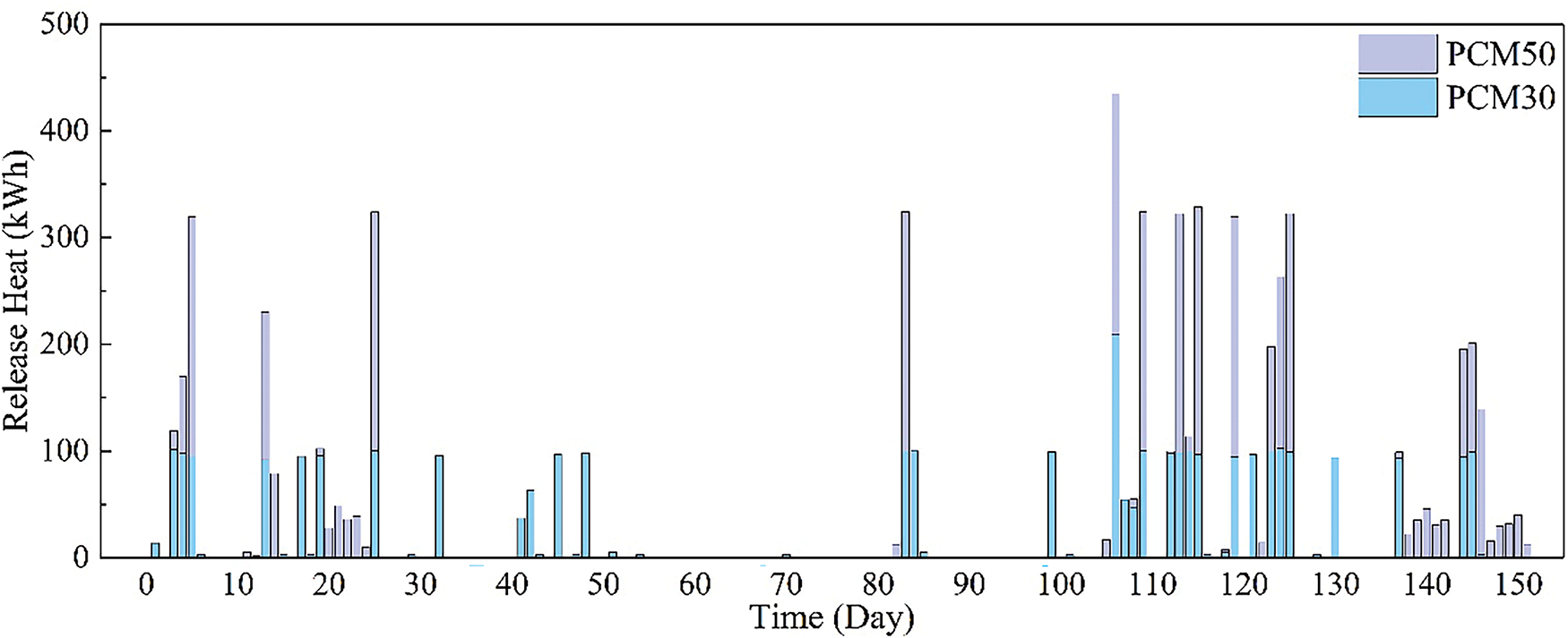
Figure 12: TPCHSS system heat release change
Fig. 13 illustrates the variation in heating output for each heating device within the TPCHSS system. The system predominantly depends on direct solar heating as its primary heat source. To address the inherent intermittency and instability of solar energy, the PCM50 heat storage device plays a critical role by storing surplus solar thermal energy for later use. However, during periods of low solar irradiance, when the solar heat collection system cannot generate sufficient heat and the phase change heat storage devices are unable to store energy, the system’s heating capacity becomes compromised. Under such conditions, the air source heat pump serves as a supplementary heating source, ensuring the system’s thermal stability and reliability. Analysis of the system’s performance reveals that the PCM50 heat storage device contributed 3475.9 kWh of direct heat supply, while the air source heat pump and the solar heat collection system provided 94,890.4 kWh and 49,250.9 kWh, respectively. Since the thermal energy stored in the phase change devices is ultimately derived from the solar collection system, the total effective solar heat supply amounts to 52,726.8 kWh, representing 35.7% of the system’s total heat output. Therefore, the TPCHSS system should focus on optimizing structural parameters to increase the proportion of solar heating and reduce reliance on electric auxiliary heating.
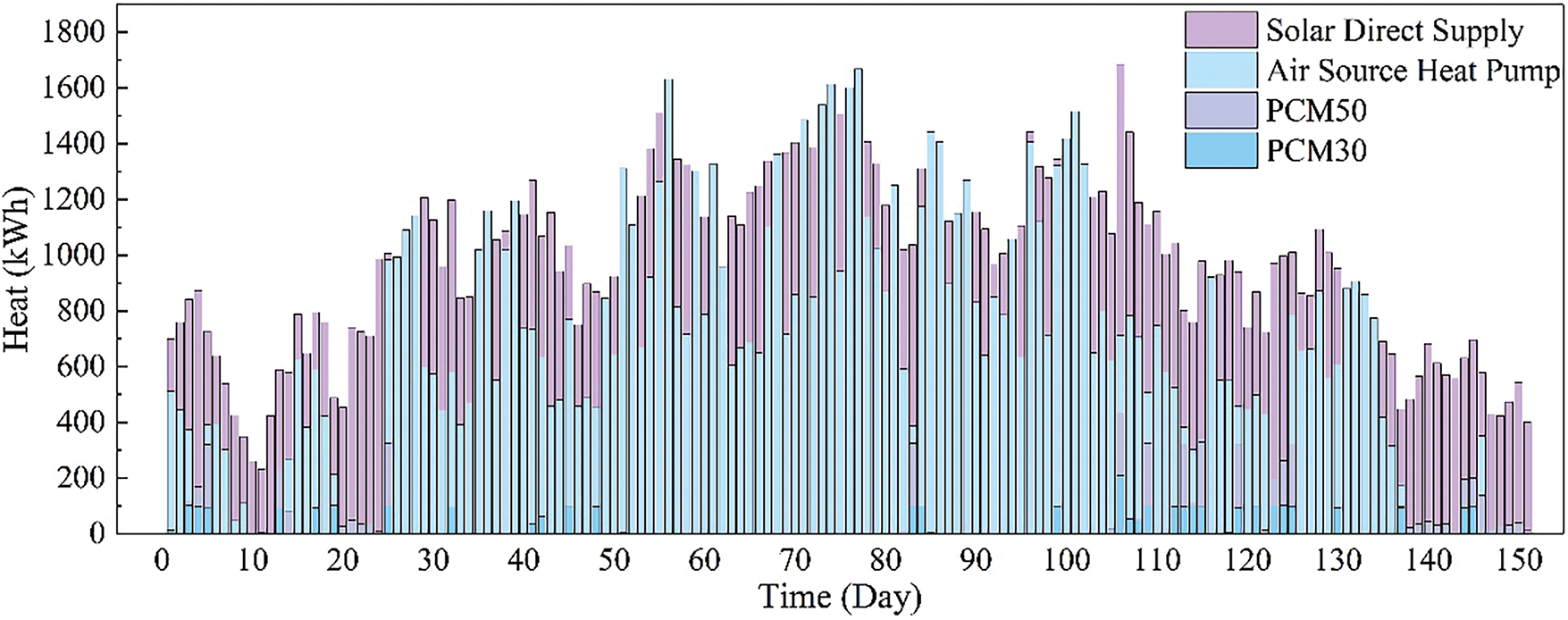
Figure 13: TPCHSS system heat supply change
5.3 Influence of Structural Parameter on System Performance
To assess the effect of system design parameters on operational efficiency, an analysis was conducted to examine the relationship between the solar heat collection area and the performance of the TPCHSS system. As demonstrated in Fig. 14a, the energy consumption of the system exhibited a declining trend as the solar heat collection area expanded. This inverse correlation can be attributed to the increased availability of solar thermal energy, which reduced the system’s dependence on auxiliary power sources, thereby lowering its overall energy demand. In contrast, Fig. 14b reveals that the LCOH for the TPCHSS system increased proportionally with the enlargement of the solar heat collection area. This trend is primarily driven by the higher initial capital expenditures and ongoing operational expenses associated with larger solar collection systems. These findings highlight a critical trade off in system design: while expanding the solar heat collection area enhances energy efficiency and reduces operational energy consumption, it simultaneously elevates the economic costs of the system. Therefore, optimizing the solar heat collection area requires a balanced approach that considers both energy performance and economic feasibility.
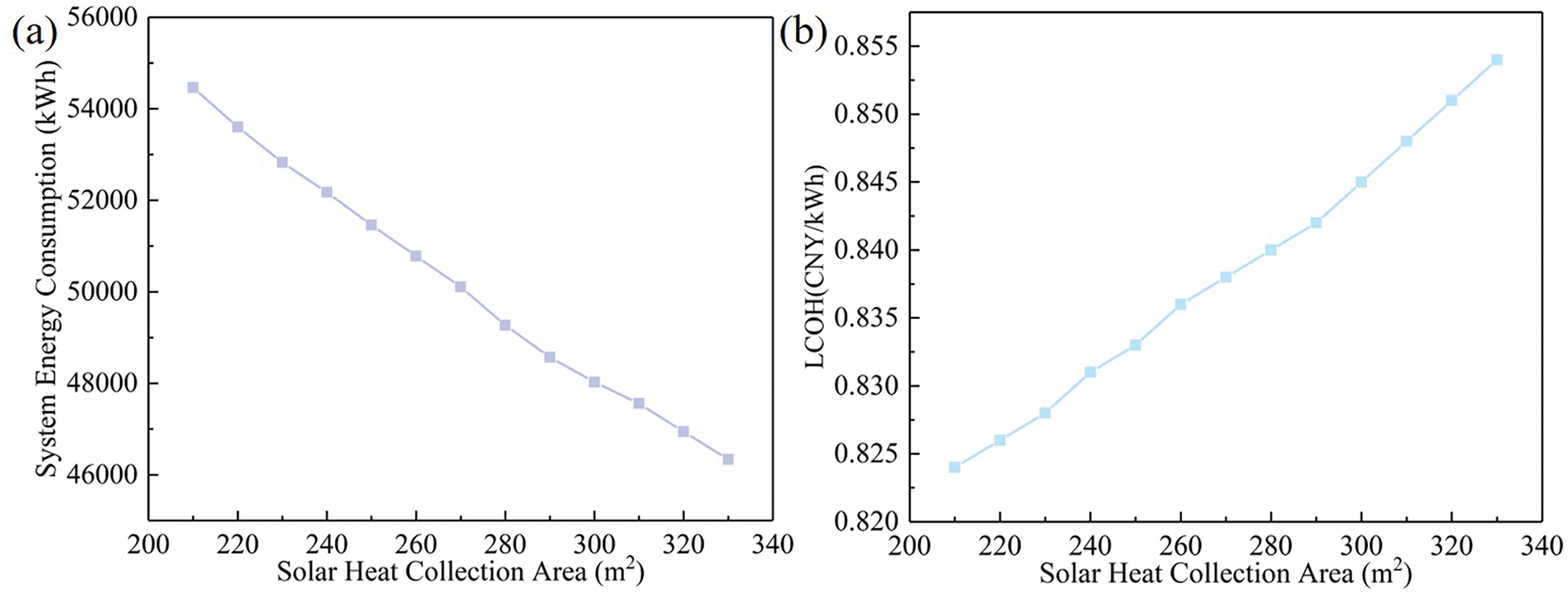
Figure 14: Variation data of solar heat collection area: (a) System energy consumption; (b) LCOH
The impact of air source heat pump power on the performance of the TPCHSS system was further investigated to understand its influence on energy consumption and economic metrics. As illustrated in Fig. 15a, the system’s energy consumption initially rose with increasing heat pump power but eventually stabilized. Since the building’s heat demand remains constant, the system’s energy consumption plateaued when the heat pump power reached 110 kW, beyond which additional power provided diminishing in terms of heat output. Conversely, Fig. 15b demonstrates that the LCOH of the TPCHSS system exhibited a steady increase as the air source heat pump power grew. This upward trend is primarily driven by the higher capital and operational costs associated with larger heat pump devices. Increased power capacity necessitates more robust equipment, greater installation expenses, and elevated maintenance requirements, all of which contribute to higher overall system costs. These results underscore the importance of selecting an optimal heat pump power rating that balances energy efficiency with economic viability. While higher power capacities can enhance system performance, they also lead to increased costs without proportional benefits in heat supply, particularly when the building’s thermal demand is fixed.
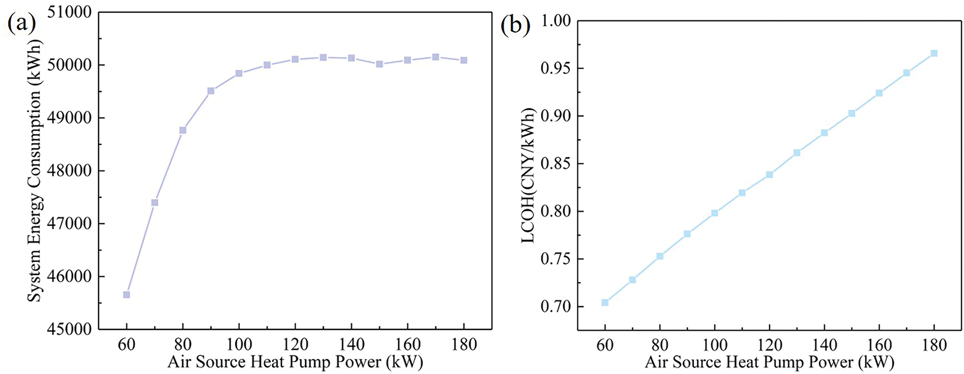
Figure 15: Variation data of air source heat pump power: (a) system energy consumption; (b) LCOH
5.4 System Optimization Results
The system parameters of the TPCHSS were optimized using the Hooke-Jeeves algorithm. The optimized TPCHSS (OTPCHSS) system parameters are as detailed in Table 4. The solar thermal collection surface area experienced a substantial expansion of 77.8%, while the power of the auxiliary heat pump was reduced by 41.7%. The heat storage devices underwent volumetric reductions, with the PCM50 and PCM30 heat storage devices decreasing by 8.1% and 12.1%, respectively. Fig. 16a revealed a marked 28.2% reduction in the OTPCHSS system’s daily energy consumption. This improvement is primarily attributed to the increase of solar thermal collection surface area. As shown in Fig. 16b, the energy consumption of the air source heat pump was reduced. This was because the heating time of the air source heat pump was reduced. During the entire heating period, the total energy consumption of the optimized air source heat pump decreased by 31.1%. The reduction in energy consumption of the optimized air source heat pump was due to the increase in the optimized solar heat collection area. As shown in Fig. 16c, the heat collection capacity of the solar energy collection system of the optimized TPCHSS system was significantly increased by 48.5%. As illustrated in Fig. 16d, the enhanced heat collection capacity of the solar energy system has led to a partial increase in the operating time of the water pump. Consequently, the energy consumption of the water pump in the optimized TPCHSS system has also risen. Specifically, the total energy consumption of the water pump in the optimized system increased by 47.7%. As shown in Fig. 16e, the coefficient of performance (COP) of the optimized air source heat pump was reduced, while the heating duration of the optimized TPCHSS system was shortened. The COP of the optimized air source heat pump was reduced by 1.3%. This was due to the reduction of the thermal storage capacity of the PCM30 heat storage device, which shortened the time for preheating outdoor air entering the air source heat pump. As shown in Fig. 16f, the heat supply from solar energy in the OTPCHSS system increased, while the heat output from the air source heat pump decreased. According to the analysis, the conversion efficiency of the PCM50 heat storage device and the PCM30 heat storage device in the OTPCHSS system were 86.9% and 94.3%, respectively. The solar direct heat supply in the OTPCHSS system was 80,279.9 kWh, accounting for 52.2% of the total heat supply in the TPCHSS system. Compared with the TPCHSS system, the total solar heating capacity of the OTPCHSS system has been increased by 46.2%. Compared with the TPCHSS system, the optimized LCOH value was 0.742, a decrease of 11.9%, and the optimized CO2 emission was 545.6 kg/m2 which decreased by 9.9%. The Hooke-Jeeves optimization method aims at reducing the annual cost and carbon emissions of the system.
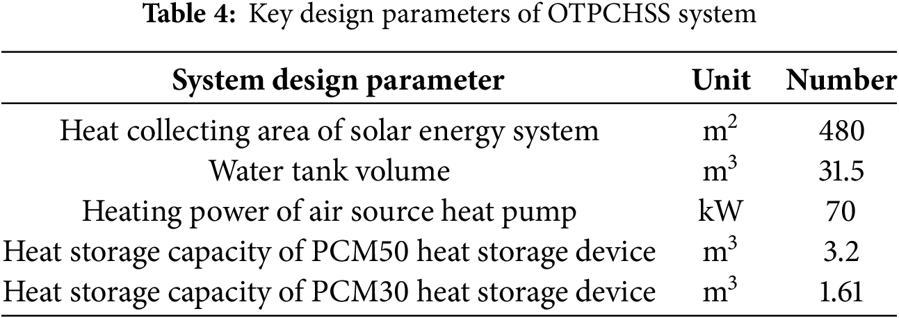
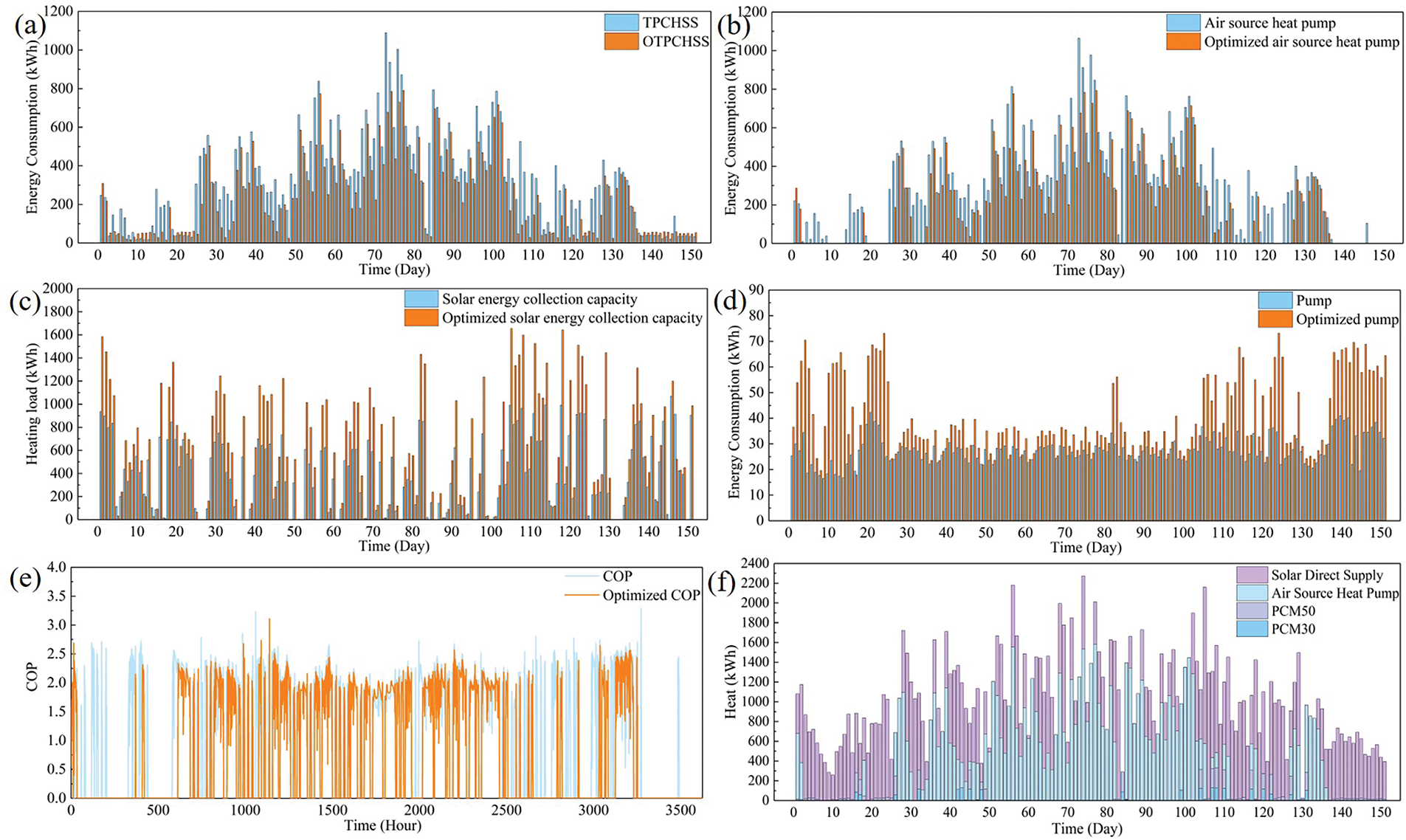
Figure 16: System optimization data: (a) system energy consumption; (b) air source heat pump energy system; (c) solar energy collection capacity; (d) pump energy consumption; (e) COP; (f) OTPCHSS system heat supply change
5.5 Comparative Analysis of Different Structural Systems
To evaluate the thermal performance characteristics of the OTPCHSS system under severe cold climate conditions, a comprehensive comparative analysis was conducted on various heating system configurations incorporating different phase change material thermal storage combinations. The energy consumption analysis, presented in Fig. 17a, reveals significant differences in system performance. The PCM50HSS configuration (lacking PCM30 heat storage device) demonstrated 10.2% higher energy consumption compared to the OTPCHSS system, while the CH system exhibited 14.5% greater energy usage. This performance disparity is primarily attributed to the reduced COP of air source heat pumps in severe cold conditions, where the absence of effective thermal storage significantly impacts system efficiency. Fig. 18 illustrated demonstrates the COP advantage of the OTPCHSS system over the PCM50HSS configuration. This improvement is directly correlated with the preheating capability of the PCM30 heat storage device, which elevates the temperature of incoming outdoor air. As shown in Fig. 19, the OTPCHSS system achieves a 14.5% higher average preheated air temperature compared to the PCM50HSS system. The OTPCHSS system maintained an average COP of 2.0, representing an 11.1% improvement over the PCM50HSS system’s average COP of 1.8. The comparative energy consumption analysis of the air source heat pump, presented in Fig. 17b, showed that the PCM50HSS system required 13.9% more energy than the OTPCHSS configuration, while the CH system consumed 14.7% more energy. As shown in Fig. 17c, the LCOH value of the OTPCHSS system was higher than that of the other three heating systems. This was because the other three heating systems had low construction investment. As shown in Fig. 17d, higher system energy consumption led to higher CO2 emissions. As a results, the CO2 emissions of the OTPCHSS system and PCM30HSS system were low, while the CO2 emissions of the PCM50HSS system and CH system were high.
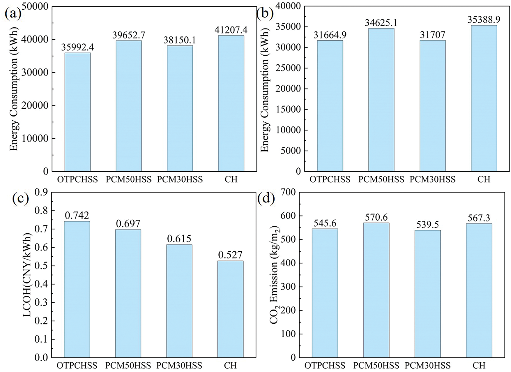
Figure 17: Different structure system data: (a) system energy consumption; (b) air source heat pump energy system; (c) LCOH; (d) CO2 emission
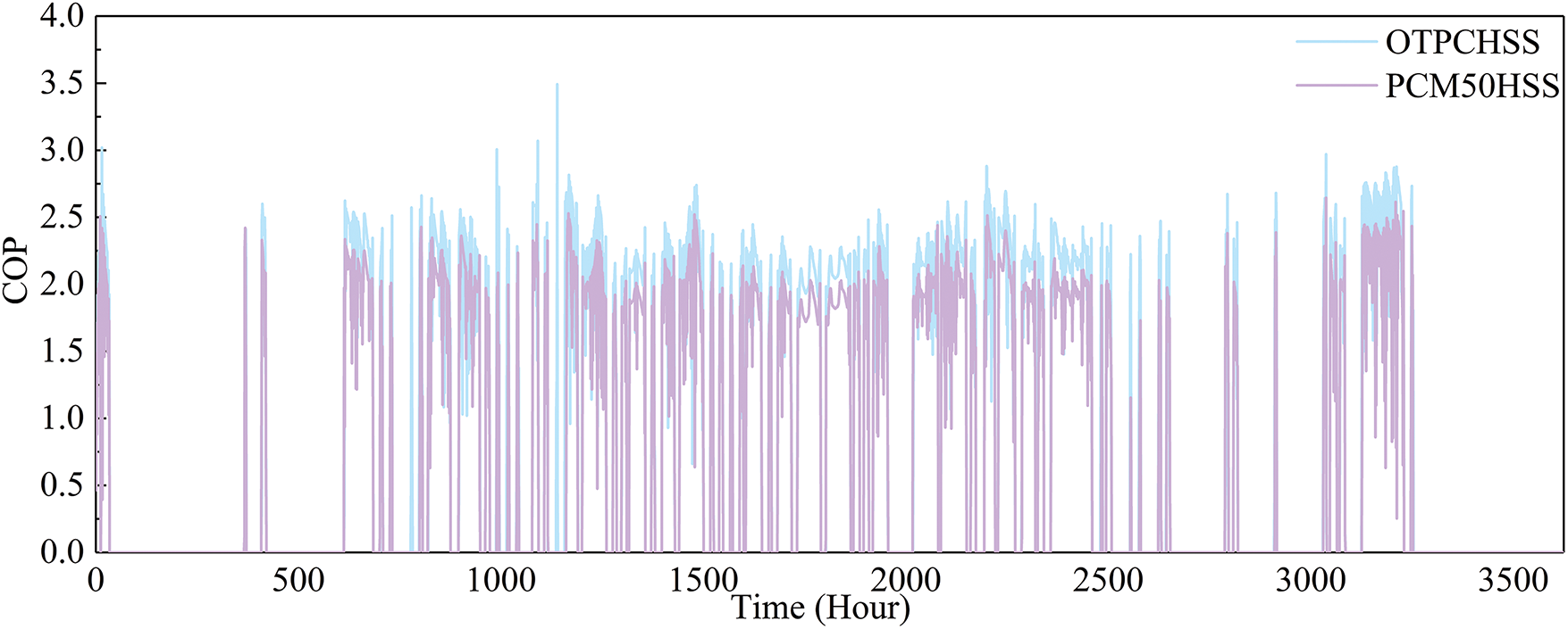
Figure 18: Air source heat pump COP data
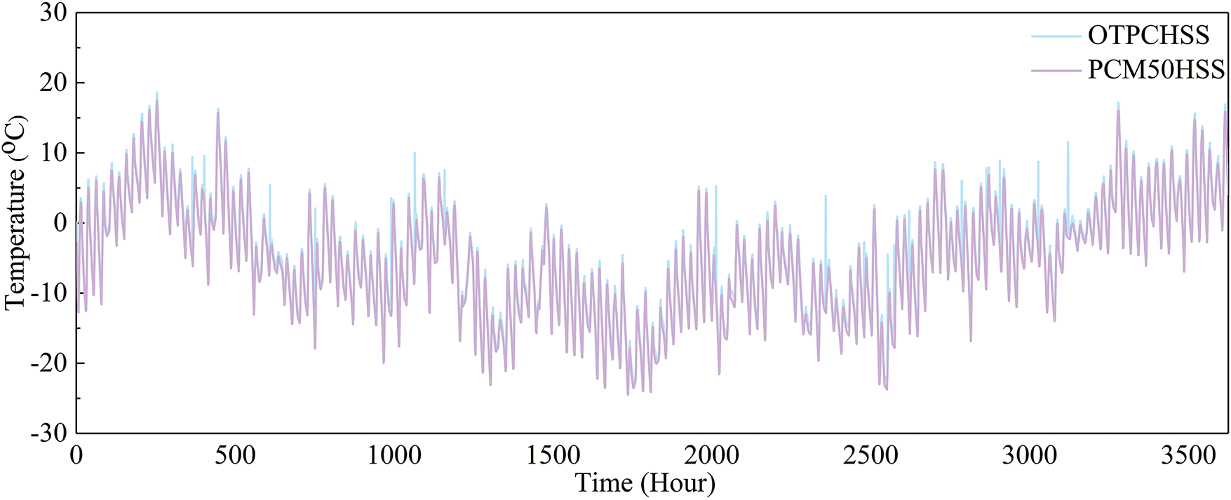
Figure 19: Comparison of inlet temperature of air source heat pump
The operational strategy of this study involves the overlapping operation of the air source heat pump and heat storage device. Although this operational strategy is effective, there is the possibility of redundancy or inefficient overlap between the two heating sources. Meanwhile, the operational strategy of this study does not involve the influence of fluctuating environmental conditions or unexpected load changes on the operation of heat storage devices. The future studies should be directed toward the overcoming of the above-mentioned limitations of this work. Therefore, the TPCHSS system still has something to be further studied.
This study investigates the operational performance of a solar coupled air source heat pump heating system integrated with two-stage phase change heat storage in severe cold regions. A system model was developed to analyze the impact of key parameters on system performance, followed by optimization of these parameters. The research highlights the benefits of utilizing staged phase change heat storage in cold climates, particularly for air source heat pump systems. The key findings are summarized as follows:
The thermal conversion efficiency of the PCM50 heat storage device is 80.2%, and that of the PCM30 heat storage device is 96.7%. Therefore, the TPCHSS system can store solar energy heat at different temperatures and effectively convert the stored heat.
The increase in solar energy collection area will reduce the energy consumption of the system, but it will increase the heating cost. Due to the limited of heat load required by buildings, the increase in air source heat pump power will increase the heating cost but the energy consumption of the system will not increase over time.
The parameters of the TPCHSS system are optimized based on the Hooke-Jeeves optimization method. The proportion of solar heating in the optimized TPCHSS system reaches 52.5%. The LCOH and CO2 emissions of the optimized TPCHSS system were reduced by 11.9% and 9.9%, respectively.
By comparing heating systems with different structures, it was found that preheating outdoor air with two-stage phase change heat storage devices in severe cold regions can improve COP of the air source heat pump and reduce system energy consumption. Therefore, the TPCHSS system realizes the graded utilization of solar energy heat and improves the utilization efficiency of solar energy.
In conclusion, the TPCHSS system represents an effective approach to integrating solar energy and phase change heat storage in severe cold regions, offering significant advantages in terms of energy efficiency, cost-effectiveness, and environmental sustainability. By optimizing system parameters and leveraging staged heat storage, the system maximizes solar energy utilization while minimizing reliance on auxiliary heating sources.
Acknowledgement: This work was supported by Cangzhou Jiaotong College School-Level Project in China.
Funding Statement: This work was supported by the project of the Research on Energy Consumption of Office Space in Colleges and Universities under the “Dual Carbon Target” (No. CJ202301006).
Author Contributions: Xueli Wang: Formal analysis and visualization. Yan Jia: Conceptualization, methodology, and writing—original draft. Degong Zuo: Investigation, writing—review and editing. All authors reviewed the results and approved the final version of the manuscript.
Availability of Data and Materials: Due to the nature of this research, participants of this study did not agree for their data to be shared publicly, so supporting data is not available.
Ethics Approval: Not applicable.
Conflicts of Interest: The authors declare no conflicts of interest to report regarding the present study.
References
1. Wei X, Shi X, Li Y, Ma H, Ban S, Liu X, et al. Analysis of the European energy crisis and its implications for the development of strategic energy storage in China. J Energy Storage. 2024;82(17):110522. doi:10.1016/j.est.2024.110522. [Google Scholar] [CrossRef]
2. Canelli R, Fontana G, Realfonzo R, Passarella M. Energy crisis, economic growth and public finance in Italy. Energy Econ. 2024;132(6):107430. doi:10.1016/j.eneco.2024.107430. [Google Scholar] [CrossRef]
3. Mughal N, Arif A, Jain V, Chupradit S, Shabbir M, Ramos-Meza C, et al. The role of technological innovation in environmental pollution, energy consumption and sustainable economic growth: evidence from South Asian economies. Energy Strategy Rev. 2022;39(5):100745. doi:10.1016/j.esr.2021.100745. [Google Scholar] [CrossRef]
4. Bp world energy statistics yearbook 2022. [Internet]. [cited 2025 Feb 24]. Available from: https://www.bp.com.cn/zh_cn/china/home.html. [Google Scholar]
5. Zhang R, Wang D, Liu Y, Chen Y, Fan J, Song C, et al. Economic optimization of auxiliary heat source for centralized solar district heating system in Tibetan plateau. China Energy Convers Manag. 2021;243(1):114385. doi:10.1016/j.enconman.2021.114385. [Google Scholar] [CrossRef]
6. Khan I, Chowdhury H, Rasjidin R, Alam F, Islam T, Islam S. Review of wind energy utilization in South Asia. Procedia Eng. 2012;49:213–20. doi:10.1016/j.proeng.2012.10.130. [Google Scholar] [CrossRef]
7. Zhang Z, Yu X, Li J, Wang L, Jin B, Niu G, et al. Explore the operational performance of phase change radiation terminal heating system in different heating zones of China. Front Energy Res. 2024;12:1504788. doi:10.3389/fenrg.2024.1504788. [Google Scholar] [CrossRef]
8. Wang L, Guo L, Ren J, Kong X. Using of heat thermal storage of PCM and solar energy for distributed clean building heating: a multi-level scale-up research. Appl Energy. 2022;321(1):119345. doi:10.1016/j.apenergy.2022.119345. [Google Scholar] [CrossRef]
9. Chen L, Yang H, Xiao Y, Tang P, Liu S, Chang M, et al. Exploring spatial pattern optimization path of urban building carbon emission based on low-carbon cities analytical framework: a case study of Xi’an, China. Sustain Cities Soc. 2024;111(19):105551. doi:10.1016/j.scs.2024.105551. [Google Scholar] [CrossRef]
10. Belfiori E, Rezai A. Implicit carbon prices: making do with the taxes we have. J Environ Econ Manag. 2024;125(5):102950. doi:10.1016/j.jeem.2024.102950. [Google Scholar] [CrossRef]
11. Ma X, Wang M, Lan J, Li C, Zou L. Influencing factors and paths of direct carbon emissions from the energy consumption of rural residents in central China determined using a questionnaire survey. Adv Clim Change Res. 2022;13(5):759–67. doi:10.1016/j.accre.2022.06.008. [Google Scholar] [CrossRef]
12. Chen C, Bi L. Study on spatio-temporal changes and driving factors of carbon emissions at the building operation stage—a case study of China. Build Environ. 2022;219:109147. doi:10.1016/j.buildenv.2022.109147. [Google Scholar] [CrossRef]
13. Teng J, Yin H, Wang P. Study on the operation strategies and carbon emission of heating systems in the context of building energy conservation. Energy Sci Eng. 2023;11(7):2421–30. doi:10.1002/ese3.1463. [Google Scholar] [CrossRef]
14. Sodiqjon K, Begyor S, Aleksandr K, Farrukh D, Mukhtasar M, Akbarjon A. Prospective aspects of using solar energy. J New Century Innov. 2022;18(1):142–8. [Google Scholar]
15. Pang Q, Xiang M, Zhang L, Chiu Y. Indirect carbon emissions from household consumption of middle-income groups: evidence from Yangtze river economic belt in China. Energy Sustain Dev. 2023;76:101280. doi:10.1016/j.esd.2023.101280. [Google Scholar] [CrossRef]
16. Karschin I, Geldermann J. Efficient cogeneration and district heating systems in bioenergy villages: an optimization approach. J Clean Prod. 2015;104:305–14. doi:10.1016/j.jclepro.2015.03.086. [Google Scholar] [CrossRef]
17. Zhang J, Li Y, Li L, Lu X, Zhang W, Kong X. An integrated system combining MDBHE (multi-casing DBHE) and heat pump achieves heating and cooling for medium-deep geothermal energy utilization. Energy. 2024;295(2):131061. doi:10.1016/j.energy.2024.131061. [Google Scholar] [CrossRef]
18. Bertsch SS, Groll E. Two-stage air-source heat pump for residential heating and cooling applications in northern US climates. Int J Refrig. 2008;31(7):1282–92. doi:10.1016/j.ijrefrig.2008.01.006. [Google Scholar] [CrossRef]
19. Zhang L, Jiang Y, Dong J, Yao Y. Advances in vapor compression air source heat pump system in cold regions: a review. Renew Sustain Energ Rev. 2018;81(5):353–65. doi:10.1016/j.rser.2017.08.009. [Google Scholar] [CrossRef]
20. Yin H, Yang Z, Chen A, Zhang N. Experimental research on a novel cold storage defrost method based on air bypass circulation and electric heater. Energy. 2012;37(1):623–31. doi:10.1016/j.energy.2011.10.040. [Google Scholar] [CrossRef]
21. Badar M, Zubair S, Al-Farayedhi A. Second-law-based thermoeconomic optimization of a sensible heat thermal energy storage system. Energy. 1993;18(6):641–9. doi:10.1016/0360-5442(93)90042-C. [Google Scholar] [CrossRef]
22. Zhao C, Lu W, Tian Y. Heat transfer enhancement for thermal energy storage using metal foams embedded within phase change materials (PCMs). Sol Energy. 2010;84(8):1402–12. doi:10.1016/j.solener.2010.04.022. [Google Scholar] [CrossRef]
23. Shao H, Nagel T, Roßkopf C, Linder M, Wörner A, Kolditz O. Non-equilibrium thermo-chemical heat storage in porous media: part 2—a 1D computational model for a calcium hydroxide reaction system. Energy. 2013;60(8):271–82. doi:10.1016/j.energy.2013.07.063. [Google Scholar] [CrossRef]
24. Sharma S, Sagara K. Latent heat storage materials and systems: a review. Int J Green Energy. 2025;2(1):1–56. doi:10.1081/GE-200051299. [Google Scholar] [CrossRef]
25. Jian Y, Falcoz Q, Neveu P, Bai F, Wang Y, Wang Z. Design and optimization of solid thermal energy storage modules for solar thermal power plant applications. Appl Energy. 2015;139:30–42. doi:10.1016/j.apenergy.2014.11.019. [Google Scholar] [CrossRef]
26. Farid M, Chen X. Domestic electrical space heating with heat storage. Proceedings of the institution of mechanical engineers: part A. J Power Energy. 1999;213(2):83–92. doi:10.1243/0957650991537455. [Google Scholar] [CrossRef]
27. Stoltze S, Mikkelsen J, Lorentzen B, Peterson PM, Qvale B. Waste-heat recovery in batch process using heat storage. J Energy Resour Technol. 1995;117(2):142–9. doi:10.1115/1.2835330. [Google Scholar] [CrossRef]
28. Tyagi V, Buddhi D. PCM thermal storage in buildings: a state of art. Renew Sustain Energ Rev. 2007;11(6):1146–66. doi:10.1016/j.rser.2005.10.002. [Google Scholar] [CrossRef]
29. Cao L, Krusius J, Korhonen M, Fisher T. Transient thermal management of portable electronics using heat storage and dynamic power dissipation control. IEEE Trans Compon Packag Manuf Technol: Part A. 1998;21(1):113–23. doi:10.1109/95.679040. [Google Scholar] [CrossRef]
30. Gao J, Li S, Adnouni M, Huang Y, Meng Y, Zhao Y, et al. Simulation study on thermal performance of solar coupled air source heat pump system with phase change heat storage in cold regions. Energy. 2024;308(3):132921. doi:10.1016/j.energy.2024.132921. [Google Scholar] [CrossRef]
31. Gao J, Li S, Wu F, Jiang L, Zhao Y, Zhang X. Study on efficient heating method by solar coupled air source heat pump system with phase change heat storage in severe cold region. Appl Energy. 2024;367(7):123206. doi:10.1016/j.apenergy.2024.123206. [Google Scholar] [CrossRef]
32. Tomar V, Tsang E, Li D. Performance analysis of a prototype solar photovoltaic/wickless heat pipe embedded aluminum curtain wall-heat pump water heating system. Energy Convers Manag. 2022;258(3):115559. doi:10.1016/j.enconman.2022.115559. [Google Scholar] [CrossRef]
33. Shabgard H, Robak C, Bergman T, Faghri A. Heat transfer and exergy analysis of cascaded latent heat storage with gravity-assisted heat pipes for concentrating solar power applications. Sol Energy. 2012;86(3):816–30. doi:10.1016/j.solener.2011.12.008. [Google Scholar] [CrossRef]
34. Han J, Zhang C, Wang L, Chang Z, Zhao Q, Shi Y, et al. Research on operation optimization of heating system based on electric storage coupled solar energy and air source heat pump. Energy Eng J Assoc Energy Eng. 2023;120(9):1991–2011. doi:10.32604/ee.2023.029749. [Google Scholar] [CrossRef]
35. Wang L, Yuan J, Qiao X, Kong X. Optimal rule based double predictive control for the management of thermal energy in a distributed clean heating system. Renew Energy. 2023;215(205):118924. doi:10.1016/j.renene.2023.118924. [Google Scholar] [CrossRef]
36. Kicsiny R, Farkas I. Improved differential control for solar heating systems. Sol Energy. 2012;86(11):3489–98. doi:10.1016/j.solener.2012.08.003. [Google Scholar] [CrossRef]
37. Fu S, Wang L, Long H. Research on the optimization of the clean heating system for regional residential buildings based on the multi-objective optimization strategy. Front Energy Res. 2024;12:1374369. doi:10.3389/fenrg.2024.1374369. [Google Scholar] [CrossRef]
38. Liu H, Tana, Zhen Q, Hurichabilige, Meng X, Li W. Environ-economic assessment of the solar coupled heat pump heating system for dairy barns in severe cold region. Energy Build. 2025;328(21):115166. doi:10.1016/j.enbuild.2024.115166. [Google Scholar] [CrossRef]
39. Nienborg B, Gschwander S, Munz G, Fröhlich D, Helling T, Horn R, et al. Life cycle assessment of thermal energy storage materials and components. Energy Proc. 2018;155:111–20. doi:10.1016/j.egypro.2018.11.063. [Google Scholar] [CrossRef]
40. Mahmud M, Huda N, Farjana S, Lang C. Environmental impacts of solar-photovoltaic and solar-thermal systems with life-cycle assessment. Energies. 2018;11(9):2346. doi:10.3390/en11092346. [Google Scholar] [CrossRef]
41. Li H, Li J, Kong X, Long H, Yang H, Yao C. A novel solar thermal system combining with active phase-change material heat storage wall (STS-APHSWdynamic model, validation and thermal performance. Energy. 2020;201(8–9):117610. doi:10.1016/j.energy.2020.117610. [Google Scholar] [CrossRef]
Cite This Article
 Copyright © 2025 The Author(s). Published by Tech Science Press.
This work is licensed under a Creative Commons Attribution 4.0 International License , which permits unrestricted use, distribution, and reproduction in any medium, provided the original work is properly cited.
 Downloads
 Citation Tools