
 Submit a Paper
 Propose a Special lssue
 Open Access
ARTICLE

Online Optimization to Suppress the Grid-Injected Power Deviation of Wind Farms with Battery-Hydrogen Hybrid Energy Storage Systems
1 State Grid Zhejiang Electric Power Co., Ltd., Electric Power Research Institute, Hangzhou, 310014, China
2 Key Laboratory of Modern Power System Simulation Control and Green Power New Technology of the Ministry of Education, Northeast Electric Power University, Jilin, 132012, China
* Corresponding Author: Xingxu Zhu. Email:
Energy Engineering 2025, 122(4), 1403-1424. https://doi.org/10.32604/ee.2025.060256
Received 28 October 2024; Accepted 24 December 2024; Issue published 31 March 2025
 View Full Text
 Download PDF
Abstract
To address the issue of coordinated control of multiple hydrogen and battery storage units to suppress the grid-injected power deviation of wind farms, an online optimization strategy for Battery-hydrogen hybrid energy storage systems based on measurement feedback is proposed. First, considering the high charge/discharge losses of hydrogen storage and the low energy density of battery storage, an operational optimization objective is established to enable adaptive energy adjustment in the Battery-hydrogen hybrid energy storage system. Next, an online optimization model minimizing the operational cost of the hybrid system is constructed to suppress grid-injected power deviations with satisfying the operational constraints of hydrogen storage and batteries. Finally, utilizing the online measurement of the energy states of hydrogen storage and batteries, an online optimization strategy based on measurement feedback is designed. Case study results show: before and after smoothing the fluctuations in wind power, the time when the power exceeded the upper and lower limits of the grid-injected power accounted for 24.1% and 1.45% of the total time, respectively, the proposed strategy can effectively keep the grid-injected power deviations of wind farms within the allowable range. Hydrogen storage and batteries respectively undertake long-term and short-term charge/discharge tasks, effectively reducing charge/discharge losses of the Battery-hydrogen hybrid energy storage systems and improving its operational efficiency.Keywords
The development and utilization of wind power and other renewable energy sources are essential for achieving the low-carbon goals. However, due to natural factors such as wind speed, wind power generation exhibits uncertainty and intermittency [1], which poses a significant threat to the safe operation of the power system when large proportions of wind power are connected to the grid, thus limiting the large-scale development and utilization of wind energy. Hydrogen energy storage and battery energy storage can achieve time-shifting of electrical energy and have fast response times [2], effectively mitigating wind power fluctuations in grid connections. This makes them an effective solution for ensuring the safe operation of large-scale wind power integration. A hybrid energy storage system, composed of battery and hydrogen energy storage, can complement the strengths and weaknesses of different types of storage, addressing the shortcomings of single-type energy storage [3] and improving the overall performance of the energy storage system [4]. It is crucial to design effective control strategies for such multi-type energy storage systems.
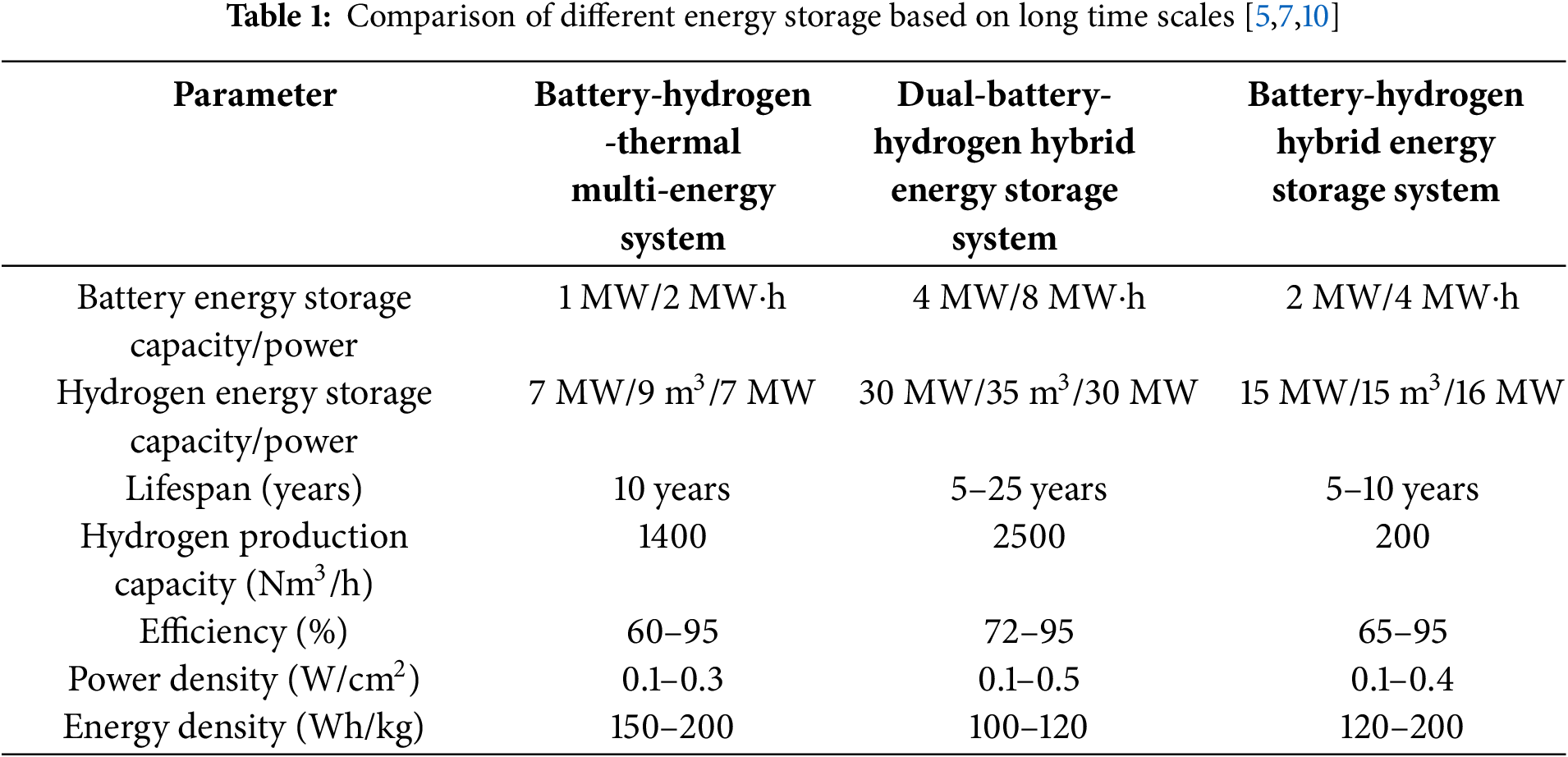
At present, a lot of research results have been made in the research on long-term energy storage to solve the problem of supply and demand imbalance. In reference [5], an hourly-level coordinated optimization strategy for a Battery-hydrogen integrated system, including hydrogen fuel vehicles, was proposed. Reference [6] presented an improved bi-level robust planning approach to smooth the fluctuations of renewable energy generation, maximizing the complementary benefits of Battery-hydrogen energy storage. Reference [7] proposed a dual-battery energy storage model and compared two switching strategies, synchronous and asynchronous, to reduce the switching frequency in a single-battery mode. Reference [8] proposed a multi-time-scale rolling optimization control method based on the rolling optimization idea of model predictive control to address the low reliability of optimization results due to uncertainties in wind and solar output and load. Reference [9] presented an energy storage response strategy aiming to minimize the cost of a hybrid energy storage system, based on the multi-time-scale demand of users. Reference [10] proposed a peak-shaving and valley-filling strategy for a park energy system with a Battery-thermal hybrid energy storage system. Reference [11], in light of the escalating penetration of renewable energy to counterbalance the variability of wind and solar energy and the demand issue for compressed air energy storage capacity, has formulated a least-cost power system founded on the combination of wind, solar, and compressed air energy storage technologies. Reference [12], for the research concerning the utilization of a substantial amount of energy storage to mitigate the variability of wind and solar power systems, has put forward a novel least-cost approach. Through the comparative analysis of the above literature, the comparison results are shown in Table 1.
The above studies discuss the operation optimization strategies of long-term energy storage systems, however, most of their time levels are above the hour, which is difficult to cope with the control tasks of shorter time scales. In response, reference [13] proposed a second-level coordinated operation method for a Battery-hydrogen hybrid energy storage systems that can optimize the state of charge and improve renewable energy utilization while reducing system operational costs. Reference [14] proposed a hybrid energy storage coordination strategy to smooth photovoltaic grid-injected power fluctuations and reduce operational losses in the hybrid energy storage system. Reference [15] presented a fast control strategy to reduce the frequency of charge/discharge cycles in battery energy storage. Reference [16] presented A two-layer optimization model of hydrogen energy storage in an integrated energy system considering the load-side demand response and the user group of electric heating equipment is proposed, which can improve the level of new energy consumption. Reference [17] proposed an optimal scheduling model for integrated energy microgrids considering multi-time scale energy storage. Reference [18] established a multi-objective operational model for a Battery -hydrogen hybrid energy storage microgrid, which can improve the utilization of clean energy and reduce microgrid operating costs and user electricity expenses. Reference [19] proposed a predictive control strategy for a micro wind-hydrogen coupled system, significantly enhancing the regulation capabilities of the hydrogen energy storage system. Reference [20] proposed a control strategy for a Battery-hydrogen hybrid energy storage systems, considering the operational characteristics of alkaline electrolyzers. Reference [21] introduced a multi-type energy storage frequency control strategy with adaptive time constant adjustment. The aforementioned short-time-scale (minute-level, second-level) control strategies for Battery-hydrogen hybrid energy storage systems facilitate rapid power distribution. Nevertheless, the majority rely on filtering or heuristic distribution strategies [22], which restrict their applicability to specific control objectives and scenarios.
To address this, this paper proposes an online optimization strategy for a Battery-hydrogen hybrid energy storage systems based on measurement feedback. This strategy can quickly optimize the distribution of charge/discharge power among multiple battery and hydrogen storage units while suppressing wind power grid-injected deviations. An online optimization model for adaptive energy adjustment in the Battery-hydrogen hybrid energy storage systems is constructed, considering the need to suppress wind power grid-injected deviations and the physical operating characteristics of battery and hydrogen storage. By utilizing the real-time measurement of energy states in hydrogen and battery storage units, an online optimization strategy based on measurement feedback is designed. Simulation results demonstrate that the proposed strategy can effectively suppress wind power grid-injected deviations within permissible limits. Hydrogen and battery storage undertake long-term and short-term charge/discharge tasks, respectively, reducing overall energy storage system charge/discharge losses and enhancing its operational efficiency.
Overall, the main contribution of this paper is three-fold:
(1) We have developed an online optimization model for the energy self-adaptive adjustment of a Battery-hydrogen hybrid energy storage system. The model uses hydrogen storage to smooth out long-term wind power fluctuations and battery storage to mitigate short-term wind power fluctuations.
(2) Compared with heuristic algorithms, the strategy proposed in this paper can quickly allocate power among multiple hydrogen storage and battery units with greater precision regarding optimization objectives and constraints.
(3) Simulation results demonstrate that the proposed strategy can effectively suppress wind power grid-injected deviations within permissible limits. Hydrogen and battery storage undertake long-term and short-term charge/discharge tasks, respectively, reducing overall energy storage system charge/discharge losses and enhancing its operational efficiency.
The structure of this paper is organized as follows: The first section introduces the operational and control architecture of the Battery-hydrogen hybrid energy storage system. The second section discusses the model of the Battery-hydrogen hybrid energy storage system in detail, considering the need to suppress wind power grid-injected deviations and the physical operating characteristics of battery and hydrogen storage. By utilizing the real-time measurement of energy states in hydrogen and battery storage units, an online optimization strategy based on measurement feedback is designed. The third section conducts an analysis based on practical case studies by setting parameters for the wind farm energy storage station, analyzing the power and State of Health (SOH) of multiple hydrogen storage units, as well as the power and State of Charge (SOC) of the energy storage units. Finally, the fourth section summarizes the main research findings of this paper and outlines future research directions. The appendix includes the main proof processes and formula derivations.
2 Battery-Hydrogen Hybrid Energy Storage Operation Control Architecture
2.1 Battery-Hydrogen Hybrid Energy Storage Systems Framework
The research in this paper focuses on the Battery-hydrogen hybrid energy storage systems and the wind power system. The system structure is shown in Fig. 1.
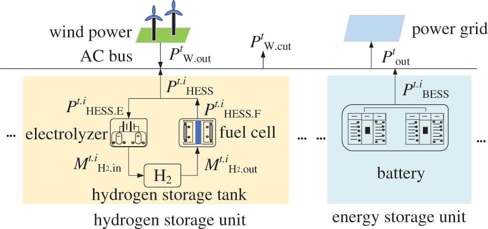
Figure 1: Schematic diagram of the Battery-hydrogen hybrid energy storage system
The expression as shown in Eq. (1) can be obtained from the relationship in the figure:
2.2 Control Mechanism of Energy Storage System for Suppressing the Grid-Injected Power Deviation of Wind Farms
A schematic diagram illustrating the actual wind power and its upper and lower limits of the grid-injected power is shown in Fig. 2.
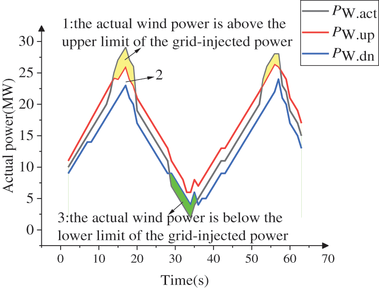
Figure 2: Actual wind power operation diagram
The black curve in the figure represents the actual wind power, while the red and blue curves represent the upper and lower limits of the grid-injected power, respectively. Based on the relationships in the figure, we can derive:
Based on the relationship between actual wind power and the upper and lower limits of the grid-injected power, it can be divided into the following three regions. The yellow shaded area 1 indicates that the actual wind power is above the upper limit of the grid-injected power; in this case, the Battery-hydrogen hybrid energy storage systems need to charge. If the power adjusted by the Battery-hydrogen hybrid energy storage systems remains above the upper limit of the grid-injected power, wind power curtailment will occur. The blank area 2 indicates that the actual wind power is within the upper and lower limits of the grid-injected power. In this area, the output of the Battery-hydrogen hybrid energy storage systems aims to restore the SOC and SOH. Through reasonable charge and discharge control, the energy storage system can ensure efficient operation and maintain its good condition. The green shaded area 3 indicates that the actual wind power is below the lower limit of the grid-injected power; in this case, the Battery-hydrogen hybrid energy storage systems need to discharge to supplement the insufficient Battery-hydrogen hybrid energy storage systems power. As shown in Eq. (3), ideally, the adjusted wind power should remain within the upper and lower limits of the grid-injected power.
3 Model of the Battery-Hydrogen Hybrid Energy Storage Systems
Considering the disadvantages of high charge and discharge losses in battery and hydrogen storage and low energy density in battery storage, the aim is to quickly restore the SOC of the battery energy storage while minimizing the charge and discharge of battery and hydrogen storage. To this end, the operational objective function of the Battery-hydrogen hybrid energy storage systems is designed as follows:
The penalty function of the state of charge of batteries and hydrogen storage are shown in Eqs. (6) and (7), respectively. The function curves are illustrated in Fig. 3.
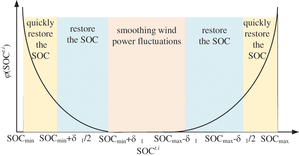
Figure 3: Relationship between φ(SOCt.i) and SOCt.i
In Eqs. (6) and (7), δ1 and δ2 are the parameters of battery energy storage and hydrogen energy storage, respectively, which determine the size of the piecewise function interval, the larger the δ1/δ2 value, the more effortless it is to restore the SOC/SOH state, and the smaller the δ1/δ2 value, the more challenging it is to restore the SOC/SOH state. By adjusting the relevant parameters in the penalty functions φ(SOCt.i) and φ(SOHt.i), the charge and discharge processes of the two types of energy storage can be altered. The smaller the SOCmax/SOCmin and the larger the SOHmax/SOHmin, the easier it is to restore the SOC and SOH states; conversely, larger values make it harder to restore the SOC and SOH states. In practice, the appropriate parameter values can be chosen based on the control requirements of hydrogen storage and battery storage.
Additionally, the penalty functions φ(SOCt.i) and φ(SOHt.i) are second-order continuous. On one hand, this helps to suppress drastic changes when the related variables approach their constraints (such as the upper/lower limits for SOC or SOH). On the other hand, it ensures that the optimization problem constructed using the penalty functions is also second-order continuous, which is typically one of the assumptions required for proving the convergence of online optimization algorithms.
By taking the partial derivatives of the penalty functions for battery energy storage SOC and hydrogen energy storage SOH, we can obtain the expressions (A1) and (A2) in Appendix A.
3.2.1 Operational Constraints of Battery Energy Storage
The SOC of the battery energy storage system is an important indicator of its current energy level and is closely related to its energy and capacity. The changes in the state of charge reflect the energy status of the storage system at different time points [23], ensuring stability and efficiency during operation. The specific expression is shown in Eq. (8).
To ensure the quality of electrical energy, the charge and discharge power of the battery energy storage system must be maintained within a reasonable range to prevent damage to the storage system [24] or to avoid affecting its performance, as shown in Eq. (10).
3.2.2 Hydrogen Energy Storage Operational Constraints
(1) Electrolyzer operational constraints
The key equipment for hydrogen energy storage is the alkaline electrolyzer, which converts electrical energy into hydrogen energy. The specific expression is shown in Eq. (11).
From the inequality constraints in Eq. (12) and the relational expression in Eq. (11), the power constraints at this time can be derived.
The electrolyzer is subject to the constraints from both Eqs. (12) and (13). The smaller value from these two constraints is taken as the upper limit for the input power of the electrolyzer, thereby obtaining the input power constraint of the electrolyzer, as shown in Eq. (14).
(2) Hydrogen Storage Tank Operational Constraints
The primary function of the hydrogen storage tank is to effectively store the hydrogen produced by the electrolyzer and supply it to the fuel cell when needed. Through the regulation of the hydrogen storage tank, the system can respond flexibly to fluctuations in power demand, enhancing the overall reliability and efficiency of the energy system.
To ensure the service life of the hydrogen storage tank, the amount of hydrogen input and output per unit of time must be kept within a reasonable range. This not only helps to extend the lifespan of the storage tank but also ensures the safe and efficient operation of the system, enhancing the reliability of the entire hydrogen energy storage system [25].
(3) Fuel Cell Operational Constraints
The fuel cell is a highly efficient device that converts the hydrogen energy provided by the hydrogen storage tank into electrical energy [26]. The hydrogen stored in the tank is transported to the fuel cell via pipelines, providing a stable power output while also reducing environmental pollution [27].
From the inequality constraints in Eq. (18) and the relational expression in Eq. (17), the power constraints at this time can be derived.
The fuel cell is subject to the constraints from both Eqs. (18) and (19). The smaller value from these two constraints is taken as the upper limit for the fuel cell’s output power, thereby obtaining the output power constraint of the fuel cell, as shown in Eq. (20).
3.3 Control Strategy Based on Measurement Feedback
3.3.1 Measurement Feedback-Based Energy Storage Online Optimization Principle
In order to deal with such a complex optimization problem as Eq. (3), this paper constructs a Lagrangian function to transform the constrained optimization problem into an unconstrained optimization problem.
Thus, during regulation, the active output power of hydrogen energy storage and battery energy storage is updated based on Eqs. (22) and (23), respectively.
Taking
By substituting Eqs. (A1) and (A2) into Eq. (24), the gradient of the Lagrangian function can be obtained as shown in Eq. (A3) in Appendix A. Similarly, by taking the partial derivative of the Lagrangian function with respect to the hydrogen energy storage power, the gradient can be derived as shown in Eq. (A4) in Appendix A.
According to Eqs. (22) and (23), the initially allocated power for the Battery-hydrogen hybrid energy storage systems can be obtained. Then, using Eq. (1), the adjusted wind power can be calculated. If the adjusted wind power is not within the upper and lower limit range of the grid-injected power, the strategy presented in this paper is needed to adjust the upper and lower Lagrange multiplier for exceeding the wind power upper limit, namely:
3.3.2 Online Optimization Strategy Flow for Battery-Hydrogen Hybrid Energy Storage Systems
The online optimization strategy flow for the Battery-hydrogen hybrid energy storage systems based on measurement feedback is shown in Fig. 4. Measurable equipment continuously monitors the power of the hydrogen storage unit and energy storage unit. Based on Eqs. (4), (6), and (7), the gradients of the operating cost objective function, state of charge penalty function, and hydrogen state penalty function are calculated. These gradients are then substituted into Eq. (24) to compute the gradient of the Lagrangian function. This gradient is subsequently used in Eqs. (22) and (23) to calculate the hydrogen energy storage and battery energy storage power for the next time step. Finally, Eq. (25) is utilized to adjust the energy output for the next time step.
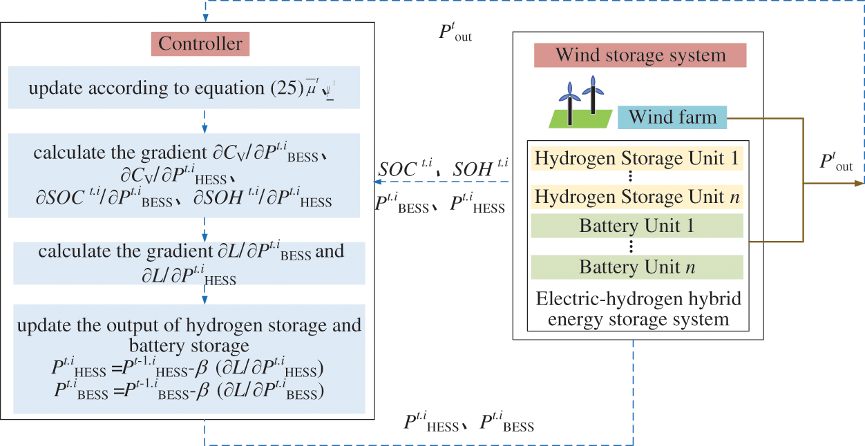
Figure 4: Online optimization diagram of electric-hydrogen hybrid energy storage system
3.3.3 Online Optimization Strategy Analysis
Based on the different intervals of SOC and SOH (in Eqs. (6) and (7), SOCmin/SOHmin to SOCmin + δ1/2/SOHmin + δ2/2 is defined as the first interval, SOCmin + δ1/2/SOHmin + δ2/2 to SOCmin + δ1/SOHmin + δ2 is defined as the second interval, SOCmin + δ1/SOHmin + δ2 to SOCmax − δ1/SOHmax − δ2 is defined as the third interval, SOCmax − δ1/SOHmax − δ2 to SOCmax − δ1/2/SOHmax − δ2/2 is defined as the fourth interval, SOCmax − δ1/2/SOHmax − δ2/2 to SOCmax − δ1/SOHmax − δ2 is defined as the fifth interval), as well as the relationship between PtW.act and PtW.dn, the energy storage allocation under the control strategy presented in this paper can be determined:
(1) When SOC is in the first and second intervals
a) When SOH is in the first and second intervals, and PtW.act > PtW.dn, energy storage charging is required. If the battery energy storage power exceeds its maximum power, then Pt.iBESS.E = PBESS.E.max. If the hydrogen energy storage power exceeds its maximum power, then, as shown in Eq. (26).
When PtW.act < PtW.dn, energy storage discharging is required. Due to the significant losses associated with the frequent start-stop of the electrolyzer, which also greatly impacts its lifespan, the electrolyzer operates at standby power: Pt.iBESS.E = Pelec.min.
b) When SOH is in the third, fourth, or fifth intervals, and PtW.act > PtW.dn, energy storage charging is required. At this time, SOC is at a relatively low state while SOH is at a higher state, so battery energy storage is prioritized for charging. When PtW.act < PtW.dn, energy storage discharging is needed; since SOC is lower than SOH, hydrogen energy storage is prioritized for discharging.
(2) When SOC is in the third interval
a) When SOH is in the first or second interval, and PtW.act > PtW.dn, energy storage charging is required. At this time, SOC is at a higher state while SOH is at a lower state, so hydrogen energy storage is prioritized for charging. When PtW.act < PtW.dn, energy storage discharging is needed; since SOC is higher than SOH, battery energy storage is prioritized for discharging.
b) When SOH is in the third, fourth, or fifth interval, and PtW.act > PtW.dn, energy storage charging is required. At this time, SOC is at a lower state while SOH is at a higher state, so battery energy storage is prioritized for charging. When PtW.act < PtW.dn, energy storage discharging is needed; since SOC is lower than SOH, hydrogen energy storage is prioritized for discharging.
(3) When SOC is in the fourth or fifth interval
a) When SOH is in the first, second, or third interval, and PtW.act > PtW.dn, energy storage charging is required. At this time, SOC is at a higher state while SOH is at a lower state, so hydrogen energy storage is prioritized for charging. When PtW.act < PtW.dn, energy storage discharging is needed; since SOC is higher than SOH, battery energy storage is prioritized for discharging.
b) When SOH is in the fourth or fifth interval, and PtW.act > PtW.dn, energy storage charging is required. At this time, SOC is at a higher state while SOH is at a lower state, so hydrogen energy storage is prioritized for charging. If the electrolyzer is operating at minimum power such that SOHt.i ≤ SOHmax, charging can continue. However, if the electrolyzer is operating at minimum power and SOHt.i > SOHmax, to ensure the safety of the hydrogen energy storage tank, the fuel cell must discharge. When PtW.act < PtW.dn, energy storage discharging is required; since SOC is higher than SOH, battery energy storage is prioritized for discharging. If the battery energy storage power exceeds its maximum power, then Pt.iBESS.F = PBESS.F.max. If the hydrogen energy storage power exceeds its maximum power, then, as shown in Eq. (27).
4 Case Study and Simulation Analysis
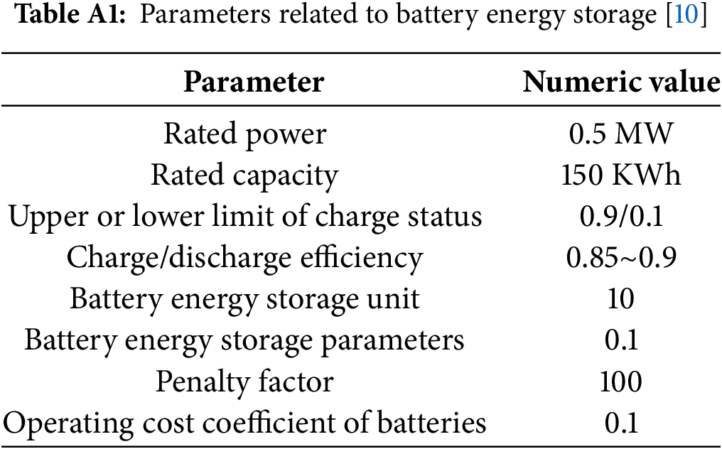
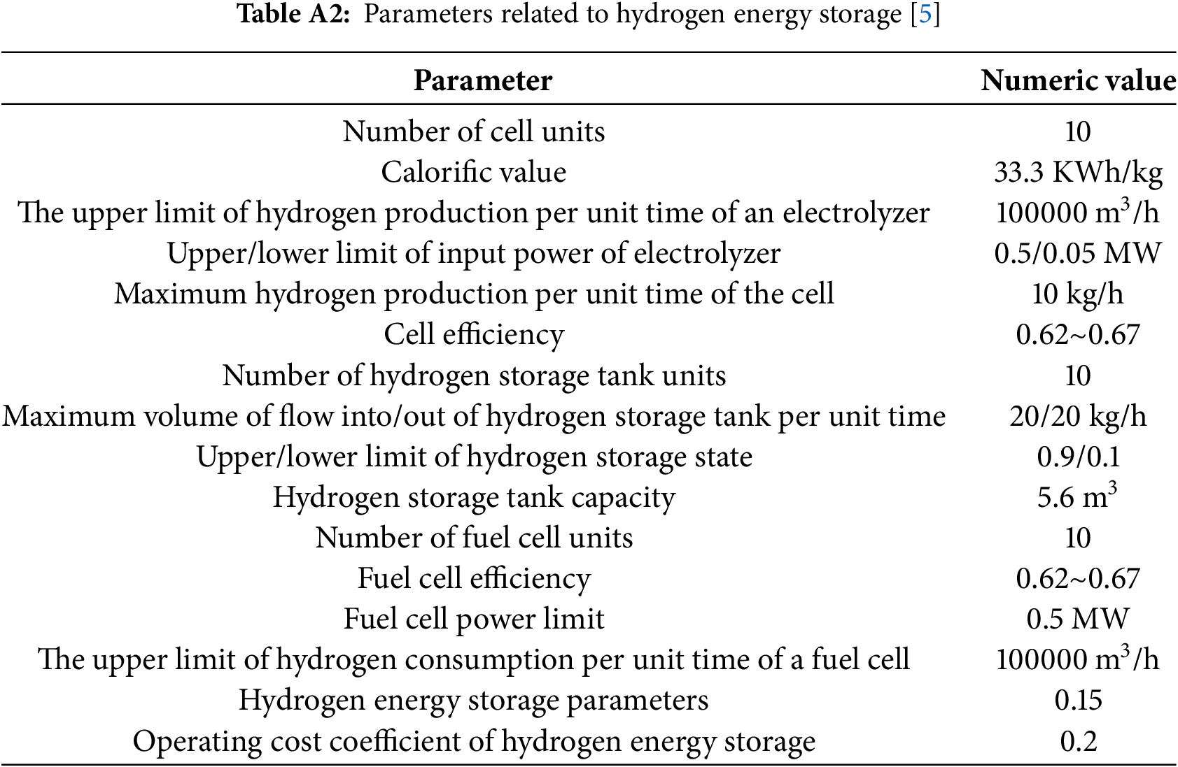
To verify the effectiveness of the strategy proposed in this paper, actual wind power data from a city in northeastern China in 2023 was used. The region has a wind farm with an installed capacity of 200 MW, equipped with 15 MW of battery energy storage capacity and 20 MW of hydrogen energy storage capacity. Other specific parameters for battery and hydrogen energy storage can be found in Tables A1 and A2. The sampling period is set to 7 days, with a sampling interval of 1 s. The simulation tool uses MATLAB.
4.2 Simulation Analysis of Wind Power Smoothing
Fig. 5a,c shows the relationship between wind power before and after smoothing and its upper and lower limits of the grid-injected power. It was found that, before smoothing, the wind power exceeded the upper limit of the grid-injected power between 740 and 800 s and dropped below the lower limit of the grid-injected power between 3200 and 3400 s. After smoothing, the wind power remained within the upper and lower limit of the grid-injected power during these intervals. In Fig. 5b,d, the blue curve represents the portion of the wind power that exceeds its upper limit of the grid-injected power, and the red curve represents the portion that falls below its lower limit of the grid-injected power. After adjustments based on the proposed strategy, the power exceeding the upper and lower limits of the grid-injected power was reduced to around 0.1 MW, the time during which the power exceeded the upper and lower limits of the grid-injected power accounted for 1.45% of the total time; whereas before the adjustment, the power exceeded the upper and lower limits of the grid-injected power by about 3 MW, the time during which the power exceeded the upper and lower limits of the grid-injected power accounted for 24.1% of the total time. This shows that the wind power curve became more stable after regulation, with significantly reduced fluctuations. This indicates that the proposed control strategy can effectively reduce the volatility of wind power, making it more controllable, and better meeting the power system’s requirements for wind power output.
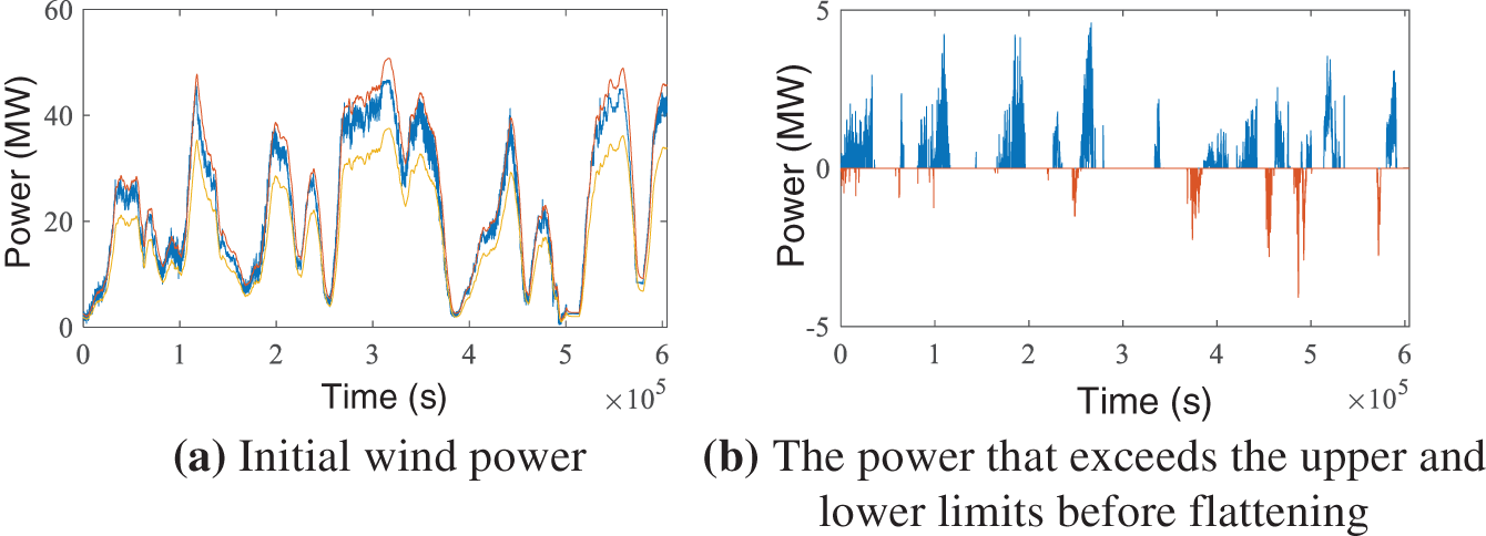
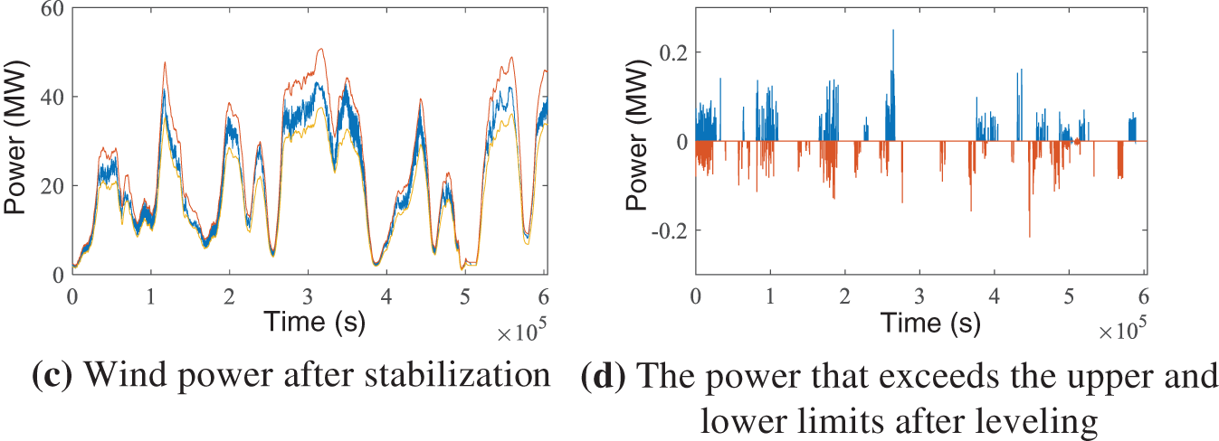
Figure 5: Comparison of wind power before and after stabilization
4.3 Simulation Analysis of Energy Storage Unit Power with SOC and Hydrogen Storage Unit Power with SOH
Fig. 6 shows the power distribution within the energy storage unit, where all power fluctuates within the range of −0.5 to 0.5 MW, without exceeding this range. This indicates that the proposed power distribution strategy for the energy storage unit is highly effective.
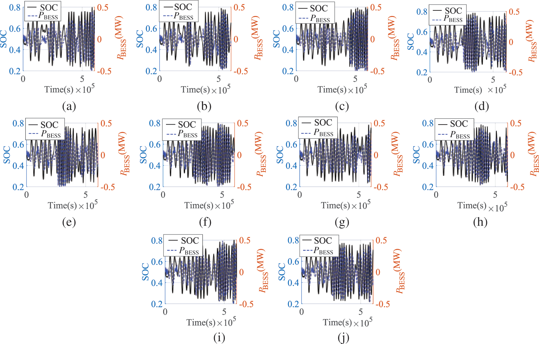
Figure 6: Diagram of SOC and power variation of 10 cells
Due to differences in internal power distribution and the introduction of penalty functions, the SOC of each battery varies, but the overall trend remains consistent. Each battery’s SOC changes smoothly within the range of 0.3 to 0.7, with the curve becoming more stable. In the 0.2 to 0.3 and 0.7 to 0.8 ranges, the SOC curve changes more rapidly, and in the 0.1 to 0.2 and 0.8 to 0.9 ranges, the SOC curve changes significantly faster. Through rapid adjustment of power distribution, the system can effectively bring SOC back to a more optimal range, thereby avoiding the risks of overcharging or overdischarging. These results demonstrate that the proposed strategy can effectively manage the SOC of the energy storage unit under various operating conditions, ensuring both the safety and efficiency of the system.
Fig. 6 shows that the SOC can be maintained within a reasonable range under different cell efficiency, and compared with hydrogen energy storage, battery energy storage can be charged and discharged more frequently, fully exerting its high efficiency, thereby verifying the efficacy of the adaptive adjustment of the operation optimization objective function in this paper.
Fig. 7 shows the power distribution within the hydrogen storage unit, where all power fluctuates within the range of −0.5 to 0.5 MW, without exceeding this range.
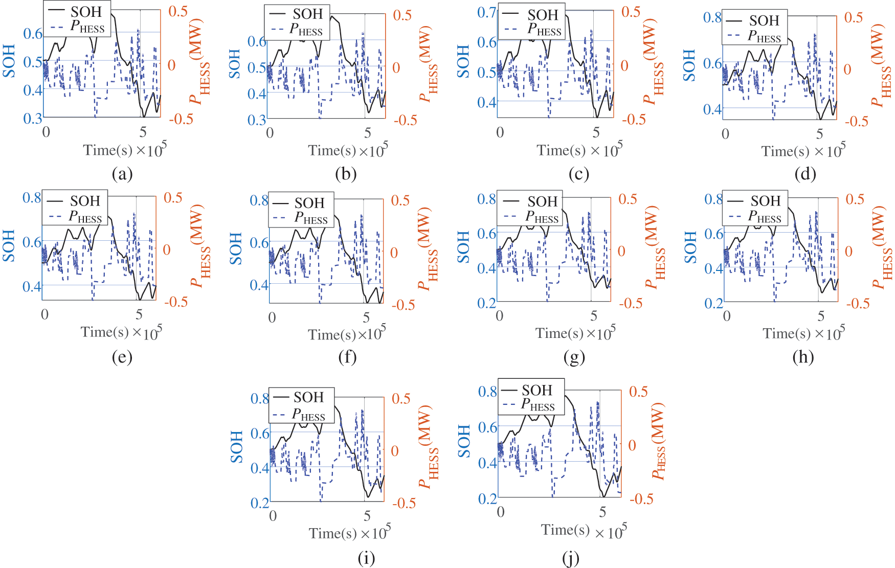
Figure 7: Diagram of SOH vs. power variation of ten hydrogen storage units
Due to differences in internal power distribution and the introduction of penalty functions, the SOH of each hydrogen storage unit varies, but the trend of SOH changes across different intervals is similar to that of SOC. Considering the higher loss associated with hydrogen energy storage during charging and discharging, as well as the lower energy density of battery energy storage, the penalty function for hydrogen storage is set to be larger than that for battery storage. As a result, the SOC tends to change more frequently, while SOH changes more gradually.
Overall, by comparing the SOC and SOH curves of battery and hydrogen energy storage, the dynamic response characteristics of different energy storage systems under the corresponding control strategy are evident. Hydrogen and battery storage are respectively responsible for long-term and short-term charging and discharging tasks, reducing the losses of hydrogen energy storage and keeping the battery SOC within the allowable range.
To further study the distribution and variation of power in more detail, we performed a magnified analysis of a specific time interval. As shown in Fig. 8, the time period between 740 and 800 s was selected to magnify the situation where the wind power exceeds the upper limit of the grid-injected power. When the actual wind power exceeds its upper limit of the grid-injected power, according to the strategy proposed in this paper, the upper lagrange multiplier for exceeding the wind power upper limit is adjusted to increase the gradient. As the gradient increases, the power at the next moment tends to move towards negative values (in this paper, negative values indicate charging, while positive values indicate discharging). Therefore, the increase in the gradient will cause the system to tend toward more charging operations at the next moment.
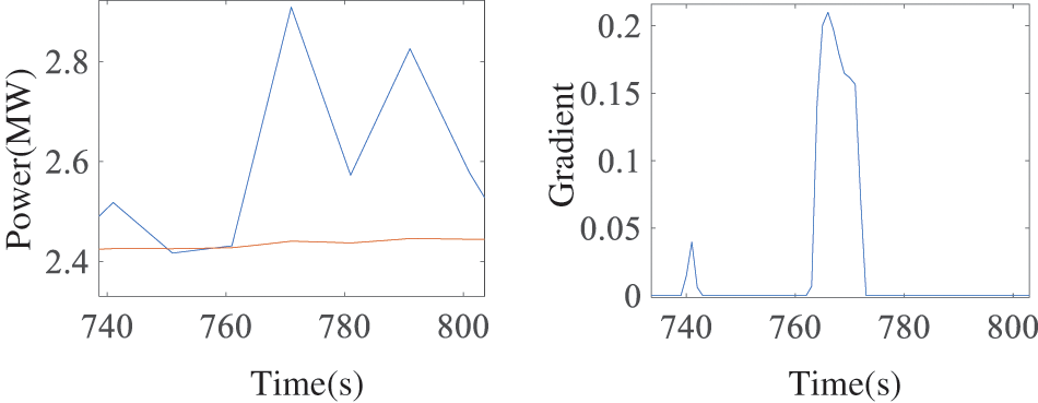
Figure 8: Enlarged plots and their gradients that exceed the upper limit
As shown in Fig. 9, the charging power of both battery energy storage and hydrogen energy storage increases as the gradient increases. When the energy storage system charges, it can effectively reduce the power adjusted by the energy storage system.
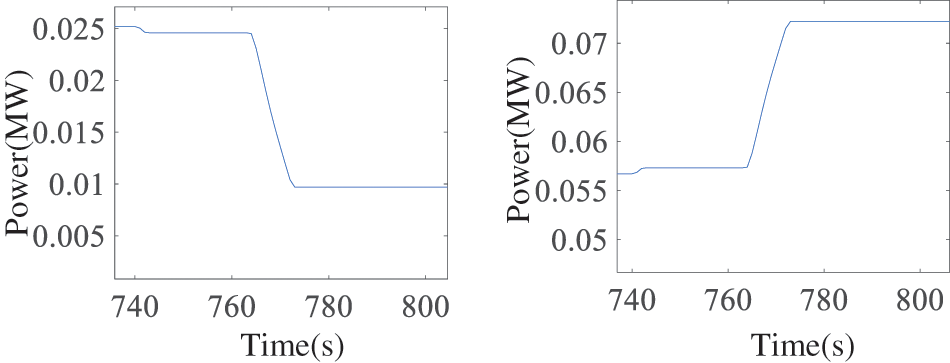
Figure 9: Battery energy storage and hydrogen energy storage charging power
As shown in Fig. 10, the time period between 3200 and 3400 s was selected to magnify the situation where the wind power falls below the lower limit of the grid-injected power. When the actual wind power is lower than its lower limit of the grid-injected power, according to the strategy proposed in this paper, the lower lagrange multiplier for exceeding the wind power lower limit should be adjusted to reduce the gradient. The decrease in gradient causes the power at the next moment to tend towards positive values. Therefore, reducing the gradient will make the system more inclined to perform more discharging operations in the next moment.
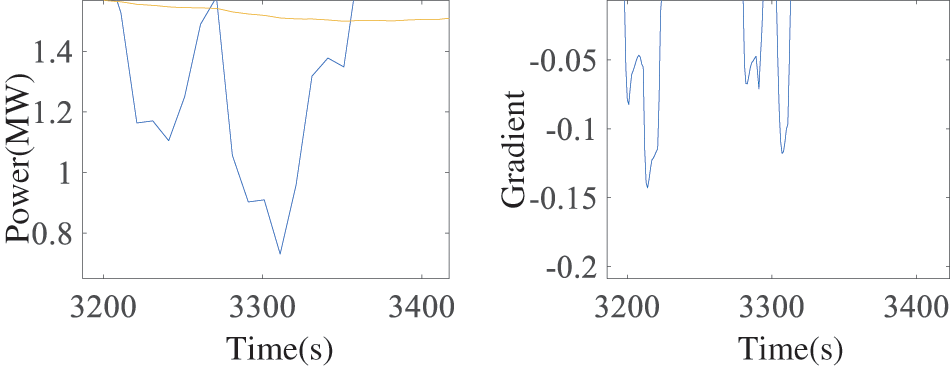
Figure 10: Zoomed-in plots below the lower limit and their gradients
As shown in Fig. 11, the discharging power of both battery energy storage and hydrogen energy storage increases as the gradient decreases. When the energy storage system discharges, it can effectively increase the power adjusted by the energy storage system.
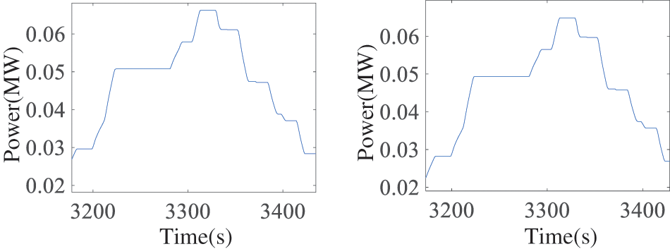
Figure 11: Battery energy storage and hydrogen energy storage discharge power
As shown in Fig. 12a, the time period between 40,000 and 60,000 s was selected to magnify the situation where wind power is within the upper and lower limit range of the grid-injected power. When the actual wind power remains within the upper and lower limit range of the grid-injected power, both the upper lagrange multiplier for exceeding the wind power upper limit and lower lagrange multiplier for exceeding the wind power lower limit are zero, and the gradient is determined by the penalty function.
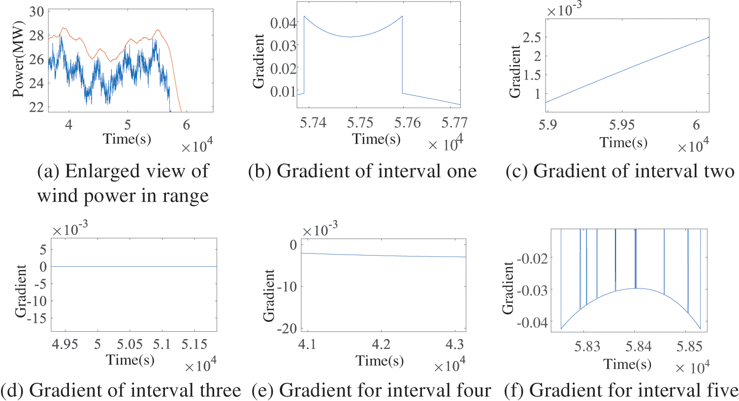
Figure 12: Enlarged view of wind power in the range and the gradient of the five intervals
When battery storage or hydrogen storage is in the first or fifth zone, the gradient is large, allowing the system to quickly battery storage move towards the third zone. When battery storage or hydrogen storage is in the second or fourth zone, the gradient is still relatively large, allowing the system to move towards the third zone at a fast pace. However, when battery storage or hydrogen storage is in the third zone, the gradient is small, and thus the system remains in this stable zone.
This shows that the proposed strategy effectively adjusts the operational state of battery and hydrogen energy storage systems through appropriate gradient control, thereby enhancing system performance and extending its lifespan.
In this paper, an online optimization strategy for a power-hydrogen hybrid energy storage system with adaptive SOC adjustment is designed, leveraging the real-time measurement of hydrogen storage and battery energy storage SOC. The main conclusions are as follows:
(1) Case study results show: before and after smoothing the fluctuations in wind power, the time when the power exceeded the upper and lower limits of the grid-injected power accounted for 24.1% and 1.45% of the total time, respectively, the proposed online optimization strategy can effectively control wind power grid integration within allowable limits, meeting the fast regulation requirements for wind power grid integration.
(2) The introduction of adaptive SOC adjustment allows hydrogen energy storage and battery storage to handle long-term and short-term charging and discharging tasks. Respectively, effectively reducing the losses from hydrogen energy storage charging and discharging, while minimizing the risk of insufficient charging and discharging in battery storage. The strategy takes into account the differences in SOC and SOH between different battery and hydrogen storage units, enabling reasonable distribution of charging and discharging power among various storage units.
(3) In the research on smoothing wind power fluctuations, this paper has not considered certain factors, such as the impact of hydrogen tank temperature on efficiency and the pressure of the hydrogen tanks. These factors need to be further addressed in future research.
Acknowledgement: I would like to express my sincere gratitude to my main supervisor, Morrone, for his invaluable guidance, support, and expertise throughout this research. I am also deeply thankful to my second supervisor, for his feedback and supervision. Their combined mentorship has been instrumental in the successful completion of this work. Lastly, I extend my appreciation to my family and friends for their unwavering encouragement and understanding during this project.
Funding Statement: Supported by State Grid Zhejiang Electric Power Co., Ltd. Science and Technology Project Funding (No. B311DS230005).
Author Contributions: The authors confirm their contribution to the paper as follows: Min Liu: Methodology, Formal Analysis; Qiliang Wu: Methodology, Formal analysis; Zhixin Li: Conceptualization, Methodology, Software, Validation, Formal Analysis, Investigation, Resources, Data Curation, Writing—Original Draft; Bo Zhao: Validation; Leiqi Zhang: Validation; Junhui Li: Writing—Review & Editing; Xingxu Zhu: Supervision, Project Administration, Funding Acquisition, Writing—Review & Editing. All authors reviewed the results and approved the final version of the manuscript.
Availability of Data and Materials: The data that support the findings of this study are available from the corresponding author upon reasonable request.
Ethics Approval: Not applicable.
Conflicts of Interest: The authors declare no conflicts of interest to report regarding the present study.
Abbreviations
| Pt.iBESS | The power of the battery unit i at time t |
| Pt.iBESS.E | The charging power of the battery unit i at time t |
| Pt.iBESS.F | The discharge power of the battery unit i at time t |
| Pt.iHESS | The power of the hydrogen unit i at time t |
| Pt.iHESS.E | The power of the electrolyzer unit i at time t |
| Pt.iHESS.F | The power of the fuel cell unit i at time t |
| N | The number of batteries |
| Mt.iH2.in | The quality of hydrogen produced by the electrolyzer unit i at time t |
| Mt.iH2.out | The quality of hydrogen consumed by the fuel cell i at time t |
| PtW.cut | Curtailment wind power at time t |
| PtW.act | The actual wind power at time t |
| Ptout | Grid-injected power deviation of wind farms with hybrid energy storage systems |
| PtW.max | Maximum wind power output |
| PtW.fore | Wind power forecast |
| PtW.up | Upper limit of the grid-injected power at time t |
| PtW.dn | Lower limit of the grid-injected power at time t |
| xup, xdn | Upper and lower limit coefficients respectively |
| λBESS | Operating cost coefficient of batteries |
| λHESS | Operating cost coefficient of hydrogen energy storage |
| CV | Operating costs of hybrid energy storage systems |
| φ(SOCt.i) | Penalty function of the state of charge of batteries |
| φ(SOHt.i) | Penalty function of the state of charge of hydrogen storage |
| Penalty factor | |
| δ1 | Battery energy storage parameters |
| δ2 | Hydrogen energy storage parameters |
| SOCt.i | The state of charge of the battery unit i at time t |
| SOCmax | The upper limit of the state of charge of a single battery |
| SOCmin | The lower limit of the state of charge of a single battery |
| SOHt.i | The hydrogen storage state at the time of the i hydrogen storage tank |
| SOHmax | The upper limit of the hydrogen storage state of the hydrogen storage tank |
| SOHmin | The lower limit of the hydrogen storage state of the hydrogen storage tank |
| Et.iBESS | The energy of the battery unit i at time t |
| ηBESS.E | The charging efficiency of a battery |
| ηBESS.F | The discharge efficiency of a battery |
| QBESS | The capacity of the battery |
| PBESS.E.max | The maximum charging power of a single battery |
| PBESS.F.max | The maximum discharge power of a single battery |
| ηelec | Production efficiency of electrolyzers |
| H | The calorific value of hydrogen |
| Pelec.max | The upper limit of the input power of a single electrolyzer |
| Pelec.min | Lower limit of input power of a single electrolyzer |
| MH2.in.max | The maximum amount of hydrogen produced per unit time by a single electrolyzer |
| QHS | The capacity of hydrogen storage tanks |
| ηFC | The efficiency of fuel cells |
| PHESS.F.max | The upper limit of the power output of a single fuel cell |
| PHESS.F.min | The lower limit of power output of a single fuel cell |
| MH2.out.max | The maximum amount of hydrogen consumed per unit time by a single fuel cell |
| L | The Lagrange function |
| f | Loss costs of electric-hydrogen hybrid energy storage systems |
| β | Step factor |
| Upper Lagrange multiplier for exceeding the wind power upper limit at time t | |
| Lower Lagrange multiplier for exceeding the wind power lower limit at time t | |
| Penalty factor for exceeding the wind power upper limit at time t | |
| Penalty factor for exceeding the wind power lower limit at time t |
Appendix A
Appendix B
The power of battery energy storage is constrained by the maximum charging and discharging power, as well as the capacity of the inverter or rectifier.
References
1. Jiang YP, Ren ZY, Li WY. Committed carbon emission operation region for integrated energy systems: concepts and analyses. IEEE Trans on Sustain Energy. 2024;15(2):1194–209. doi:10.1109/TSTE.2023.3330857. [Google Scholar] [CrossRef]
2. Yuan TJ, Guo JH, Yang ZJ, Feng Y, Wang J. Optimal allocation of power electric-hydrogen hybrid energy storage of stabilizing wind power fluctuation. Proc CSEE. 2024;44(4):1397–405. doi:10.13334/j.0258-8013.pcsee.222572 2023. [Google Scholar] [CrossRef]
3. Li ZH, Yang TQ, Shi QG, Jiang K. Research progress in modeling and state estimation of energy storage batteries. New Power System. 2024;2(2):140–61. doi:10.20121/j.2097-2784.ntps.230049. [Google Scholar] [CrossRef]
4. Li Y, Zhao J, Yang X, Wang H, Wang Y. Research on scheduling strategy of flexible interconnection distribution network considering distributed photovoltaic and hydrogen energy storage. Energy Eng. 2024;121(5):1263–89. doi:10.32604/ee.2024.046784. [Google Scholar] [CrossRef]
5. Dai WZ. Research on optimal operation of electricity-hydrogen integrated energy system. China: Shandong University; 2023. doi:10.27272/d.cnki.gshdu.2023.005432. [Google Scholar] [CrossRef]
6. Liu Q, Jia JX, Jin XF, Sun B, Wang X, Wang L. Planning of hydrogen-electric hybrid time-scale joint energy storage system based on improved double-layer robustness. Electr Measur Instrument. 2022;60(10):17–23+35. doi:10.19753/j.issn1001-1390.2023.10.003. [Google Scholar] [CrossRef]
7. Pei BH, Multi-scenario operation and capacity configuration of dual-battery-hydrogen hybrid energy storage in wind farms. China: Beijing Jiaotong University; 2023. doi:10.26944/d.cnki.gbfju.2023.000721. [Google Scholar] [CrossRef]
8. Chen FX, Lin WH, Shao ZG. Double-layer rolling optimization control method of micro-energy grid with power-to-gas and hybrid energy storage. Elect Power Automat Equip. 2022;42(5):23–31. doi:10.16081/j.epae.202202017. [Google Scholar] [CrossRef]
9. He GX, Lv HS, Liang ZC, Yang D, Liao Q, Liu Y. Response control strategy of centralized hybrid energy storage system in park. Renew Energy. 2018;36(9):1341–7. doi:10.13941/j.cnki.21-1469/tk.2018.09.013. [Google Scholar] [CrossRef]
10. Zhang C, Feng ZN, Deng SP, Jia C, Lu S. Considering multi-energy complementary collaborative peak shaving and valley filling strategy for electric-thermal hybrid energy storage. Transact China Electrotech Soc. 2021;36(S1):191–9. doi:10.19595/j.cnki.1000-6753.tces.L90405. [Google Scholar] [CrossRef]
11. Ashfaq S, Myasse I, Zhang D, Musleh A, Liu B, Telba A, et al. Comparing the role of long duration energy storage technologies for zero-carbon electricity systems. IEEE Access. 2024;12:73169–73186. doi:10.1109/ACCESS.2024.3397918. [Google Scholar] [CrossRef]
12. Ashfaq S, Myasse I, Musleh A, Zhang D, Dong Z. Least cost analysis of bulk energy storage for deep decarbonized power system with increased share of renewable energy. Elect Power Syst Res. 2023;220(4):109375. doi:10.1016/j.epsr.2023.109375. [Google Scholar] [CrossRef]
13. Jiang ZL, Hao FJ, Yuan ZC, Zhu X, Guo P, Pan H, et al. Operation optimization of electric-hydrogen hybrid energy storage system considering SOC optimization setting. Power Syst Protect Cont. 2024;52(8):65–76. doi:10.19783/j.cnki.pspc.231371. [Google Scholar] [CrossRef]
14. Wang YX, Jiang LY, Fan XF. Research on power allocation strategy of DC microgrid system based on hydrogen energy storage. Therm Pow Generat. 2023;52(11):105–14. doi:10.19666/j.rlfd.202305090. [Google Scholar] [CrossRef]
15. Chi YX, Zhao ZG, Xu HW, Chang T. Control strategy of hybrid energy storage of flywheel and battery in wind power system. J Shenyang Instit Technol. 2022;18(1):12–9. doi:10.13888/j.cnki.jsie(ns).2022.01.003. [Google Scholar] [CrossRef]
16. Peng XZ, Research on optimization strategy of multi-integrated energy system considering wind and solar consumption. North China Electric Power University; 2023. doi:10.27139/d.cnki.ghbdu.2023.000029. [Google Scholar] [CrossRef]
17. Wu MX, Fang F. Robust optimization of the distribution of electricity-heat-hydrogen integrated energy system considering the uncertainty of wind and solar. Transact China Electrotech Soc. 2023;38(13):3473–85. doi:10.19595/j.cnki.1000-6753.tces.220759. [Google Scholar] [CrossRef]
18. Wu YJ, Autonomous operation strategy of multi-source microgrid for hybrid energy storage with electric hydrogen. China: Taiyuan University of Science and Technology; 2021. doi:10.27721/d.cnki.gyzjc.2021.000035. [Google Scholar] [CrossRef]
19. Dai Y, Li H, Li B. Research on the control strategy of micro wind-hydrogen coupled system based on wind power prediction and hydrogen energy storage system charging/discharging regulation. Energy Eng. 2022;121(6):1607–36. doi:10.32604/ee.2024.047255. [Google Scholar] [CrossRef]
20. Guo IH, Optimal operation of power system with electricity-hydrogen hybrid energy storage. China: Dalian University of Technology; 2022. doi:10.26991/d.cnki.gdllu.2022.001104. [Google Scholar] [CrossRef]
21. Ma WZ, Wang LB, Wang YS, Wan R, Wang X, Wang J. Hybrid energy storage power allocation and adaptive virtual inertial control considering SOC. Power Syst Protect Cont. 2024;52(5):83–93. doi:10.19783/j.cnki.pspc.230968. [Google Scholar] [CrossRef]
22. Cui GQ, Liu YL, Zeng LR. Power distribution strategy of hybrid energy storage system considering supercapacitor SOC. Distrib Energy. 2023;8(3):1–9. doi:10.16513/j.2096-2185.DE.2308301. [Google Scholar] [CrossRef]
23. Liu YQ, Lei WJ, Liu Q, Gao Y, Dong M. Joint state estimation of lithium-ion battery based on dual adaptive extended particle filter. Transact China Electrotech Soc. 2024;39(2):607–16. doi:10.19595/j.cnki.1000-6753.tces.222357. [Google Scholar] [CrossRef]
24. Zhou BX, Zou JH, Dong S, Liao M, Zhang Z. Energy collaborative optimization of microgrid park system based on shared energy storage. Elect Drive. 2021;51(18):70–5. doi:10.19457/j.1001-2095.dqcd21446. [Google Scholar] [CrossRef]
25. Jiang YW, Yang GM, Chen YX, Huang W. Optimization of hydrogen network operation considering dynamic hydrogen production efficiency of electrolyzer. Proc CSEE. 2023;43(8):3014–26. doi:10.13334/j.0258-8013.pcsee.212956. [Google Scholar] [CrossRef]
26. Huang WH, Yu QR, Wang J, Zhang J, Sun N, Huang H. Design of proton exchange membrane fuel cell controller based on TC275. Modern Electr Technol. 2024;47(18):22–8. doi:10.16652/j.issn.1004-373x.2024.18.004. [Google Scholar] [CrossRef]
27. Cui Y, Sun XB, Zhu H, Xu Y, Wang S, Yu S, Zhao Y. Considering the low-carbon economic dispatch of an integrated energy system with “coal+” coupling power generation and flexible resource backup. Proc CSEE. 2024. doi:10.13334/j.0258-8013.pcsee.241219. [Google Scholar] [CrossRef]
Cite This Article
 Copyright © 2025 The Author(s). Published by Tech Science Press.
This work is licensed under a Creative Commons Attribution 4.0 International License , which permits unrestricted use, distribution, and reproduction in any medium, provided the original work is properly cited.
 Downloads
 Citation Tools