
 Submit a Paper
 Propose a Special lssue
 Open Access
ARTICLE

Synchronization Characterization of DC Microgrid Converter Output Voltage and Improved Adaptive Synchronization Control Methods
School of Electrical Engineering and Information Engineering, Lanzhou University of Technology, Lanzhou, 730050, China
* Corresponding Author: Xin Gao. Email:
(This article belongs to the Special Issue: Emerging Technologies for Future Smart Grids)
Energy Engineering 2025, 122(2), 805-821. https://doi.org/10.32604/ee.2025.059779
Received 16 October 2024; Accepted 19 December 2024; Issue published 31 January 2025
 View Full Text
 Download PDF
Abstract
This paper deeply introduces a brand-new research method for the synchronous characteristics of DC microgrid bus voltage and an improved synchronous control strategy. This method mainly targets the problem of bus voltage oscillation caused by the bifurcation behavior of DC microgrid converters. Firstly, the article elaborately establishes a mathematical model of a single distributed power source with hierarchical control. On this basis, a small-world network model that can better adapt to the topology structure of DC microgrids is further constructed. Then, a voltage synchronization analysis method based on the main stability function is proposed, and the synchronous characteristics of DC bus voltage are deeply studied by analyzing the size of the minimum non-zero eigenvalue. In view of the situation that the line coupling strength between distributed power sources is insufficient to achieve bus voltage synchronization, this paper innovatively proposes a new improved adaptive controller to effectively control voltage synchronization. And the convergence of the designed controller is strictly proved by using Lyapunov’s stability theorem. Finally, the effectiveness and feasibility of the designed controller in this paper are fully verified through detailed simulation experiments. After comparative analysis with the traditional adaptive controller, it is found that the newly designed controller can make the bus voltages of each distributed power source achieve synchronization more quickly, and is significantly superior to the traditional adaptive controller in terms of anti-interference performance.Keywords
Nomenclature
| DC input voltage | |
| Switch tube | |
| Converter inductance current | |
| Converter capacitance voltage | |
| Switch tube status | |
| Distributed power supply | |
| Power difference | |
| DC bus bar voltage | |
| Bus bar reference voltage | |
| Current reference signal | |
| The droop coefficient of the power | |
| The droop coefficient of the power | |
| Voltage input in the secondary control | |
| Voltage ring proportional coefficient | |
| Voltage loop integral coefficient | |
| PWM trigger signal | |
| Current ring proportional coefficient | |
| Current ring integral coefficient | |
| Current ring integral coefficient | |
| Coupling strength | |
| Internal coupling matrix | |
| The degree of the node | |
| The Laplacian matrix of the network | |
| Probability of broken edge reconnection | |
| Synchronize the popular space | |
| Eigenvalues of the matrix L | |
| Maximum Lyapunov exponent of L matrix | |
| The synchronous region of the network | |
| Synchronization error | |
| Custom constants | |
| Synchronous variance |
The DC microgrid passes through only one level of the DC-DC voltage converter between each distributed power source and the load, which effectively reduces the power transmission loss and has a low system cost and high reliability [1,2]. Multiple DC-DC converters are internally connected according to a certain topology to form a small power supply network [3,4]. Voltage amplitude stability in a DC microgrid is an important measure of voltage quality, and it is also key to the reliable operation of a DC microgrid system [5,6]. Therefore, the output voltage synchronization of the converter is an important prerequisite for the stable operation of the DC microgrid system. At the same time, the controller design and energy management of the DC microgrid is also the key factors to maintain the stable operation of the microgrid, and the appropriate energy storage configuration and efficient energy management system can realize the dynamic balance between the distributed energy supply and the diversified load demand of the microgrid. A new energy management algorithm and a multi-objective nonlinear controller in the microgrid environment of the gym was proposed in Reference [7] to achieve a dynamic balance between the intermittent power generation of distributed generators and the randomness of load changes.
In DC microgrid, many studies focus on the output energy distribution of distributed generators and the stable control of bus voltage. Reference [8] proposes an improved hierarchical control method for DC microgrid, which realizes the balanced distribution of load power and the stability control of bus voltage through the coordination between controllers. In Reference [9], a distributed controller based on virtual voltage difference was designed, and voltage stabilization and power distribution could be achieved simultaneously through the global sharing of virtual voltage difference. In Reference [10], a droop control method was designed based on the reference voltage deviation on the basis of considering the energy storage unit, which realized the dynamic balance between the load and the power supply and the unbiased control of the bus voltage. Reference [11] proposes an adaptive virtual inertial control method for DC microgrid bus voltage, which solves the problem of small interference oscillation of bus voltage and bus voltage offset under large interference. Reference [12] proposes an adaptive droop control strategy based on the state of charge of the battery, which realizes the smooth switching of the DC microgrid system in different working modes and can maintain the stability of the bus voltage. In the context of islanded DC microgrids, a distributed cooperative control strategy considering the voltage regulation and economic dispatching objectives was proposed in Reference [13], which realized bus voltage stability and optimal load distribution under the condition of considering energy storage constraints. The above literature proposes many stability control methods for DC microgrid bus voltage, but the influence of the complex topology of DC microgrid compared with traditional power grid on the synchronization characteristics of DC bus voltage is not fully considered.
Currently, the state-space method and the coupled synchronization method based on state equations or the Kuramoto model is mainly used for the synchronization characterization of microgrid systems. Bellini et al. proposed a method to synchronize the output voltage of microgrid converters by cascading coupled power lines under the microgrid islanding operation mode [14]. References [15,16] take the output voltage of the generator set as a reference for the output voltage of the microgrid converter to realize the tracking and synchronization of the microgrid bus voltage. Reference [17] explores how the interaction between DC microgrid converters affects their voltage synchronization characteristics. The mechanism by which the dynamic interaction between DC microgrid converters affects the voltage stability of the bus is reported. However, the interconnected DC microgrid system, which utilizes multiple DC-DC converters in a specific topology, exhibits an intricate nonlinear behavior [18]. This complexity leads to challenges in synchronizing the output voltage oscillation of converters and poses new obstacles for ensuring the stability and control of the bus voltage within the DC microgrid system [19,20]. Reference [21] used microgrid converters as network nodes and studied the bifurcation phenomenon of converters and the coupling synchronization method of the bus voltage of a photovoltaic microgrid system. In Reference [22], authors investigated the effect of microgrid topology on network synchronization stability based on Kuramoto’s first-order model and provided a formula for the critical coupling strength after adding new connections and new node units to the microgrid. Reference [23] investigates the effect of adding new connections on voltage synchronization in power networks, and the results show that increasing the number of nonuniformly connected edges is positively correlated with the voltage synchronization performance. Moreover, a microgrid, as a new type of electric energy network, has a topology with small-world characteristics in complex networks, and the synchronization problem among its nodes has attracted extensive attention from many scholars [24−26]. Reference [27] investigated the enhancement of voltage synchronization characteristics by changing the switching state of circuit breakers to change the topology of the entire power network. Literature [28] shows that shortcuts in small-world networks enhance the synchronization characteristics of power networks. Reference [29] investigated the impact of power network structure on the vulnerability of transmission networks from the perspective of network hierarchy characteristics and their relationships. The above literature mainly focuses on the effect of the power grid structure on voltage synchronization, whereas, the strong nonlinear characteristics of microgrid converters have not been considered fully in the analysis process.
In the above literature, References [14–17] have studied the bus voltage oscillation of microgrid, but not the asynchronous bus voltages caused by the topological connection relationship of microgrids. In order to solve the problem that the synchronization method of bus voltage in References [21–23] has certain limitations and is not suitable for DC microgrid, this paper proposes a principal stability function analysis method suitable for the study of bus voltage synchronization characteristics of DC microgrids. References [27–29] only study the synchronization characteristics of bus voltages from the perspective of complex networks, but they do not provide appropriate control methods for the phenomenon of failure to achieve synchronization. In view of the shortcomings of the above literature, this paper proposes an improved adaptive synchronous control method for DC microgrid bus voltage control for the first time, and the bus voltage realizes synchronous control and oscillation suppression.
In this paper, we focus on a DC microgrid with hierarchical control and study the influence of the structural parameters in the network on the synchronization characteristics of converter output voltages based on the master stabilization function method and a small-world network model, to better control the DC microgrid bus voltage oscillation caused by converter bifurcation behavior. With respect to the voltage desynchronization phenomenon caused by the capacity limitation of the contact line, a new improved adaptive synchronization control method was developed. This control method can quickly realize voltage synchronization between converter nodes in a DC microgrid small-world network.
The innovation of this paper is mainly in the following three aspects:
1. A new modeling method of DC microgrid based on complex network is proposed to adapt to the actual topology of DC microgrid.
2. A new principal stability function method suitable for DC microgrid bus voltage synchronization is applied to study the synchronization characteristics of DC bus voltage synchronization.
3. A new and improved adaptive controller is designed for synchronous control and oscillation suppression of DC bus voltage.
The remainder of this paper is organized as follows: Section 2 builds a small-world network model based on a hierarchically controlled DC microgrid; Section 3 analyzes the synchronization characteristics of the converter output voltages based on the master stability function method; Section 4 investigates the improved adaptive synchronization control for DC microgrid small-world networks; Section 5 verifies the theoretical analysis via simulation; and Section 6 concludes the paper.
2 Small-World Network Model for DC Microgrids
2.1 Hierarchically Controlled DC Microgrid Modeling
The hierarchical control principle of a DC microgrid operating in isolated island mode is shown in Fig. 1. The main circuit adopts a buck-boost converter with the functions of both boost and buck [30]. The control system adopts a hierarchical control structure, in which the first layer control transmits the collected load feedback signal to the droop controller and the voltage and current double loop controller for the initial adjustment of the output; since the droop control is a differential regulation, the improved adaptive control is used in the two-layer control to compare the collected voltage signal with the given reference value and obtain the deviation value to eliminate the error of the droop control. The voltage signal deviation is obtained to eliminate the droop control error. Finally, the signal obtained by the dual-loop controller is fed into the PWM controller, and the trigger signal of the switching tube
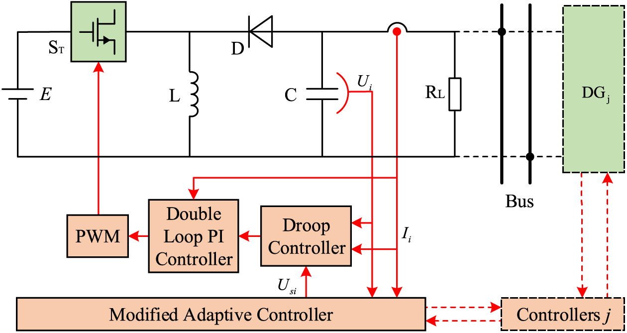
Figure 1: Hierarchically controlled DC microgrid model
In the main circuit part of Fig. 1, E is the input DC voltage of the converter,
where
Depending on the value of the PWM signal controlling the on-off of
In Eq. (2), when the output logic value of the Q terminal of the RS flip-flop is 1,
Droop control is used in the primary control system shown in Fig. 1. In the
When the difference between the power provided by the distributed power source and the load power is generated, the bus voltage will fluctuate to balance the power in each DG system. Therefore, the bus voltage and power difference
In the above equation,
where
Consider the voltage input
where
In Eq. (8),
where
2.2 DC Microgrid Small-World Network Modeling
Consider a DC microgrid system network consisting of N identical converters, where each network node is a dynamical system determined by a piecewise linear model of its main circuit. The information of the node can be adopted by its neighboring nodes, the coupling point is the output port of the converter, and the linear coupling method is used to establish the state equation of the small-world network of the whole system [31]:
In Eq. (10), the state variables of the nodes
The Laplacian matrix corresponding to the converter network defined by the adjacency matrix
Then, Eq. (10) can be rewritten in the following form:
The small-world network model is built from a single DG of a DC microgrid as a node to analyze the voltage synchronization characteristics of a DC microgrid under different network models. Fig. 2 shows the structure of the DC microgrid small-world network model, and its construction method is to establish the proximity-coupled network initially. On this basis, the original connecting edges are disconnected with probability P to increase the number of new connecting edges constructed from the relationship.
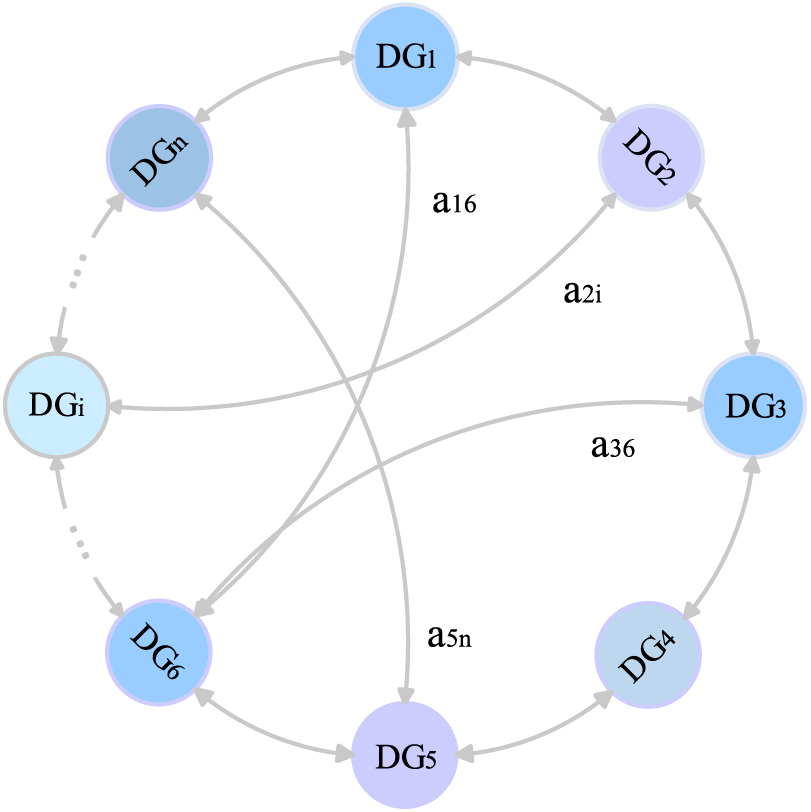
Figure 2: Small-world network model of a DC microgrid converter
3 Synchronized Output Voltage Characterization Method Based on the Principal Function Stabilization Method
The synchronized manifold of the DC microgrid converter network model (12) is a linear subspace in
In this paper, voltage synchronization analysis of DC microgrid small-world networks is based on the master stability function method proposed by Sivaganesh [32]. The network satisfies the following conditions: ① all DG nodes have the same dynamics equations; ② the coupling functions between each converter node are the same; ③ the synchronization pop is constant and can be linearized near the steady-state solution. From this, the network model (12) can be variationally differentiated such that
In Eq. (13), the Jacobian matrices of functions
Obviously, the matrix
Considering that the
Then, the region in Eq. (16) with the maximum Lyapunov exponent
For the case where the synchronization region is unbounded,
4 Improved Adaptive Synchronization Control for DC Microgrid Small-World Networks
For the actual network constituted by the converter, the coupling strength is limited by objective factors such as the line capacity, which cannot be increased indefinitely; at this time, it is necessary to use control methods to synchronize the voltage amplitude. Under the linear coupling function, the adaptive controller can synchronize the output voltage of each node, but the control effect is poor. In this paper, by improving the adaptive controller, the voltage of the whole DC microgrid with a better synchronization effect than adaptive control has been achieved.
Consider a small-world network with linear dissipative coupling consisting of N identical converter nodes with controlled network equations:
The synchronization error of the voltage of the network can be written as:
Adaptive controllers are added to each node in the converter network in the following form:
An improved adaptive controller is applied to each node in the converter network in the following form:
The linearization of the error in the neighborhood of the steady-state solution is obtained:
Suppose there is a positive constant
The proof procedure is as follows. For the above system, the Lyapunov function is constructed as follows:
Then:
To make
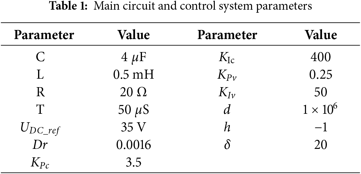
To verify the correctness and feasibility of the analysis and control methods proposed in this paper, simulation verification is carried out below. Under the small-world network structure of a DC microgrid with hierarchical control, the bifurcation behavior of converters and the effects of different reconnection edge probabilities, coupling strengths, and network sizes on the voltage synchronization characteristics of DC microgrids under the small-world network structure are analyzed. The system parameters selected are shown in Table 1.
A bifurcation diagram with
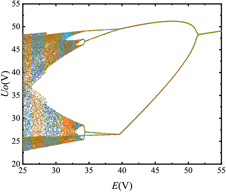
Figure 3: Bifurcation of the converter output voltage
A DC microgrid small-world network model is established to simulate and verify its voltage amplitude synchronization characteristics. The Ode45 method is adopted to solve the differential equation system of the converter nodes, with an integration step of h = 1 × 10⁻⁶ s and network parameters of N = 10 and P = 0.2.
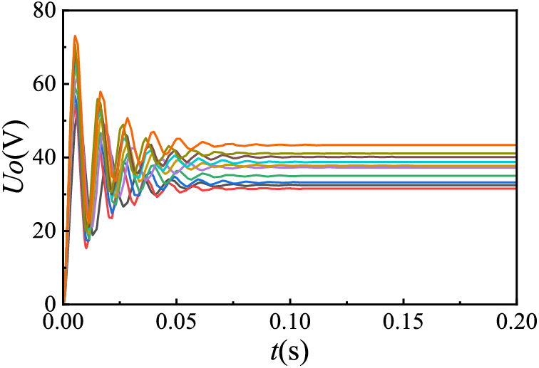
Figure 4: Timing diagram of the transformer output voltage magnitude (k = 0)

Figure 5: Timing diagram of the transformer output voltage magnitude (k = 1)

Figure 6: Timing diagram of the transformer output voltage magnitude (k = 2)
As can be seen from Figs. 4 to 6, in a 10-node microgrid network, when k = 0, the voltage between the converters cannot be synchronized at all, when k = 1, the synchronization deviation between the voltages of each node decreases to ±4 V, and when k = 2, the voltage synchronization deviation of each node decreases to ±2.5 V. From the data analysis, it can be seen that with the increase of the coupling strength between each node, the synchronization deviation of the bus voltage of each node of the microgrid has a significant decreasing trend.
To observe the synchronization characteristics of each converter node voltage more intuitively, this paper compares the synchronization performance of the DC microgrid converter voltage amplitude using variance, which is defined as follows [33]:
where
As can be seen from Fig. 7, when k = 5, the maximum value of voltage synchronization variance reaches the maximum value of

Figure 7: Voltage synchronization variance time series plot for different coupling strengths
The Laplacian matrix of the DC microgrid small-world network structure can be obtained from the definition of Eq. (4) combined with the converter network structure. The variations in the eigenvalues of the Laplacian matrix of the small-world network with the number of nodes at different P values are calculated via MATLAB, and the results are shown in Fig. 8. The synchronization ability of the DC microgrid small-world network decreases as the network size increases. For the same number of converter nodes,
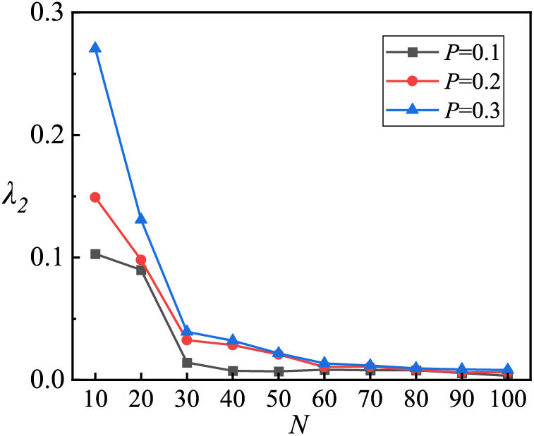
Figure 8: Minimum non-zero eigenvalue variation with network size
To better study the synchronization of the DC microgrid small-world network model system, the synchronization time change rule with the network size is studied by a numerical calculation method with node N as the change parameter. The synchronization time of the output voltage of each node of the converter of the DC microgrid small-world network model under different reconnection edge probabilities is shown in Fig. 9. In the 10-node microgrid network, when P = 0.1 increases to 0.3, the voltage synchronization time of each node is about 0.012 s due to the small scale of the network. When the network size increases to 40 nodes, from P = 0.1 to P = 0.2, the voltage synchronization time decreases from 0.16 to 0.06 s, and from 0.06 to 0.04 s when the reconnect probability from P = 0.2 to P = 0.3. When the network size increases to 100 nodes, from P = 0.1 to P = 0.2, the voltage synchronization time decreases from 0.37 to 0.28 s, and the voltage synchronization decreases from 0.28 to 0.18 s when the reconnect probability from P = 0.2 to P = 0.3. Through the comparative analysis of the data, it can be seen that with the increase of the number in nodes, the output voltage synchronization time increases, but with the increase of the reconnection probability, the output voltage synchronization time is shorter under the same network scale.
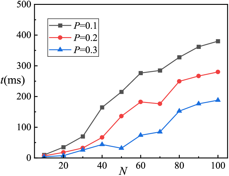
Figure 9: Variation in the output voltage synchronization time with network size
The control performance of the DC microgrid’s second layer control of the converter using improved adaptive control and adaptive control is analyzed in the following figures by comparison. The simulation of the second layer control using adaptive control is shown in Fig. 10; the simulation of the second layer control using improved adaptive control is shown in Fig. 11. In both control modes, to facilitate the comparison of their control performance, the coupling strength is k = 1, the rest of the circuit parameters are the same as the aforementioned parameters, the control is applied at t = 0.06 s, and a unit step perturbation is applied to the node voltage at t = 0.1 s to test the immunity performance of the controller.

Figure 10: DC microgrid converter adaptive control

Figure 11: Improved adaptive control of DC microgrid converters
Compared with Figs. 10 and 11, it can be observed that the voltage deviation of each node is ±0.65 V and gradually decreases when the traditional adaptive controller is applied at t = 0.06 s, the bus voltage fluctuation is ±0.48 V when the input voltage is disturbed at t = 0.09 s, and the synchronization error of the bus voltage is still 0.12 V at t = 0.2 s, and the voltage deviation of each node is ±0.46 V and gradually decreases rapidly when the improved adaptive controller designed in this paper is applied at t = 0.06 s. When the input voltage is disturbed at t = 0.09 s, the bus voltage fluctuation is only ±0.17 V, and the synchronization error of the bus voltage is only ±0.05 V when t = 0.15 s. Through comparison, it is found that the output voltage of the DC microgrid converter network can be synchronized under the two control modes, but the improved adaptive control has a better control effect. When the input voltage of one of the nodes fluctuates, the fluctuation of the converter output voltage is smaller under the improved adaptive control, and it can also quickly restore the smoothness.
In the following, the perturbation resistance analysis of the above model is performed. The primary layer control of the microgrid is droop control, where
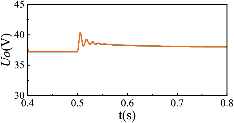
Figure 12: Adaptive control perturbation map

Figure 13: Improved adaptive control perturbation map
In this paper, a small-world network model of a DC microgrid is established based on hierarchical control. The effects of the coupling strength and node connection relationship on the voltage synchronization characteristics and voltage synchronization control method are investigated. Based on References [14–17], this paper considers the complex topology of DC microgrid, establishes an adaptable small-world network model, and proposes a principal stability function method suitable for the analysis of the voltage synchronization characteristics of DC microgrid bus based on References [21–23]. Based on References [27–29], an improved adaptive voltage synchronous control method is proposed, and the following conclusions are drawn through simulation comparison and analysis with the traditional adaptive control method:
(1) With increasing coupling strength and connection edges between converter nodes, the voltage synchronization performance of the DC microgrid small-world network is enhanced, and the bus voltages tend to be synchronized. In the microgrid network model, when the coupling strength k = 50, the amplitude of the voltage synchronization error of each node is controlled within 0.5%. When the reconnection probability P = 0.3, for a typical 100-node microgrid network, the voltage synchronization of each node is reached in 0.18 s.
(2) Hierarchical control of DC microgrid system voltage secondary control using improved adaptive control can eliminate the voltage difference of droop control faster than adaptive control and has better anti-interference performance. The voltage fluctuation of the improved adaptive controller designed in this paper is only ±0.6 V under disturbance, which is 3.8 V lower than that of the traditional adaptive control, and the unbiased control of the bus voltage is realized within 0.05 s, which is 0.12 s faster than the traditional adaptive controller.
Acknowledgement: None.
Funding Statement: This research was supported by the National Natural Science Foundation of China (Nos. 51767017 and 51867015), the Basic Research and Innovation Group Project of Gansu (No. 18JR3RA13), and the Major Science and Technology Project of Gansu (No. 19ZD2GA003).
Author Contributions: The authors confirm contribution to the paper as follows: study conception and design: Wei Chen, Xin Gao; data collection: Xin Gao, Xusheng Yang, Zhao Li; analysis and interpretation of results: Wei Chen, Zhanhong Wei; draft manuscript preparation: Xusheng Yang, Zhanhong Wei. All authors reviewed the results and approved the final version of the manuscript.
Availability of Data and Materials: The authors confirm that the data supporting the findings of this study are available within the article.
Ethics Approval: Not applicable.
Conflicts of Interest: The authors declare no conflicts of interest to report regarding the present study.
References
1. Gui Y, Han R, Guerrero JM, Vasquez JC, Wei B, Kim W. Large-signal stability improvement of DC-DC. IEEE Trans Energy Convers. 2021;36(3):2534–44. doi:10.1109/TEC.2021.3057130. [Google Scholar] [CrossRef]
2. Sahoo SK, Sinha AK, Kishore NK. Control techniques in AC, DC, and hybrid AC-DC microgrid: a review. IEEE J Emerg Select Topics Power Electron. 2018;6(2):738–59. doi:10.1109/JESTPE.2017.2786588. [Google Scholar] [CrossRef]
3. Jiang W, Wang M, Li X, Xu Z, Zhang X, Wu X. Autonomous finite-time backstepping control for decentralized economic power dispatch in DC microgrids. Toward large-signal stability. IEEE Trans Ind Electron. 2024;71(3):2942–54. doi:10.1109/TIE.2023.3262880. [Google Scholar] [CrossRef]
4. Liu H, Guo W, Cheng D, Wang Y, Wang M. Stability and bifurcation analysis of DC microgrid with multiple droop control sources and loads. IEEE Trans Power Electron. 2021;36(2):2361–72. doi:10.1109/TPEL.2020.3009192. [Google Scholar] [CrossRef]
5. Xu Q, Vafamand N, Chen L, Dragičević T, Xie L, Blaabjerg F. Review on advanced control technologies for bidirectional DC/DC converters in DC microgrids. IEEE J Emerg Sel Top Power Electron. 2021;9(2):1205–21. doi:10.1109/JESTPE.2020.2978064. [Google Scholar] [CrossRef]
6. Xu L, Guerrero JM, Lashab A, Wei B, Bazmohammadi N, Vasquez JC, et al. A review of DC shipboard microgrids-Part I: power architectures, energy storage, and power converters. IEEE Trans Power Electron. 2022;37(5):5155–72. doi:10.1109/TPEL.2021.3128417. [Google Scholar] [CrossRef]
7. Azzab AE, Magri AE, Myasse IE, Lajouad R, Watil A, Ouabi H. Energy management in gyms microgrid: nonlinear control of stationary bikes and treadmills with parallel rectifiers and AC/DC conversion. e-Prime-Adv Electr Eng Electron Energy. 2024;9(9):100680. doi:10.1016/j.prime.2024.100680. [Google Scholar] [CrossRef]
8. Wang P, Lu X, ang XY, Wang W, Xu D. An improved distributed secondary control method for DC microgrids with enhanced dynamic current sharing performance. IEEE Trans Power Syst. 2016;31(9):6658–73. doi:10.1109/TPEL.2015.2499310. [Google Scholar] [CrossRef]
9. Xing L, Mishra Y, Guo F, Lin P, Yang Y, Ledwich G, et al. Distributed secondary control for current sharing and voltage restoration in DC microgrid. IEEE Trans Smart Grid. 2020;11(3):2487–97. doi:10.1109/TSG.2019.2956515. [Google Scholar] [CrossRef]
10. Zhang Q, Zeng Y, Liu Y, Zhuang X, Zhang H, Hu W, et al. An improved distributed cooperative control strategy for multiple energy storages parallel in islanded DC microgrid. IEEE J Emerg Sel Topics Power Electron. 2022;10(1):455–68. doi:10.1109/JESTPE.2021.3072701. [Google Scholar] [CrossRef]
11. Weng LT, Yang L, Lei ZY, Huang ZH, Chen YQ. Integrated bus voltage control method for DC microgrids based on adaptive virtual inertia control. J Power Electron. 2024;4(24):565–72. doi:10.1007/s43236-024-00785-6. [Google Scholar] [CrossRef]
12. Dai L, Wang JR, Tan L, Zhu XQ, Wang M, Dou S. Research on control Strategy of PV storage DC microgrid based on adaptive droop Control. Acta Energiae Solaris Sinica. 2024;8(45):154–63. doi:10.3390/en17061454. [Google Scholar] [CrossRef]
13. Zeng YJ, Zhang QJ, Liu YC, Guo HH, Zhang FK. Distributed cooperative control strategy for stable voltage restoration and optimal power sharing in Islanded DC microgrids. IEEE Trans Power Syst. 2024;2(39):3431–43. doi:10.1109/TPWRS.2023.3274932. [Google Scholar] [CrossRef]
14. Bellini A, Bifaretti S, Giannini F. A robust synchronization method for centralized microgrids. IEEE Trans Indus Appl. 2015;51(2):1602–9. doi:10.1109/ECCE.2013.6647315. [Google Scholar] [CrossRef]
15. Guo X, Li Y, Xie X, Hou Y, Zhang D. Sub-synchronous oscillation characteristics caused by PMSG-based wind plant farm integrated via flexible HVDC system. Proc CSEE. 2020;40(4):1149–60. doi:10.1109/TSTE.2020.3035203. [Google Scholar] [CrossRef]
16. Gao B, Yao L, Ren L, Zhao S, Yang L. Analysis on oscillation modes of large-scale grid-connected PV power plant. Elect Power Autom Equip. 2017;37(8):123–30. [Google Scholar]
17. Zhu X, Li Z, Meng F. Stability analysis of dc microgrid based on different grid structures. Trans China Electrotech Soc. 2021;36(1):166–78. [Google Scholar]
18. Sun S, Tang C, Xie D, Gu C, Zhang Y. Dynamic stability analysis of DC microgrid and construction of stability region of control parameters based on Pioncare map. Int J Electri Power Energy Syst. 2023;15:109107. doi:10.1016/j.ijepes.2023.109107. [Google Scholar] [CrossRef]
19. Cheng C, Xie F, Zhang B. Modeling and nonlinear dynamic analysis of cascaded DC-DC converter systems based on simplified discrete mapping. IEEE Trans Ind Electron. 2023;70(6):5830–9. doi:10.1109/TIE.2022.3192684. [Google Scholar] [CrossRef]
20. Ma W, Zhang B. Periodic time-triggered hybrid control for dc-dc converter based on switched affine system model. IEEE Trans Ind Electron. 2023;70(1):311–21. doi:10.1109/TIE.2022.3150085. [Google Scholar] [CrossRef]
21. Liao Z, Luo X. Research on synchronous method for photovoltaic supplied micro-grid based on small-world network model. Acta Phys Sin. 2014;63(23):23050201–06. doi:10.7498/aps.63.230502. [Google Scholar] [CrossRef]
22. Yu C. Research on synchronization stability ptimization and control of heterogeneous. Microgrids based on complex network theory [dissertation]. Wuhan, China: Wuhan University; 2020. [Google Scholar]
23. Huang JH, Yang JH, Xie DS, Wu DQ. Optimal sliding mode chaos control of direct-drive wave power converter. IEEE Access. 2019;7:90922–30. doi:10.1109/ACCESS.2019.2925470. [Google Scholar] [CrossRef]
24. Meng Z, Lu Z, Song J. Comparison analysis of the small-world topological model of Chinese and American power grids. Autom Electr Power Syst. 2004;28(15):21–4+29. [Google Scholar]
25. Zhang Y, Kang Z, Li X. The controllability of power grids in comparison with classical complex network models. IECE Trans Inform Syst. 2016;39(1):279–82. doi:10.1587/transinf.2015EDL8207. [Google Scholar] [CrossRef]
26. Gu KS, Guk YS. Topological and statistical analysis for the high-voltage transmission networks in the korean power grid. Korean Ins Commun Inform Sci. 2017;42(4):923–31. doi:10.7840/kics.2017.42.4.923. [Google Scholar] [CrossRef]
27. Huang W, Hill DJ, Zhang X. Small-disturbance voltage stability of power systems: dependence on network structure. IEEE Trans Power Syst. 2020;35(4):2609–18. doi:10.1109/TPWRS.2019.2962555. [Google Scholar] [CrossRef]
28. Chen G. Searching for best network topologies with optimal synchronizability: a brief review. IEEE/CAA J Automa Tica Sinica. 2022;9(4):573–7. doi:10.1109/JAS.2022.105443. [Google Scholar] [CrossRef]
29. Luo L, Han B, Rosas-Casals M. Network hierarchy evolution and system vulnerability in power grids. IEEE Syst J. 2018;12(3):2721–8. doi:10.1109/JSYST.2016.2628410. [Google Scholar] [CrossRef]
30. Saafan AA, Khadkikar V, Moursi MSEl, Zeineldin HH. A new multiport DC-DC converter for DC microgrid applications. IEEE Trans Ind Appl. 2023;59(1):601–11. doi:10.1109/TIA.2022.3213235. [Google Scholar] [CrossRef]
31. Liu B, Li Z, Chen X, Huang Y, Liu X. Recognition and vulnerability analysis of key nodes in power grid based on complex network centrality. IEEE Trans Circuits Systems II: Express Briefs. 2018;65(3):346–50. doi:10.1109/TCSII.2017.2705482. [Google Scholar] [CrossRef]
32. Sivaganesh G. Master stability functions for a class of coupled simple nonlinear electronic circuits. J Korean Phys Soc. 2016;68(5):628–32. doi:10.3938/jkps.68.628. [Google Scholar] [CrossRef]
33. Chen XK, Li SL, Zhang ZD, Bi QS. Relaxation oscillations induced by an order gap between exciting frequency and natural frequency. Sci China Technol Sci. 2017;60(1):289–98. doi:10.1007/s11431-015-0839-2. [Google Scholar] [CrossRef]
Cite This Article
 Copyright © 2025 The Author(s). Published by Tech Science Press.
This work is licensed under a Creative Commons Attribution 4.0 International License , which permits unrestricted use, distribution, and reproduction in any medium, provided the original work is properly cited.
 Downloads
 Citation Tools