 Open Access
ARTICLE
Integrated Equipment with Functions of Current Flow Control and Fault Isolation for Multiterminal DC Grids
1 School of Electrical Engineering, Shandong University, Jinan, 250061, China
2 Suzhou Research Institute, Shandong University, Suzhou, 215123, China
* Corresponding Author: Guibin Zou. Email:
Energy Engineering 2025, 122(1), 85-99. https://doi.org/10.32604/ee.2024.057452
Received 18 August 2024; Accepted 25 September 2024; Issue published 27 December 2024
Abstract
The multi-terminal direct current (DC) grid has extinctive superiorities over the traditional alternating current system in integrating large-scale renewable energy. Both the DC circuit breaker (DCCB) and the current flow controller (CFC) are demanded to ensure the multiterminal DC grid to operates reliably and flexibly. However, since the CFC and the DCCB are all based on fully controlled semiconductor switches (e.g., insulated gate bipolar transistor, integrated gate commutated thyristor, etc.), their separation configuration in the multiterminal DC grid will lead to unaffordable implementation costs and conduction power losses. To solve these problems, integrated equipment with both current flow control and fault isolation abilities is proposed, which shares the expensive and duplicated components of CFCs and DCCBs among adjacent lines. In addition, the complicated coordination control of CFCs and DCCBs can be avoided by adopting the integrated equipment in the multiterminal DC grid. In order to examine the current flow control and fault isolation abilities of the integrated equipment, the simulation model of a specific meshed four-terminal DC grid is constructed in the PSCAD/EMTDC software. Finally, the comparison between the integrated equipment and the separate solution is presented a specific result or conclusion needs to be added to the abstract.Keywords
The multiterminal direct current (DC) grid has many superiorities over the traditional alternating current (AC) system, which has the ability of independent control of active power and reactive power, and reverse the power flow without changing of voltage polarity. The mentioned advantages make the multiterminal DC grid to be a more suitable way to access and transmit renewable energy over long distance [1–3]. Therefore, the multiterminal DC grid has become a research hotspot all over the world, and many real projects have been planned or are under construction [4]. However, the voltage source characteristics of the modular multilevel converter in the multiterminal DC grid cause the DC line fault to develop rapidly, and the whole multiterminal DC grid may be shutdown owing to a single DC line fault [5–7]. The DC line fault seriously threatens the multiterminal DC grid to operate reliably and safely.
For the goal to achieve the selective and rapid isolation of DC-side fault, each DC line should configure two DC circuit breakers (DCCBs) in the multiterminal DC grid to limit the fault range to the greatest extent and quickly isolate the DC line fault [8–10]. However, since the DC fault current changes monotonically rather than periodically, the structure and action process of the DCCB are much more complex than AC circuit breakers [11]. This causes the DCCB to have severe challenges such as high manufacturing cost, large size and weight, making it difficult to be applied on a large scale. For example, the 500 kV DCCB applied in the demonstration project of multiterminal DC grid in Zhangbei, China has the implementation cost of up to tens of millions of RMB. In addition, in the DC distribution network, due to the multiple connected lines on the same DC bus, more DCCBs are demanded, and the cost problem of DCCBs is more severe. Therefore, the high cost of DCCBs has become one of the key issues restricting the further development and engineering application of multiterminal DC grids, and it is imperative to solve the high-cost problem of DCCBs.
In addition to the issue of fault isolation, the multiterminal DC grid also faces the problem of passive power flow control [12]. In the large-scale multiterminal DC grid, there always has not only a single current path between two different nodes. Therefore, the power flows in different lines will be passively distributed by the line resistances and can hardly be controlled by the converters [13]. The uncontrolled power flows may lead to the DC line overload and will restrict the operation flexibility of the multiterminal DC grid since the power convey bottlenecks of the DC line should be considered.
Currently, for the application scenarios of multiterminal DC grids, a variety of current flow controllers (CFCs) have been proposed. According to the operation principles, they can mainly be divided into three types, including: (1) the CFCs based on controllable resistor [14], (2) the CFCs based on AC/DC converter [15], and (3) the CFCs based on DC/DC converter [16–19]. The first type CFCs have low manufacturing costs, but will introduce additional power losses. The CFCs based on AC/DC converter can regulate the power flow by generating controllable voltage on the DC line through AC/DC converters. The advantage of this CFC is that the power flow control of a single DC line is independent. However, it always requires the isolation transformer, which will greatly increase investment costs and system complexity. The DC/DC converter-based CFC transfer power between adjacent lines within the multiterminal DC grid. Since this CFC should only withstand low voltage (e.g., several kilovolts in the 500 kV DC system), its manufacturing cost is low and does not cause excessive power losses, which is considered more suitable to be applied in the multiterminal DC grid.
In the future multiterminal DC grid, the simultaneous configuration of the CFC and the DCCB are foreseeable [20–23]. However, since they are both based on fully controlled semiconductor switches (e.g., insulated gate bipolar transistor, integrated gate commutated thyristor, etc.), once they are adopted simultaneously, high conducting losses of the semiconductor switches will be generated. Besides, some components in the CFC and the DCCB have the same function and repeated configuration. Therefore, to reduce the conducting losses and total costs, the CFC and the DCCB are combined into the integrated equipment in this paper. The proposed integrated equipment has the functions of regulating power flow of adjacent lines and isolating DC line fault rapidly, which can be adopted to replace the CFC and the DCCBs near the same DC bus.
The rest of this paper is arranged as follows:
In Section 2, the basic theory to obtain the integrated equipment is introduced, including the topologies and operation principles of the CFC and the DCCB. The proposed integrated equipment topology is presented in Section 3. Besides, its operation principles of controlling power flow and isolating DC line fault are elaborated. In Section 4, the performance of the proposed integrated equipment is examined by electromagnetic simulations in PSCAD/EMTDC software. Some conclusions are summarized in Section 5.
2 Basic Theory to Obtain Integrated Equipment
2.1 Topology and Operation Principles of Current Flow Controller
The interline dual H-bridge CFC is a typical CFC based on DC/DC converter [24]. Its topology is illustrated in Fig. 1, including two H-bridges and an energy-storage capacitor. It has the ability to control the current of two connected lines by controlling the insertion state of the energy-storage capacitor. Assume the current in Fig. 1 satisfy I0, I1, I2 > 0, the corresponding relationship between the insertion states of the capacitor and the switch states of the H-bridge is as follows:
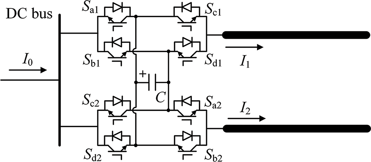
Figure 1: Topology schematic diagram of the interline dual H-bridge CFC
a) Capacitor bypass state (abbreviated as B): Sa OFF, Sb ON, Sc OFF, Sd ON or Sa ON, Sb OFF, Sc ON, Sd OFF.
b) Capacitor charge state (abbreviated as C): Sa ON, Sb OFF, Sc OFF, Sd ON.
c) Capacitor discharge state (abbreviated as D): Sa OFF, Sb ON, Sc ON, Sd OFF.
During the capacitor charge state, the H-bridge is equivalent to a positive voltage source inserted into the DC line; As for the capacitor discharge state, the H-bridge is equivalent to a negative voltage source inserted into the DC line; As for the capacitor bypass state, the H-bridge can be considered as short-circuited. Therefore, the current flow between the adjacent lines can be regulated by periodically controlling the insertion state of the capacitor. However, this CFC cannot satisfy the requirements of the multiterminal DC grid since it only has two ports. Therefore, it is expanded into the multiple H-bridge CFC in this part, whose topology is presented in Fig. 2.
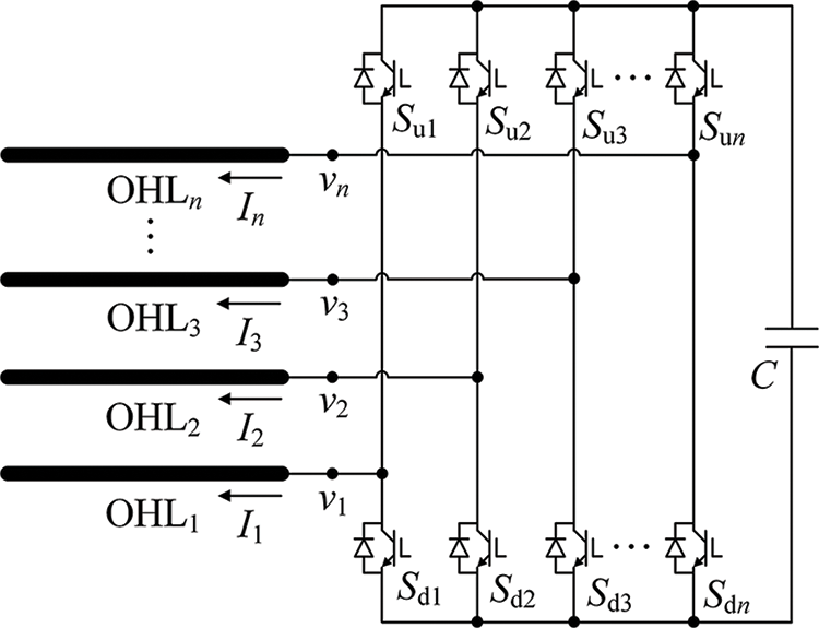
Figure 2: Topology schematic diagram of the multiple H-bridge CFC
The core principle of the multiple H-bridge CFC is the same as that of the interline dual H-bridge CFC. The corresponding relationship between the insertion states of the capacitor and the switch states of the H-bridge is listed in Table 1. The voltage drop across the energy storage capacitor is denoted by Uc (Uc > 0), and the DC line series voltage is represented by v1k.

The following example illustrates the core principle and control strategy of the multiple CFC. Considering that before the multiple CFC puts into operation, the DC line current satisfies I1 < 0 & I2,…, In > 0. In order to actively control the power flow distribution in the multiterminal DC grid, it is necessary to increase or decrease the current of some DC lines. As shown in Table 1, the switch state set (i, ii, iv) can make the energy storage capacitor to be discharged to increase the line current, and the state set (i, iii, iv) can make the energy storage capacitor to be charged to reduce the line current. Therefore, based on the above principle, the control strategy of the semiconductor switches in the multiple CFC is constructed in Fig. 3, in which the duty cycle Dsu1 is constant, and its value is set to 0.5 in this paper. The upper and lower bridge arm switches of the same port are in complementary operation state. The proportional integral (PI) control is utilized in Fig. 3. The trigger signal generated by the control system shown in Fig. 3 is presented in Fig. 4.
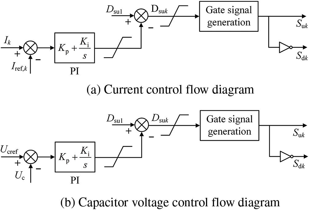
Figure 3: Control strategy of the multiple CFC
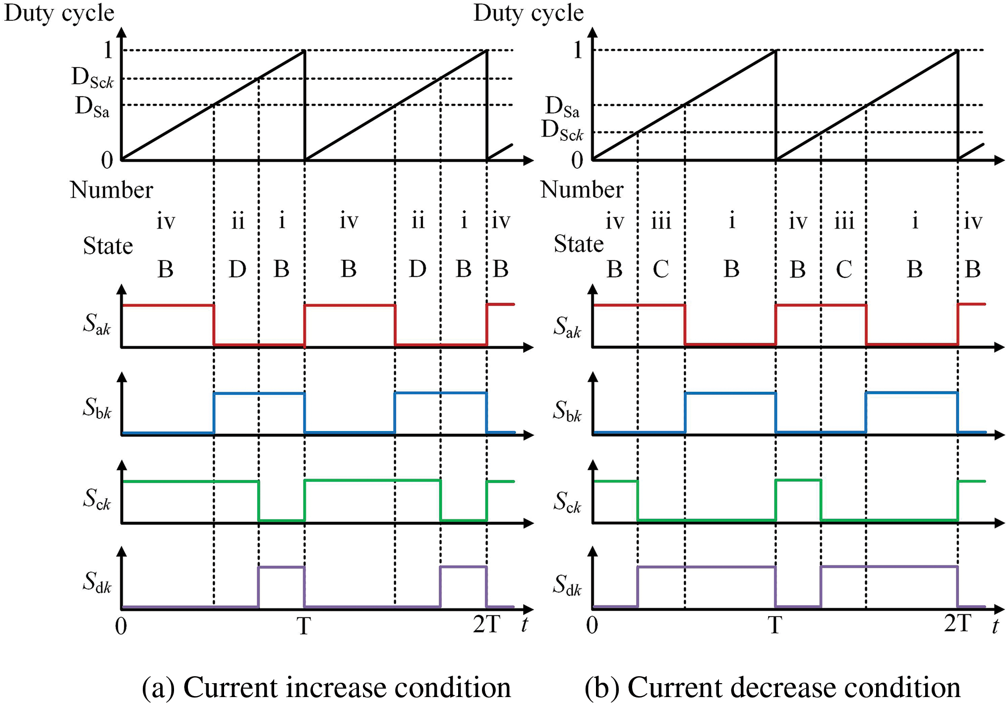
Figure 4: Trip signal of the multiple H-bridge CFC
In Fig. 3, it can be seen that: Once the actual line current Ik and the reference current Iref, k satisfy Ik < Iref, k or the actual energy storage capacitor voltage Uc and the reference voltage Ucref satisfy Uc > Ucref, the duty cycle of the switch Suk, S1k will satisfy Dsuk > Dsu1, corresponding to the switch condition in Fig. 4a. Under this condition, the energy storage capacitor will be discharged, and the line current will be increased, or the energy storage capacitor voltage will be reduced to follow the given reference value. Otherwise, the energy storage capacitor will be charged, and the line current will be decreased, or the energy storage capacitor voltage will be increased to follow the given reference value, corresponding to the switch state in Fig. 4b.
2.2 Topology and Operation Principles of DC Circuit Breaker
The DCCB topology is presented in Fig. 5. It has two branches, including the load current path and the main breaker (MB). The load current path is composed of a solid-state switch named as load commutation switch (LCS) and a mechanical switch named as ultrafast disconnector (UFD). The load current path should carry load current and commutate fault current after the occurrence of the fault. The MB is composed of two parts, the first part is all based on many fully controlled semiconductor switches, which should carry the fault current temporarily and force the fault current into the second part of the MB. The second part is all based on metal oxide varistors (MOVs), which should consume the fault current. The MB is the most expensive part in the DCCB. The DCCB takes the following steps to isolate the fault:

Figure 5: Topology of the DCCB
a) Assume that the fault occurs at the DC line connected to the DCCB. Therefore, the DCCB starts to isolate the fault.
b) By turning ON the MB and turning OFF the LCS, the fault current will be forced into the MB from the load current path, which leads to zero current in the UFD.
c) The UFD is commanded to open, and the UFD open time is always considered as 2 ms.
d) After the UFD is opened, the semiconductor switches in the MB should be turned OFF. After that, the fault current is forced into the MB and dissipated by the parallel MOVs.
e) After the fault current is interrupted by the MB, the RCB will totally isolate the fault.
3 Operation Principles of Integrated Equipment
Comparing the multiple H-bridge CFC in Fig. 2 with the DCCB in Fig. 5, the switch structure of multiple H-bridge CFC is similar to the LCS structure of DCCB, as shown in Fig. 6. Therefore, to reduce the configuration cost and operating loss of CFC and DCCB, the multiple H-bridge CFC and the DCCB can be combined into a single integrated equipment, as shown in Fig. 7. In addition to the fault isolation capability, the proposed integrated equipment not only has the ability of power flow control of adjacent lines, but also can isolate the fault rapidly. Compared with the separate configuration solution, the integrated equipment greatly reduces the manufacturing cost and operating loss, and improves the utilization efficiency of the semiconductor switches. The discharge resistor Rdc and the discharge switch Sdc in Fig. 7 are responsible for quickly discharging the energy storage capacitor. Since the discharge switch Sdc withstands a smaller voltage than the energy storage capacitor rated voltage, a fast mechanical switch or a semiconductor switch can be used. In addition, the MOV connected in parallel of the energy storage capacitor to prevent it from overvoltage and ensure its safe operation.
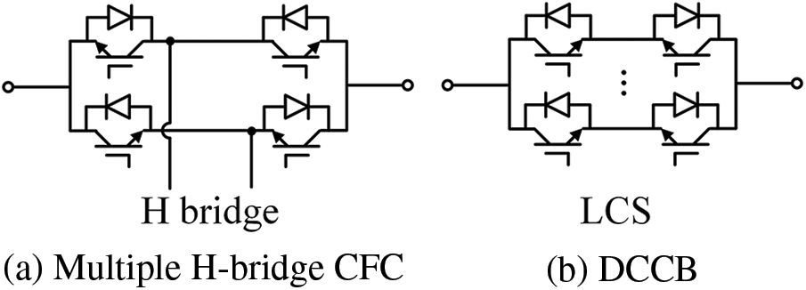
Figure 6: Structure comparison of multiple H-bridge CFC and DCCB
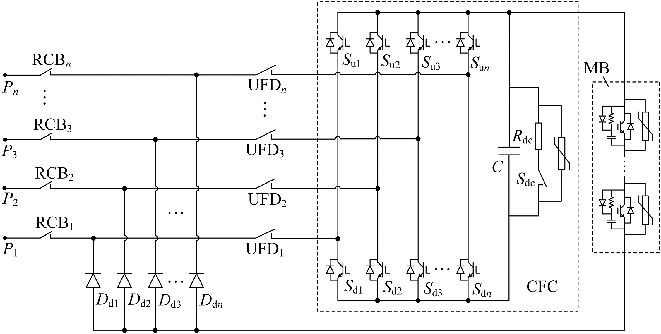
Figure 7: Topology of the integrated equipment
During the normal operation, if the multiterminal DC grid does not require the active regulation of power flow, the integrated equipment can be operated in bypass mode. The equivalent diagram of the integrated equipment in this mode is presented in Fig. 8. In Fig. 8, the following components are in the ON state: the semiconductor switches Suk, Sdk, the UFDs, the RCBs; the following components are in the OFF state: the switch Sdc, the MB.
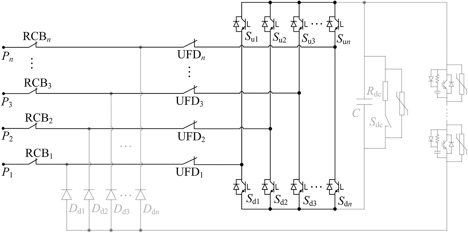
Figure 8: The integrated equipment operates in the bypass mode
3.2 Operation Sequences to Realize Current Flow Control
During the normal operation, after receiving the power flow control command, the integrated equipment will operate in the CFC inserted mode. In this mode, the flowing components are in the ON state: the UFDs, the RCBs; the following components are in the OFF state: the switch Sdc, the MB. In addition, the semiconductor switches Suk, Sdk will be turned ON and OFF periodically to realize the power flow control of adjacent lines. The control strategy has already been presented in Fig. 3. The equivalent diagram of the integrated equipment in this mode is shown in Fig. 9.
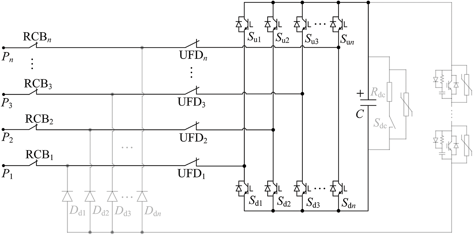
Figure 9: The integrated equipment operates in the CFC inserted mode
In this mode, if a healthy DC line needs to be cut OFF, the integrated equipment can control the current of the DC line to zero using the embedded CFC, and then the RCB on the DC line can be opened. Using this method to removal a heathy line can avoid the complex switching operation and the large voltage disturbance to the multiterminal DC grid if the DCCB is utilized.
3.3 Operation Sequences to Realize Fault Isolation
After a DC line fault occurs, the integrated equipment will operate to isolate the fault port, and it takes the following steps:
It is assumed that a fault occurs on the port P1 at time t0. After that, depending on the switch state of the fault occurrence moment, the fault current may have three paths in the integrated equipment:
a) Current path 1: Pk→UFDk→diode in Suk→insulated gate bipolar transistor (IGBT) in Su1→UFD1→RCB1→P1.
b) Current path 2: Pk→UFDk→IGBT in Sdk→diode in Sd1→UFD1→RCB1→P1.
c) Current path 3: Pk→UFDk→diode in Suk→capacitor C→diode in Sd1→UFD1→RCB1→P1.
After the integrated equipment receives the tripping command at time t1 and starts to isolate the fault port P1. Firstly, the MB is turned ON and the switch Su1 in the upper bridge arm of the fault port and the switches Sd1~Sdn in the lower bridge arms of all ports are turned OFF. After that, the fault current begins to be forced to the MB. Then, the UFD1 of the fault port starts to open. During the UFD operation period (t1 < t < t2), the status of each switch in the CFC-MPCB is shown in Fig. 10.
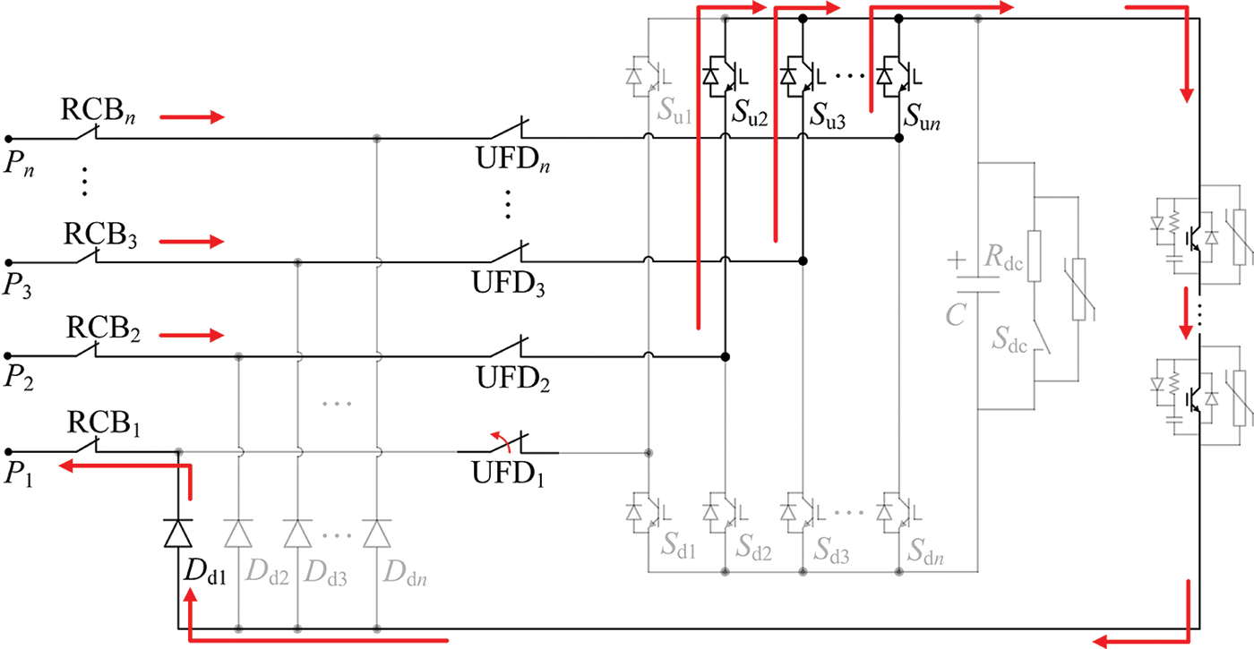
Figure 10: The equivalent diagram of the integrated equipment from time t1 to time t2
After the open process of the UFD, the MB is blocked to force the fault current to be consumed by the parallel MOVs. The MOVs will dissipate the fault current, as presented in Fig. 11. After the fault current is cleared at time t3, the RCB1 will isolate the fault line. In addition, refer to the operation status of the multiterminal DC grid, the integrated equipment can operate in the CFC inserted mode again to actively manage the load current of the remaining adjacent DC lines.
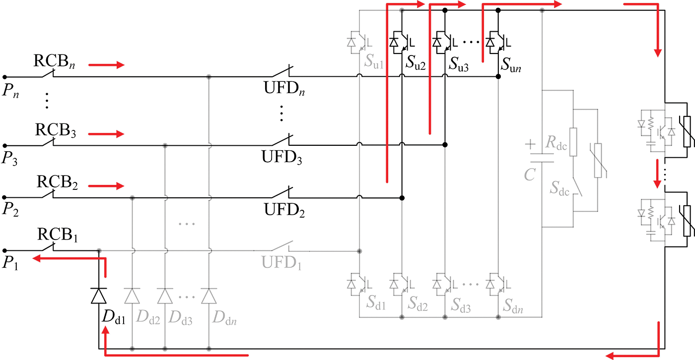
Figure 11: The equivalent circuit of the integrated equipment from time t2 to time t3
According to the above analysis, the fault isolation sequences of the integrated equipment are summarized in Fig. 12.
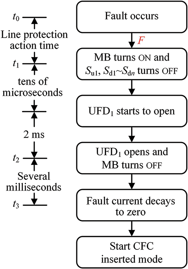
Figure 12: Fault isolation sequences of the integrated equipment
If the overhead line (OHL) is utilized in the multiterminal DC grid, the reclosing operation are demanded to try to shorten the power outage. When the reclosing of the fault line is implemented, to avoid the damage of the energy storage capacitor, it can be bypassed first. The reclosing process takes the following steps:
a) The switches Suk in the upper bridge arm of all healthy ports, the switches Sdk in the lower bridge arm of all non-fault ports are turned ON and turned OFF, respectively. After that, the energy storage capacitor is bypassed.
b) The MB is turned ON, and the fault property can be judged by the current magnitude flowing through the MB. When the MB current exceeds the threshold value, the permanent fault is determined, the MB is turned OFF again and RCB on the fault port is opened to isolate the fault line; otherwise, it is determined that a temporary fault has occurred, the switch Su1 is turned ON and the UFD on the fault port is closed. After the open process of the UFD, the MB is turned OFF again and the integrated equipment can operate in the CFC inserted mode again.
In order to examine the current flow control and fault isolation abilities of the integrated equipment, the simulation model of a specific meshed four-terminal DC grid is constructed in the PSCAD/EMTDC software, as presented in Fig. 13. The reason for choosing a meshed four-terminal DC grid is that only the multiterminal DC grid with a mesh structure has difficulty in controlling power flow. The modular multilevel converters (MMCs) with symmetrical monopole structure are configured, in which the converter S1 operates in constant voltage mode, and the converters S2~S4 operates in constant power mode. The DC line protection action time is 3 ms. The other parameters are listed in Table 2. In this part, both the power flow control and the fault isolation abilities of the integrated equipment are verified. The simulation results of current flow control and fault isolation are both shown in Figs. 14 and 15.
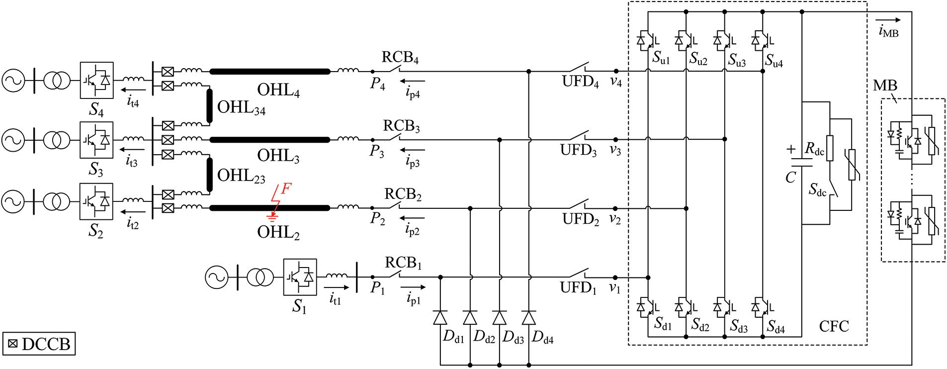
Figure 13: Topology of the simulation model

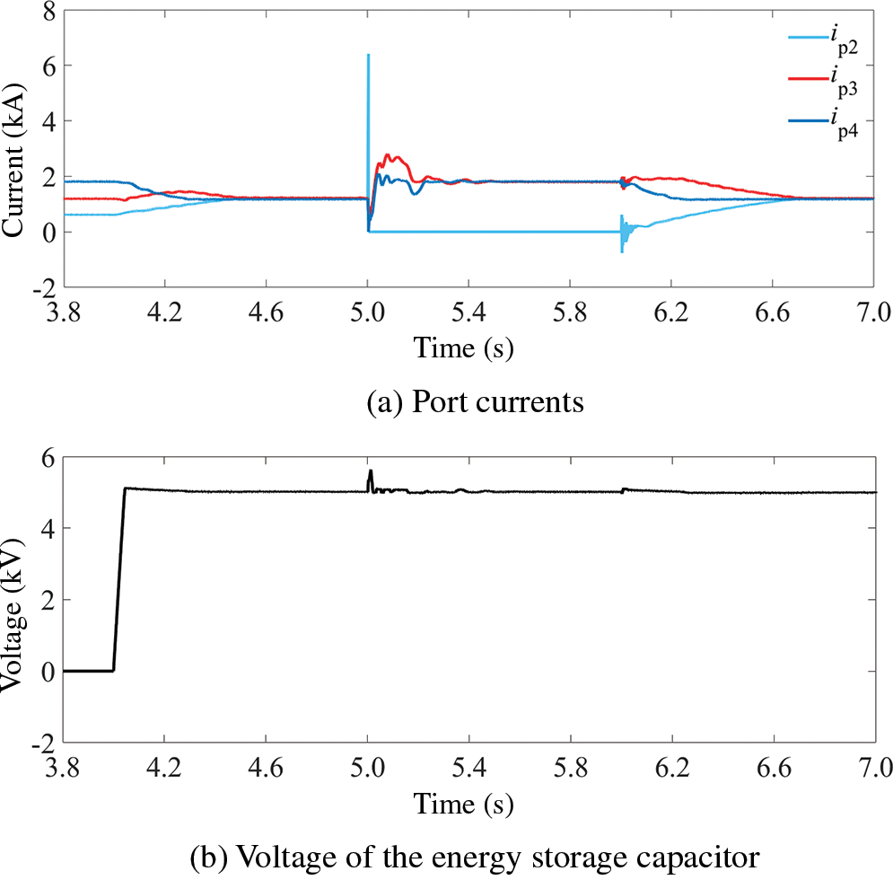
Figure 14: Simulation waveforms in the bypass mode
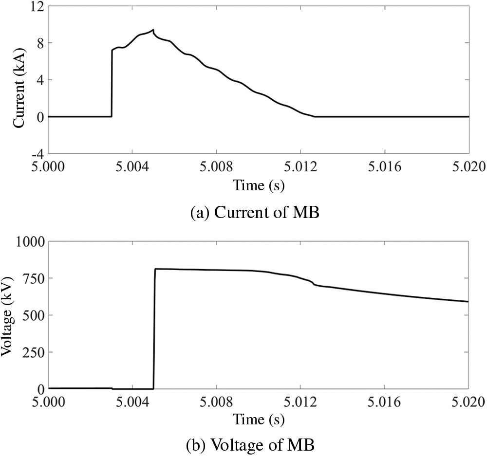
Figure 15: Simulation waveforms in the fault isolation
In the time period of t < 4.0 s, the integrated equipment operates in the bypass mode. In this mode, the power flows of all the lines are distributed based on the line resistances, as shown in Fig. 14a.
At 4.0 s, the integrated equipment starts to regulate the power flows of the connected lines according to the grid operation requirements. Assuming that the DC flow control target is the average current of each DC line, since the total value of the load current is 3.5 kA, the current reference values Iref, 2 and Iref, 3 of the ports P2, P3 are set to 1.17 kA, and the voltage reference value Ucref of port P4 is set to 5 kV. As shown in Fig. 14a, the line currents and the energy storage capacitor voltage reach the control target at about 4.45 s.
At 5.0 s, a fault F occurs on the DC line OHL2, and the fault duration is assumed to be 0.3 s. After that, the integrated equipment operates to isolate the fault port P2. When the fault current is commutated into the MOVs at 1.505 s, the fault current starts to decrease. Before this, the fault current still rises rapidly. During the fault current clearance process, the current peak of the MB is 7 kA. Besides, the diode branches of the non-fault ports and the MB will be subjected to the transient interruption voltage (the total residual voltage of MOVs, 800 kV) generated by the MOVs, as shown in Fig. 15. The MOV current consumption lasts about 5 ms, and the MOVs dissipate the energy of 11.71 MJ. After that, the fault line OHL2 can be completely isolated by RCB1. After that, the integrated equipment activates the power flow control function. At this time, the reference values Iref, 3, Ucref of the ports P3, P4 ports are set to 1.75 kA and 5 kV, respectively. The current of each line reaches the control target in about 5.5 s.
The integrated equipment starts to reclose at 6.0 s. After the DC line OHL2 is restored, the integrated equipment continues to manage the power flow of each DC line. The reference values Iref, 2, Iref, 3, and Ucref are set to 1.17 kA, 1.17 kA, and 5 kV, respectively. As shown in Fig. 14a, the current of each DC line reaches the reference value at 6.7 s.
This part will compare and analyze the manufacturing costs of the separate solution and the integrated solution of the CFC and DCCB to highlight the economic superiorities of the integrated equipment. Assume that the separate solution and the integrated equipment are respectively configured on a DC bus, and the DC bus has a total of n incoming and outgoing DC lines connected to it. Therefore, in order to achieve full selective removal of faults and power flow control of each DC line, if the separate solution is adopted, a total of n DCCBs and 1 multiple H-bridge CFC are required; while the integrated solution is adopted, only one n-port integrated equipment is required. Assuming that the rated voltage of the multiterminal DC grid is Udc, the peak voltage of the LCS in the DCCB during the fault isolation process is Um, the rated voltage of the energy storage capacitor in the integrated equipment is Urc. Then, the number and capacity of each component required for the two solutions are listed in Table 3. In Table 3, Uri and Urd are the rated voltages of the IGBT module and the diode, respectively, and Ek is the MOV capacity required to clear fault current on the kth DC line. In addition, to simplify the analysis, the current limitation and voltage margin of the semiconductor switches are not considered.

In Table 3, the number of UFDs required for the separate solution and the integrated solution is the same, but the separate solution requires 2n times the number of IGBT modules as the integrated solution. Since the IGBT modules is truly expensive the diodes, the cost of semiconductor switches in the separate solution is much higher than that of the integrated solution. In addition, since the DCCB on each line in the separate solution must have the ability to dissipate the fault current of this line, the total MOV capacity required for the separate solution is the sum of the MOV capacities on all lines, while the MOV capacity required for the integrated equipment is the maximum MOV capacity required to interrupt the faults of each line. Therefore, the MOV capacity required for the integrated equipment is much smaller than that of the separate solution. In summary, the integrated equipment has obvious advantages over the separate solution in terms of economy.
With regard to the integrated solution, the separate solution is equivalent to adding the conduction losses of n(Um + Urc)/Uri IGBT modules during normal operation. Therefore, the corresponding additional operating loss ΔPcl is n(Um + Urc)UCE/Uri, where UCE is the voltage drop when the IGBT conducts. Compared with the separate solution, the integrated equipment has lower operating losses, leading to higher grid operation efficiency. In addition, since the heat generated by the operating losses of semiconductor switches needs to be dissipated by a cooling system, the integrated solution can reduce the additional cost of the cooling system.
Compared to the traditional AC system, the multiterminal DC grid has more superiorities in integrating large-scale renewable energy. However, the multiterminal DC grid faces the challenges such as passive power flow control, vulnerability to DC line fault, etc., which significantly hinders its development. In this paper, the integrated equipment capable of controlling power flow and isolating DC-side fault is proposed to reduce the implementation costs, the power losses, and coordination control complexity of separate configurations of CFCs and DCCBs. The integrated equipment with n ports can be adopted to replace a n-port CFC and n DCCBs. Extensive simulations show that the integrated equipment is similar to the separate solution from the perspective of the DC grid, which means the integrated equipment can achieve the same functions for the multiterminal DC grid as separate solution with much lower costs and power losses.
Acknowledgement: The authors would like to thank Dr. Wei at Shandong University for his help in polishing this paper.
Funding Statement: This work was supported in part by Natural Science Foundation of Jiangsu Province under Grant BK20230255, and Natural Science Foundation of Shandong Province under Grant ZR2023QE281.
Author Contributions: The authors confirm contribution to the paper as follows: study conception and design: Shuo Zhang, Guibin Zou; data collection: Shuo Zhang; analysis and interpretation of results: Shuo Zhang; draft manuscript preparation: Shuo Zhang, Guibin Zou. All authors reviewed the results and approved the final version of the manuscript.
Availability of Data and Materials: Data available on request from the authors.
Ethics Approval: Not applicable.
Conflicts of Interest: The authors declare that they have no conflicts of interest to report regarding the present study.
References
1. H. Wang, X. Xu, G. Shen, and B. Jing, “Model predictive control strategy of multi-port interline DC power flow controller,” Energy Eng., vol. 120, no. 10, pp. 2251–2272, Sep. 2023. doi: 10.32604/ee.2023.028965. [Google Scholar] [CrossRef]
2. O. Gomis-Bellmunt, J. Sau-Bassols, E. Prieto-Araujo, and M. Cheah-Mane, “Flexible converters for meshed HVDC grids: From flexible AC transmission systems (FACTS) to flexible DC grids,” IEEE Trans. Power Del., vol. 35, no. 1, pp. 2–15, Feb. 2020. doi: 10.1109/TPWRD.2019.2939588. [Google Scholar] [CrossRef]
3. P. Han, X. Zhao, Y. Wu, Z. Zhou, and Q. Qi, “Adaptive reclosing scheme based on traveling wave injection for multi-terminal dc grids,” Energy Eng., vol. 120, no. 5, pp. 1271–1285, Feb. 2023. doi: 10.32604/ee.2023.027489. [Google Scholar] [CrossRef]
4. W. Wen, H. Jin, B. Li, P. Li, H. Liu and B. Li, “Breaking current balance enhancement for parallel IGBT modules in DC circuit breaker,” IEEE Trans. Power Elect., vol. 38, no. 12, pp. 15433–15441, Dec. 2023. doi: 10.1109/TPEL.2023.3315270. [Google Scholar] [CrossRef]
5. R. Li, L. Xu, D. Holliday, F. Page, S. J. Finney and B. W. Williams, “Continuous operation of radial multiterminal HVDC systems under DC fault,” IEEE Trans. Power Del., vol. 31, no. 1, pp. 351–361, Feb. 2016. doi: 10.1109/TPWRD.2015.2471089. [Google Scholar] [CrossRef]
6. J. He, Y. Sheng, B. Li, Y. Li, and B. Zhou, “A novel segmented-COV-based single-ended line protection algorithm for the multiterminal MMC-HVDC system with no boundary reactor,” IEEE Trans. Ind. Inf., vol. 20, no. 4, pp. 5658–5670, Apr. 2024. doi: 10.1109/TII.2023.3331523. [Google Scholar] [CrossRef]
7. L. Liu, A. Lekić, and M. Popov, “Robust traveling wave-based protection scheme for multiterminal DC grids,” IEEE Trans. Power Del., vol. 38, no. 5, pp. 3117–3129, Oct. 2023. doi: 10.1109/TPWRD.2023.3265748. [Google Scholar] [CrossRef]
8. J. He et al., “A passive thyristor-based hybrid DC circuit breaker,” IEEE Trans. Power Elect., vol. 38, no. 2, pp. 1791–1805, Feb. 2023. doi: 10.1109/TPEL.2022.3214864. [Google Scholar] [CrossRef]
9. S. Zhang, G. Zou, F. Gao, X. Wei, and C. Zhou, “A comprehensive review of multiport DC circuit breakers for MTdc grid protection,” IEEE Trans. Power Elect., vol. 38, no. 7, pp. 9100–9115, Jul. 2023. doi: 10.1109/TPEL.2023.3264534. [Google Scholar] [CrossRef]
10. F. Mohammadi et al., “HVDC circuit breakers: A comprehensive review,” IEEE Trans. Power Elec., vol. 36, no. 12, pp. 13726–13739, Dec. 2021. doi: 10.1109/TPEL.2021.3073895. [Google Scholar] [CrossRef]
11. M. Bröker and V. Hinrichsen, “Testing metal oxide varistors for HVDC breaker application,” IEEE Trans. Power Del., vol. 34, no. 1, pp. 346–352, Feb. 2019. doi: 10.1109/TPWRD.2018.2877464. [Google Scholar] [CrossRef]
12. J. Liao, N. Zhou, Z. Qin, P. Purgat, Q. Wang and P. Bauer, “Coordination control of power flow controller and hybrid DC circuit breaker in MVDC distribution networks,” J. Modern Power Syst. Clean Energy, vol. 9, no. 6, pp. 1257–1268, Nov. 2021. doi: 10.35833/MPCE.2021.000299. [Google Scholar] [CrossRef]
13. X. Zhong, M. Zhu, Y. Chi, S. Liu, and X. Cai, “Composite DC power flow controller,” IEEE Trans. Power Electron, vol. 35, no. 4, pp. 3530–3542, Apr. 2020. doi: 10.1109/TPEL.2019.2936773. [Google Scholar] [CrossRef]
14. Q. Mu, J. Liang, Y. Li, and X. Zhou, “Power flow control devices in DC grids,” in Proc. 2012 IEEE Power Energy Soc. Gen. Meet., San Diego, CA, USA, 2012, pp. 1–7. doi: 10.1109/pesgm.2012.6345674. [Google Scholar] [CrossRef]
15. E. Veilleux and B. T. Ooi, “Multiterminal HVDC with thyristor power-flow controller,” IEEE Trans. Power Del., vol. 27, no. 3, pp. 1205–1212, Jul. 2012. doi: 10.1109/TPWRD.2012.2187463. [Google Scholar] [CrossRef]
16. L. Z. Yao, H. F. Cui, J. Zhuang, G. J. Li, B. Yang and Z. B. Wang, “A DC power flow controller and its control strategy in the DC grid,” in Proc. 2016 IEEE 8th Int. Power Elect. Motion Control Conf., Hefei, China, 2016, pp. 2609–2614. doi: 10.1109/IPEMC.2016.7512709. [Google Scholar] [CrossRef]
17. N. Deng, P. Wang, X. P. Zhang, G. Tang, and J. Cao, “A DC current flow controller for meshed modular multilevel converter multiterminal HVDC grids,” CSEE J. Power Energy Syst., vol. 1, no. 1, pp. 43–51, Mar. 2015. doi: 10.17775/CSEEJPES.2015.00006. [Google Scholar] [CrossRef]
18. J. Sau-Bassols, E. Prieto-Araujo, and O. Gomis-Bellmunt, “Modelling and control of an interline current flow controller for meshed HVDC grids,” IEEE Trans. Power Del., vol. 32, no. 1, pp. 11–22, Feb. 2017. doi: 10.1109/TPWRD.2015.2513160. [Google Scholar] [CrossRef]
19. X. Zhang, J. Jin, Y. Ye, and X. Yang, “Analysis of a series-parallel-connected type DC power flow controller in multiterminal grids,” IEEE Trans. Power Elect., vol. 37, no. 6, pp. 7400–7410, Jun. 2022. doi: 10.1109/TPEL.2021.3139378. [Google Scholar] [CrossRef]
20. S. Wang, C. Li, O. D. Adeuyi, G. Li, C. E. Ugalde-Loo and J. Liang, “Coordination of MMCs with hybrid DC circuit breakers for HVDC grid protection,” IEEE Trans. Power Deliv., vol. 34, no. 1, pp. 11–22, Feb. 2019. doi: 10.1109/TPWRD.2018.2828705. [Google Scholar] [CrossRef]
21. W. Liu, C. Li, C. E. Ugalde-Loo, S. Wang, G. Li and J. Liang, “Operation and control of an HVDC circuit breaker with current flow control capability,” IEEE J. Emerg. Sel. Top. Power Elect., vol. 9, no. 4, pp. 4447–4458, Aug. 2021. doi: 10.1109/JESTPE.2020.3005894. [Google Scholar] [CrossRef]
22. J. Xu, X. li, G. Li, and C. Zhao, “DC current flow controller with fault current limiting and interrupting capabilities,” IEEE Trans. Power Deliv., vol. 36, no. 5, pp. 2606–2614, Oct. 2021. doi: 10.1109/TPWRD.2020.3023113. [Google Scholar] [CrossRef]
23. H. R. A. Mohamed and Y. A. -R. I. Mohamed, “Assessment and mitigation of DC breaker impacts on VSC-MTDC grid equipped with power flow controller,” IEEE Open J. Power Elect., vol. 4, pp. 237–251, 2023. doi: 10.1109/OJPEL.2023.3249682. [Google Scholar] [CrossRef]
24. S. Balasubramaniam, C. E. Ugalde-Loo, J. Liang, T. Joseph, R. King and A. Adamczyk, “Experimental validation of dual H-bridge current flow controllers for meshed HVdc grids,” IEEE Trans. Power Deliv., vol. 33, no. 1, pp. 381–392, Feb. 2018. doi: 10.1109/TPWRD.2017.2752301. [Google Scholar] [CrossRef]
Cite This Article
 Copyright © 2025 The Author(s). Published by Tech Science Press.
This work is licensed under a Creative Commons Attribution 4.0 International License , which permits unrestricted use, distribution, and reproduction in any medium, provided the original work is properly cited.


 Submit a Paper
 Propose a Special lssue
 View Full Text
 Download PDF
 Downloads
 Citation Tools