 Open Access
ARTICLE
Modeling and Capacity Configuration Optimization of CRH5 EMU On-Board Energy Storage System
School of Automation and Electrical Engineering, Lanzhou Jiaotong University, Lanzhou, 730070, China
* Corresponding Author: Mingxing Tian. Email:
Energy Engineering 2025, 122(1), 307-329. https://doi.org/10.32604/ee.2024.057426
Received 17 August 2024; Accepted 26 September 2024; Issue published 27 December 2024
Abstract
In the context of the “dual carbon” goals, to address issues such as high energy consumption, high costs, and low power quality in the rapid development of electrified railways, this study focused on the China Railways High-Speed 5 Electric Multiple Unit and proposed a mathematical model and capacity optimization method for an on-board energy storage system using lithium batteries and supercapacitors as storage media. Firstly, considering the electrical characteristics, weight, and volume of the storage media, a mathematical model of the energy storage system was established. Secondly, to tackle problems related to energy consumption and power quality, an energy management strategy was proposed that comprehensively considers peak shaving and valley filling and power quality by controlling the charge/discharge thresholds of the storage system. The capacity optimization adopted a bi-level programming model, with the series/parallel number of storage modules as variables, considering constraints imposed by the Direct Current to Direct Current converter, train load, and space. An improved Particle Swarm Optimization algorithm and linear programming solver were used to solve specific cases. The results show that the proposed onboard energy storage system can effectively achieve energy savings, reduce consumption, and improve power quality while meeting the load and space limitations of the train.Keywords
Abbreviations
| CRH5 | China Railways High-Speed 5 |
| DC | Direct Current |
| DC/DC | Direct Current to Direct Current |
| AC/DC | Alternating Current to Direct Current |
| DC/AC | Direct Current to Alternating Current |
| OESS | On-Board Energy Storage System |
| SOC | State of Charge |
| DOD | Depth of Discharge |
| RBE | Regenerative Braking Energy |
| PSO | Particle Swarm Optimization |
| EMU | Electric Multiple Unit |
| CPLEX | Mixed-Integer Linear Programming Solver |
| THDi | Total Harmonic Current Distortion |
| KKT | Karush-Kuhn-Tucker |
As of the end of 2021, the total annual electricity consumption of the national railway reached 7.87 × 10¹⁰ kWh, making electrified railways one of the highest energy-consuming end users in the power grid. From the perspective of the entire lifecycle energy consumption, electrified railways remain a key area for carbon emissions [1].
The electricity cost for electrified railways is usually calculated based on a two-part tariff: one part is the basic electricity fee, determined by transformer capacity and maximum load demand; the other is the energy fee, directly linked to actual electricity consumption. Since these fees are directly affected by peak traction load, taking appropriate load peak shaving measures can effectively reduce both parts of the electricity cost. Additionally, the regenerative braking power generated during the braking process of the Electric Multiple Unit (EMU) or electric locomotives, if not promptly absorbed, may affect the power quality of the traction network [2]. The key indicator for measuring power quality is the Total Harmonic Current Distortion (THDi), which is closely related to the train’s traction power and regenerative braking power [3]. Therefore, rational utilization of regenerative braking power can not only effectively reduce electricity costs but also improve power quality.
The On-Board Energy Storage System (OESS) in electrified railways plays a crucial role in the aforementioned areas, including but not limited to (1) regenerative braking power recovery: energy generated during train braking can be captured and stored by the OESS, reducing energy waste; (2) peak shaving and valley filling: during peak load periods, the OESS can discharge stored energy to reduce the strain on the traction network, while during off-peak times, it can store excess energy [4]; (3) enhancing traction network stability: by regulating the charging and discharging processes, OESS can mitigate load fluctuations, improving the overall stability and reliability of the traction network; (4) supporting renewable energy integration: OESS can be paired with renewable sources like solar and wind power to enhance their efficiency [5]. OESS employs various energy storage technologies, such as supercapacitors, flywheels, and lithium batteries, each with distinct characteristics. For example, supercapacitors offer high-power-density and a long lifespan but lower energy density [6,7]; flywheel systems provide rapid charge and discharge capabilities, making them suitable for short-term, high-power output [8]; and lithium batteries offer high-energy-density, making them ideal for long-term energy storage [9].
Significant progress has been made in research on OESS applications, particularly in energy management strategies. Recent studies have integrated lithium batteries and supercapacitors as auxiliary power sources for trams powered primarily by fuel cells. By optimizing the series/parallel configurations of these energy storage systems and preventing overcharging and over-discharging, the power output of the auxiliary systems has been optimized, effectively reducing the load on the fuel cells [10]. Research on the impact of the weight of OESS on economics has similarly used the series/parallel number of energy storage modules as optimization variables to obtain the minimum weight and most economical energy storage system capacity configuration [11]. However, these studies did not consider the relationship between the series/parallel number of energy storage modules and the electrical characteristics of the energy storage media. Particularly, the lack of reasonable constraints on the series/parallel number of energy storage modules can cause the voltage applied by the Direct Current to Direct Current (DC/DC) converter to individual cells to exceed the maximum charging voltage, posing safety risks.
In terms of ground-based energy storage systems [12], which are similar to OESS, studies have constructed a bi-level programming model considering demand management to address the difficulty of separating energy storage configuration and scheduling operations, solving different time-scale problems in layers [13]. However, the cost and benefit models established in these studies are not sufficiently comprehensive for evaluating the overall value of energy storage systems. To solve the nonlinear complementarity slackness conditions that may be included in the bi-level model, researchers have used Karush-Kuhn-Tucker (KKT) conditions and linearization methods to transform the bi-level model into a single-layer mixed-integer linear optimization model for solution [14]. Regarding the power distribution of different energy storage media in energy storage systems, studies have allocated the total power of the energy storage system through Fourier decomposition or used a State of Charge (SOC) model to find the optimal economic power distribution scheme by optimizing the charge/discharge threshold and energy storage capacity configuration parameters [15]. However, these studies neglected the impact of frequent charge and discharge of the energy storage system on the power quality of the traction network and did not consider the weight and volume limitations of the energy storage modules. In contrast, OESS must prioritize meeting the stringent weight and volume restrictions of trains, a key difference from ground-based energy storage systems. Moreover, OESS has advantages in handling harmonic currents that ground-based systems cannot replace [16]. Additionally, research on the capacity configuration of high-speed EMU OESS is limited.
To address these shortcomings, this paper proposes a mathematical model for the OESS that considers the electrical characteristics, weight, and volume of the energy storage media. It constructs a bi-level programming model with the series/parallel number of energy storage modules as decision variables, considering the constraints of DC/DC converters and train load space. The upper level of the model uses an improved Particle Swarm Optimization (PSO), and the lower level uses a Mixed-Integer Linear Programming Solver (CPLEX). The energy management strategy comprehensively considers peak shaving valley filling and power quality. The proposed model and strategy have been verified through case studies to show significant energy-saving and power quality improvement effects.
Due to the characteristics of traction loads, which simultaneously have high energy and high power demands [17], the OESS adopts a hybrid energy storage system composed of high-energy-density lithium batteries and high-power-density supercapacitors to meet the needs of the traction load. The structure of the OESS is shown in Fig. 1.
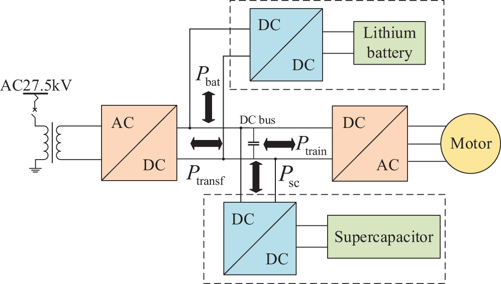
Figure 1: The structure of the OESS
In studying the power flow within the EMU, particularly in the OESS, the voltage at the pantograph is assumed to remain constant regardless of the EMU’s position, simplifying the analysis. The energy storage device is connected to the Direct Current (DC) bus of the converter through a DC/DC converter, which controls the energy storage device to achieve the function of peak shaving and valley filling. When the power flow from the Alternating Current to Direct Current (AC/DC) converter to the Direct Current to Alternating Current (DC/AC) converter is defined as the positive direction, the power relationship on the DC bus is shown in Eq. (1):
where
Among them,
where
where
3 Energy Management Strategy for OESS
Although ground-based energy storage systems are equipped with Railway Power Conditioner (RPC) to handle harmonic currents, their installation location, being far from the harmonic source, prevents them from addressing harmonics at the point of generation [18–20]. This results in harmonic currents circulating in the traction network, thereby affecting the power quality of the traction network. In contrast, OESS, being closer to the harmonic source of the traction load—the traction rectifier, can control the charging/discharging process through an energy management strategy. This allows direct adjustment of the power on the secondary side of the main transformer and reduces the regenerative braking power fed back to the traction network, indirectly improving the power quality on the network side.
To achieve the above objectives, the energy management strategy aims for optimal system economy while considering power quality. It employs an optimization algorithm to control the discharge threshold (
1) Function of Lithium Batteries: Leveraging their high-energy-density, lithium batteries are used to mitigate large amplitude, and slower fluctuations in load during peak and valley intervals. During peak load periods, the batteries discharge energy to meet increased demand; during off-peak periods, they store surplus energy for future use.
2) Function of Supercapacitors: Capitalizing on their high-power-density and extended cycle life, supercapacitors are employed to manage smaller amplitude, and rapid fluctuations in load. They quickly respond to short-term load changes, either supplying or absorbing additional power, while maintaining high efficiency and durability through frequent charge-discharge cycles.
This strategy aims to achieve two key objectives: minimizing the regenerative braking power returned to the traction network and selectively reducing peak traction power.
Fig. 2 illustrates the schematic diagram of peak shaving and valley filling of OESS. In the figure: the
1) Region 1:
2) Region 2:
3) Region 3:
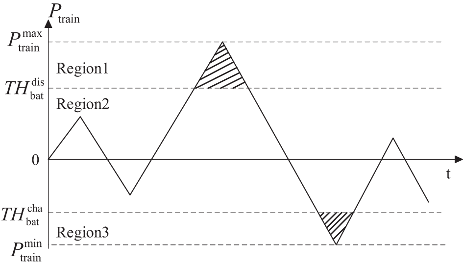
Figure 2: Schematic diagram of peak shaving and valley filling of OESS
4 Mathematical Model of the OESS
Due to the very limited load and space of the train, the primary consideration when designing an OESS is its weight and volume. Calculating the weight and volume of the energy storage system requires determining the number of series and parallel connections of the energy storage modules, which are influenced by the electrical characteristics of the energy storage medium as well as the voltage and current of the DC/DC converter.
For example, for lithium batteries, the safe operating voltage range of the battery is limited by the maximum charging voltage and the minimum protection voltage. To ensure the battery operates safely and stably, the average voltage applied to a single battery cell by the DC/DC converter must be within this range. Meanwhile, the output voltage of the battery pack depends on the number of cells connected in series, and the output current depends on the number of cells connected in parallel. Therefore, the voltage and current constraints of the DC/DC converter directly affect the number of series and parallel connections in the battery pack, ensuring the battery’s safe operation and charging status. Additionally, current constraints prevent the DC/DC converter from being damaged by the high currents that could occur when battery packs are connected in parallel.
To meet these requirements, a mathematical model of OESS was established with the number of series and parallel connections of the energy storage modules as variables.
4.1 Mathematical Model of Lithium Battery Pack
The actual output power and actual output energy of a single battery cell can be calculated using the Eq. (4):
where
The mathematical model for the lithium battery pack is Eq. (5):
where
The SOC calculation of the lithium battery pack is shown in Eq. (6):
where
4.2 Mathematical Model of Supercapacitor Group
The maximum output power and usable effective energy of a single supercapacitor can be calculated using the Eq. (7):
where
The mathematical model for the supercapacitor bank is Eq. (8):
where
The SOC calculation of supercapacitor group is shown in Eq. (9):
where
5 Bi-Level Programming Model and Its Solving Algorithm
Due to the non-linearity of the rated power and rated energy caused by the product of the series/parallel configuration of the storage modules, these parameters cannot be directly used as constraints in the CPLEX solver. To overcome this challenge, a bi-level programming model is employed. In the upper layer, an algorithm optimizes the series/parallel configuration of the storage modules to obtain constant values. Subsequently, in the lower layer, CPLEX can process these rated power and rated energy as linear constraints.
In power system applications, when the upper-layer and lower-layer problems each possess convex, continuously differentiable properties, optimality conditions are satisfied, and optimal solutions exist. The linear programming used here is a common convex optimization problem, and thus naturally has optimal solutions.
The upper layer model aims to maximize annual net revenue, calculated based on the annual revenue from the demand side of the storage system and the full life cycle cost of the storage system. The objective function is shown in Eq. (10):
where
Define
where
5.1.1 Full Life Cycle Cost Model
1) The annual purchase cost of supercapacitors is depicted in Eq. (12):
where
2) The annual purchase cost of lithium batteries is depicted in Eq. (13):
where
3) Annual purchase cost of system supporting equipment is depicted in Eq. (14):
Includes the purchase cost of the on-board DC/DC converters, and modification costs for the train or trailer.
where
4) The annual maintenance cost of lithium batteries is depicted in Eq. (15):
where
5) Replacement cost of lithium batteries is depicted in Eq. (16):
Replacement costs of lithium batteries decrease gradually over the system’s life cycle [19]:
where
6) Reduced passenger revenue due to the weight of the storage modules is depicted in Eq. (17):
The installation of the storage system reduces available train space, leading to fewer passengers and affecting the railway department’s revenue. Therefore, reduced passenger revenue should be included in the cost of the storage system:
where
7) Annual recycling cost of lithium batteries (residual value of equipment) is depicted in Eq. (18):
Retired batteries can typically be used in other applications with lower performance requirements:
where
5.1.2 Demand-Side Revenue Model
The demand-side revenue consists of direct and indirect benefits. Direct benefits refer to the revenue generated from the peak shaving and valley filling achieved by the OESS. Indirect benefits refer to the potential savings and optimizations in the traction substation and its transmission and distribution lines over the entire life cycle of the storage system.
1) Direct benefits:
Due to the policy of “negative feed-in metering” for regenerative braking power, using the energy storage system to absorb part of the regenerative braking power reduces the power fed back to the traction network, thus achieving valley filling. The direct benefit is given by Eqs. (19) and (20):
where
2) Indirect benefits:
The OESS installed in the EMU acts as a mobile energy storage station, positively impacting the operation of the traction network through its long-term charge-discharge cycles. Specifically, this application can reduce the maximum demand for the traction substation and decrease the need for new or expanded traction substations, transformers, transmission lines, and associated equipment. This brings optimization potential for the railway system’s infrastructure investment.
The indirect benefit is given by Eq. (21):
where
where
The lower layer model aims to minimize the operating electricity cost within the sampling time after the installation of the energy storage system on the EMU. The objective function is given by Eq. (25):
1) Electricity cost is depicted in Eq. (26):
where
2) Basic electricity fee is depicted in Eq. (27):
The basic electricity fee is calculated based on the maximum demand of the month, reflecting the peak power of the traction load.
where
3) Additional electricity fee is depicted in Eq. (28):
where
The constraints for OESS are more stringent than those for ground-based energy storage systems. These include not only power and SOC constraints but also train load and space constraints, as well as DC/DC converter constraints.
1) Electric power balance constraints is depicted in Eq. (29):
2) Constraints for lithium battery packs is depicted in Eq. (30):
where
3) Constraints for supercapacitor groups is depicted in Eq. (31):
where
4) Voltage and current constraints for DC/DC converters is depicted in Eq. (32):
where
5) Constraints on EMU load and space:
Unlike ground-based energy storage systems, the number of energy storage modules in OESS is strictly limited by the train’s load and space. This constraint is added to the upper-level objective function as a penalty function
The train load and available space are given by Eq. (33):
where
From Eq. (33), the train load space constraint is depicted in Eq. (34):
5.4 Bi-Level Programming Model Solving Algorithm
To address the limitation that CPLEX can only use linear constraints, this paper combines the PSO with CPLEX for model solving.
To overcome the shortcomings of traditional PSO, such as its tendency to get trapped in local optima and its slow convergence speed, this paper employs an improved PSO with linearly decreasing inertia weight
where
As the number of iterations increases, the inertia weight gradually decreases, thereby enabling the PSO to have strong global convergence capabilities in the initial phase and strong local convergence capabilities in the later stages.
where
The initial value of
The upper layer uses the improved PSO to maximize the annual net revenue of the energy storage system by optimizing the series/parallel number of energy storage modules and the charge/discharge threshold of the lithium batteries. The lower layer uses CPLEX to optimize the output power of the energy storage system to minimize the operating electricity cost of the train within the sampling time. The specific steps are as follows:
1) Algorithm Initialization: Read the load curve, energy storage technical indicators, energy storage costs, and electricity prices.
2) Random Generation: Generate random positions and velocities for particles in the population that meet constraints, thus determining the series/parallel number of energy storage modules and the charge/discharge threshold of the lithium batteries for the current iteration.
3) Conversion: Convert the series/parallel number of energy storage modules into rated power, rated energy, volume, and weight variables for the current iteration according to Eqs. (4)–(9), and pass them to the lower model.
4) CPLEX Optimization: Call CPLEX to solve the lower model to obtain the output power of the energy storage system for the current iteration and pass the results to the upper model.
5) Fitness Calculation: Calculate the fitness value of individuals in the population based on rated power, rated energy, volume, weight, and output power of the energy storage modules. If there are individuals with a large fitness value that do not meet the train constraints, add a penalty function
a) When the total weight of the lithium batteries and supercapacitors (
This penalty causes the outer objective function, or fitness function, to decrease sharply, reducing the net benefit to a very small value. In the PSO algorithm, this leads to the rejection of the current lithium battery and supercapacitor configuration in the iteration.
For example, if 3000 lithium batteries and 200 supercapacitors are used, the total weight (
b) When the total weight (
In this scenario, the penalty function does not influence the fitness function, indicating that the configuration satisfies the weight and volume constraints in the current iteration. This approach ensures that the algorithm automatically excludes configurations that exceed the weight and volume limits while retaining those that meet the constraints, thereby guiding the PSO toward finding the optimal solution.
6) Update Global and Individual Extremes: Update the global and individual extremes based on fitness, and update the particles’ positions and velocities. Repeat Steps 3) to 6) until the termination condition is met.
The bi-level programming model structure for the capacity configuration of the OESS is shown in Fig. 3.
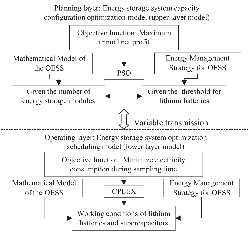
Figure 3: The bi-level programming model structure for the capacity configuration of the OESS
In this study, we used the load data from a CRH5 EMU operating on a mountainous route with significant gradients. The total length of the route is 677 km, and the train’s running time is 3 h and 12 min. The geographic information is shown in Fig. 4, the load data is presented in Fig. 5 and the EMU details are provided in Table 1. The lifespan of the energy storage system is assumed to be 10 years, with a discount rate of 8% and a sampling interval of 1 min.
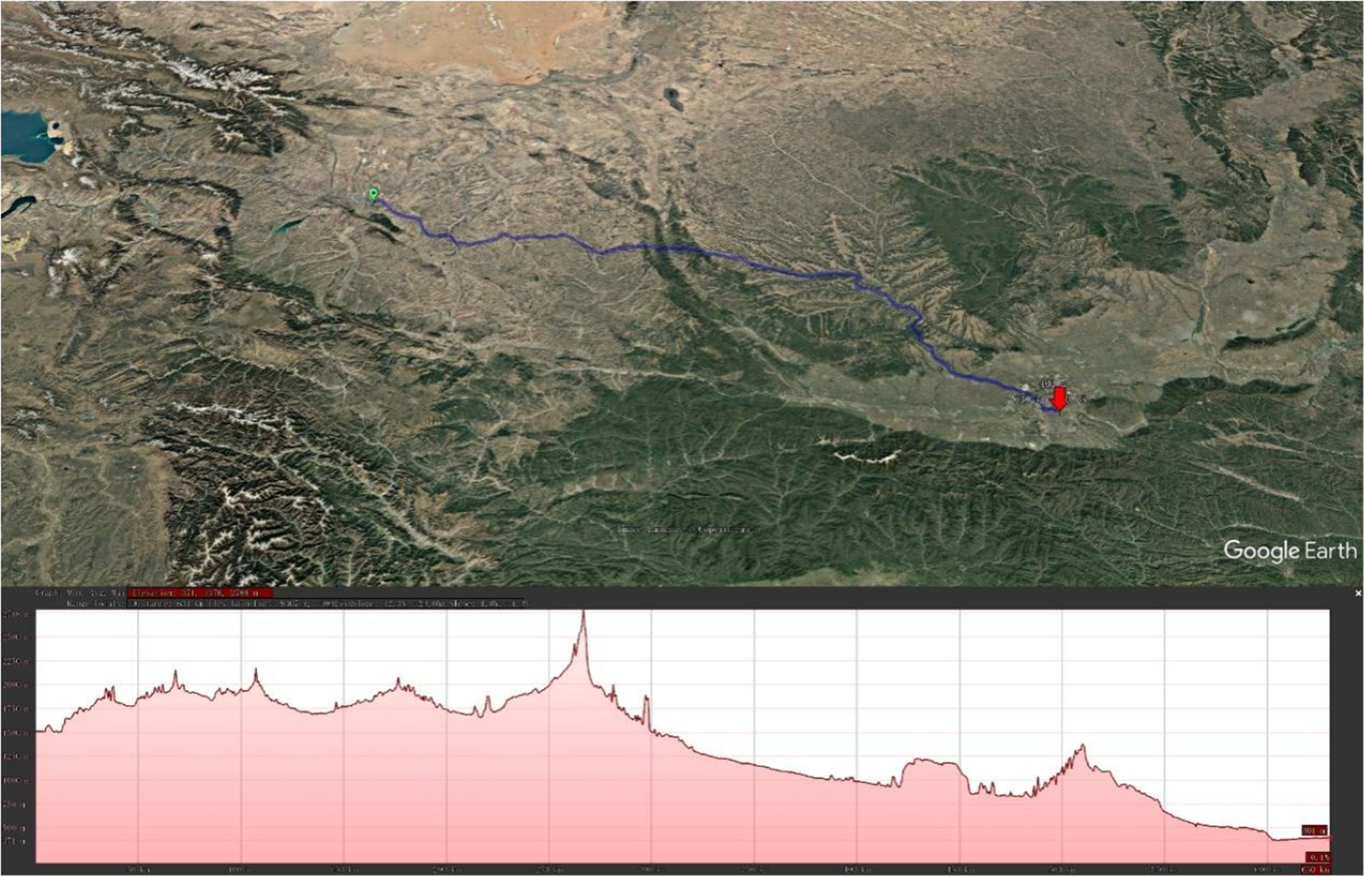
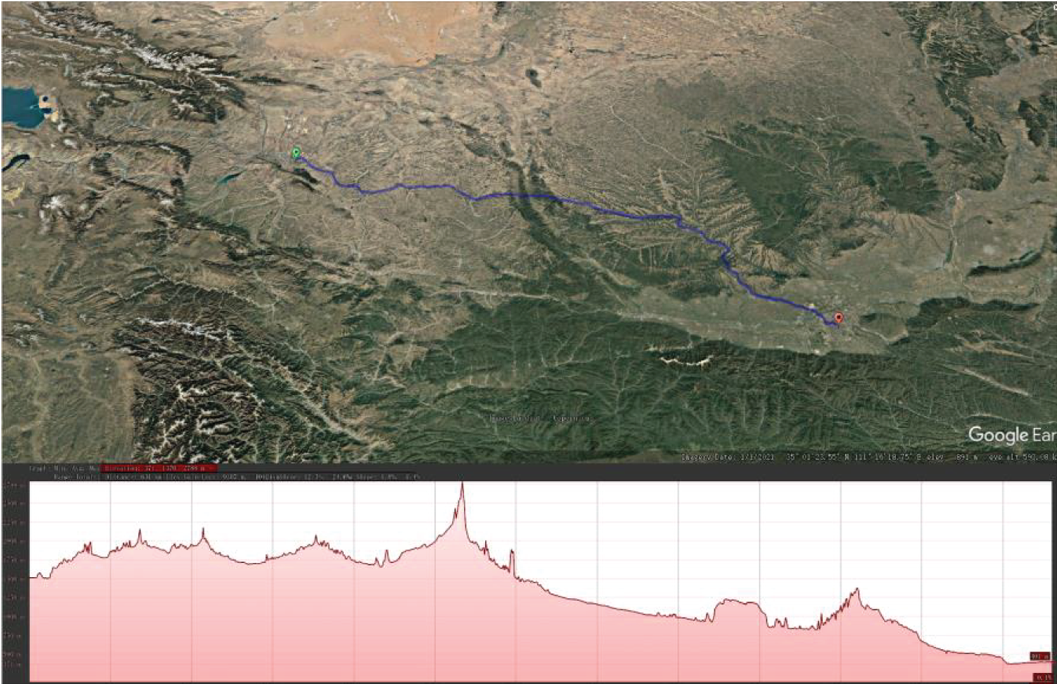
Figure 4: Geographic information
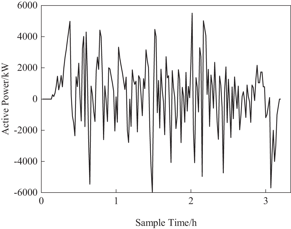
Figure 5: Load data of CRH5 EMU

We utilized BYD’s lithium iron phosphate blade batteries (with a cycle life of over 3000 cycles) and Maxwell’s BMOD0165 supercapacitors (with an expected lifespan of 10 years under normal temperature conditions). Their basic parameters are listed in Table 2. Combined with our energy management strategy, the expected lifespan of the lithium batteries is projected to be 5 years, which aligns with BYD’s experience in the rail transit sector.

6.2 Simulation Result Analysis
6.2.1 Optimize Configuration Results
The optimization results of the OESS are shown in Table 3. The average voltage of the supercapacitors is greater than the minimum working voltage and less than the rated voltage. Similarly, the average voltage of the lithium batteries is greater than the minimum protection voltage and less than the maximum charging voltage. The series/parallel numbers of the energy storage modules satisfy the voltage and current constraints of the DC/DC converters, ensuring that the modules can be fully charged and operate within the safe range. The total weight and volume of the energy storage modules are 10.53 tons and 5436.3 liters, respectively, which are within the allowable limits for train load and space. The net profit of the energy storage system over its entire lifecycle is 7.296 million yuan.

6.2.2 Optimize Control Results
Fig. 6 shows the active power on the secondary side of the main transformer before and after the installation of the OESS. Before the installation of the energy storage system: Maximum traction power is 5500 kW; Maximum regenerative braking power is 5990 kW. After the installation of the energy storage system: The maximum traction power managed by lithium batteries is 3658.5 kW; the Maximum regenerative braking power managed by lithium batteries is 3658.5 kW.
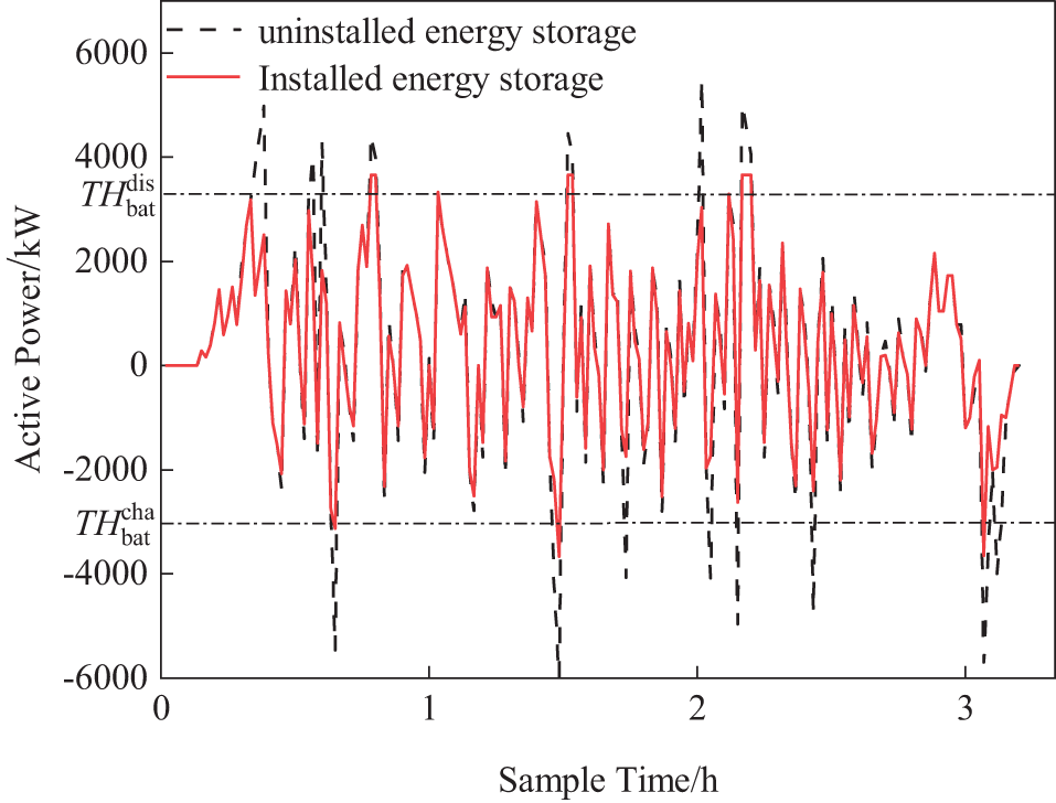
Figure 6: Active power on the secondary side of traction transformer
The optimized discharge and charge thresholds of the lithium batteries meet the requirements of the energy management strategy, achieving the goals of peak shaving and valley filling while reducing the regenerative braking power fed back to the traction network. This confirms the effectiveness of the energy storage system in enhancing power quality and efficiency.
Fig. 7 shows the output power and SOC of the supercapacitor. As can be seen from the figure, the supercapacitor performs high-frequency charging and discharging according to the energy management strategy, fully leveraging its advantages of high-power density and long cycle life. However, due to the energy density and SOC constraints, the stored energy of the supercapacitor is insufficient to support its maximum power output. It can be anticipated that a single supercapacitor cannot effectively achieve peak shaving and valley filling in an OESS. A hybrid OESS is better suited to meet the needs of the traction power supply system.
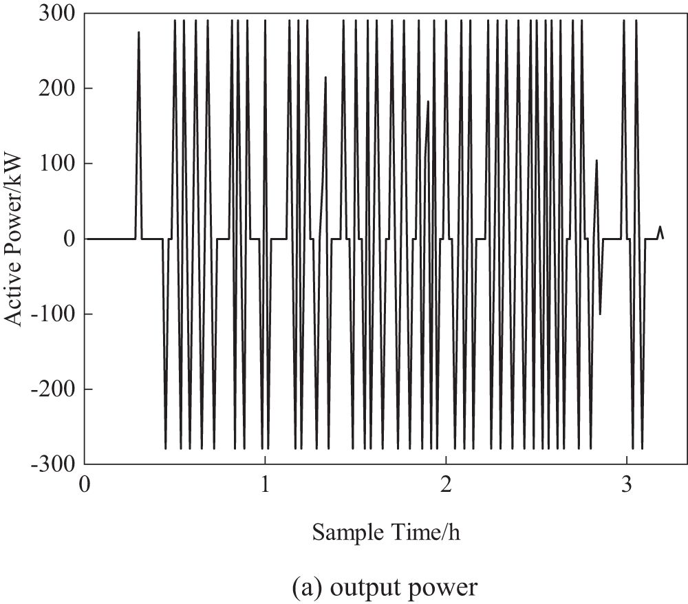
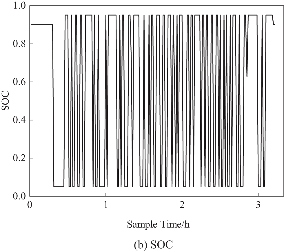
Figure 7: Output power and SOC of supercapacitors
Fig. 8 shows the output power and SOC of the lithium battery. As illustrated, the SOC of the lithium battery is maintained between 0.2 and 0.6. Thanks to the effective energy management strategy, the lithium battery does not undergo frequent charging and discharging and remains resting for extended periods. This greatly prolongs the battery’s lifespan, mitigating the disadvantage of the relatively short cycle life of lithium batteries.
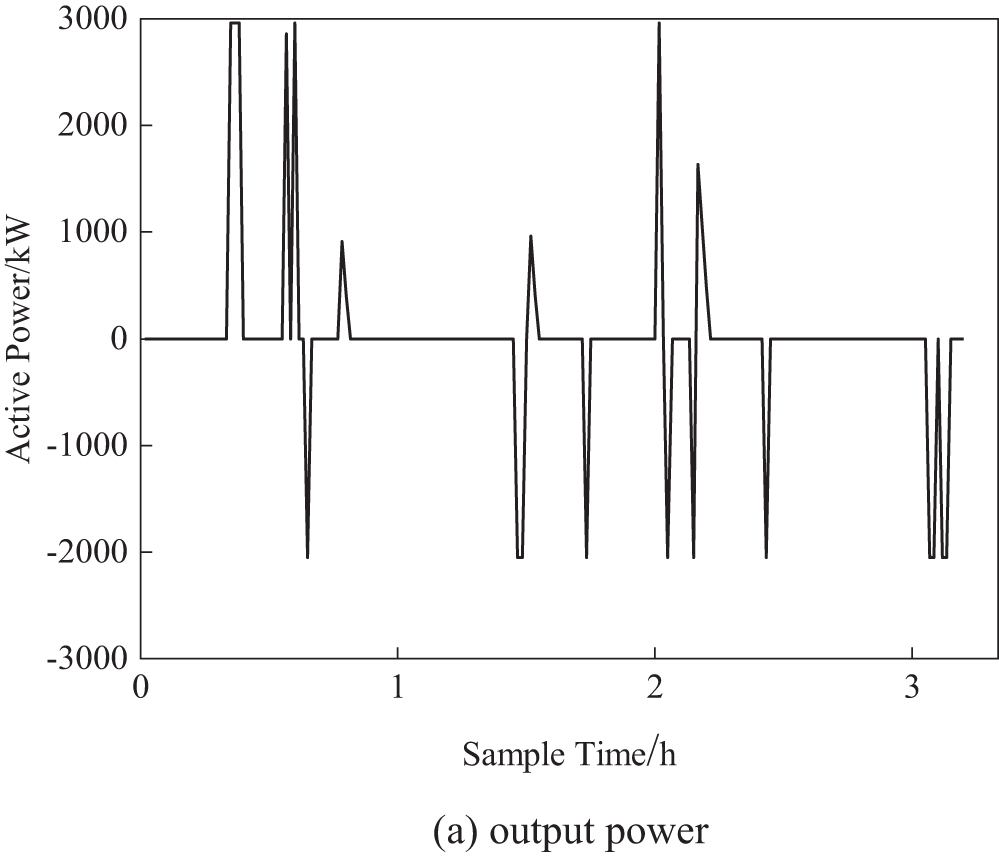
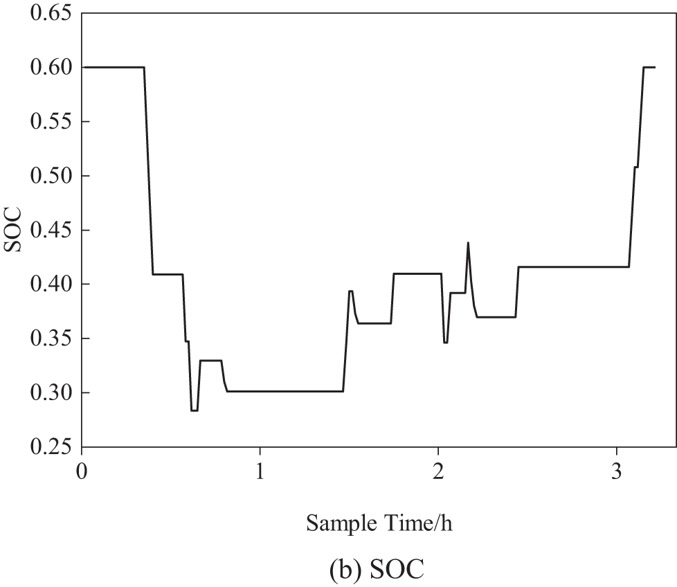
Figure 8: Output power and SOC of lithium batteries
6.3 Advantages and Challenges of the Model
The mathematical model presented in this paper effectively characterizes the macroscopic behavior of the OESS by integrating the electrical properties, weight, and volume of lithium batteries and supercapacitors into a cohesive framework. This macro-level approach facilitates the rapid evaluation of the system’s overall performance across different configurations without the need to delve into the intricate dynamics of individual components. However, it may not fully capture the micro-level dynamics such as battery aging and the degradation of supercapacitor performance. Furthermore, the model assumes a constant efficiency for both batteries and supercapacitors, potentially overlooking the actual impact of operational conditions like temperature variations on their performance.
The macro-model of the energy management strategy is capable of optimizing the charging and discharging behavior of the energy storage system holistically, achieving the objectives of peak shaving, valley filling, and enhancement of power quality. Controlling the charging and discharging thresholds of lithium batteries and supercapacitors enables the energy storage system to operate at its optimal performance under various operating conditions. However, this macro-model of the energy management strategy may not fully account for the impact of instantaneous grid fluctuations and unpredictable load changes on the performance of the energy storage system.
Incorporating the demand-side benefits and the full lifecycle costs of the energy storage system, the bi-level programming model is capable of providing the most cost-effective energy storage solutions for electrified railways. Although the bi-level programming model offers optimization strategies at a macro level, it may not fully consider operational constraints that may arise in practice, such as the real-time response capabilities of the energy storage system and the dynamic changes in the power grid. Furthermore, the optimization outcomes of the model may be sensitive to parameter variations, necessitating regular model calibration and updates for practical application.
Table 4 presents a comparison of the effects of two energy storage solutions. The alternative solution considers the constraints of train load and space but does not use the capacity configuration optimization method proposed in this paper. This alternative solution optimizes the number of energy storage modules as variables, with the system’s annual net profit as the optimization goal, and solves the problem using CPLEX.

The comparative analysis indicates that although the alternative solution achieves similar parameters in terms of maximum power reduction and regenerative braking energy utilization, it requires significantly more lithium batteries than the proposed solution. This results in the alternative solution’s energy storage system fully occupying the train’s available load capacity, adversely affecting the railway transport system’s carrying capacity. In contrast, the capacity configuration optimization method proposed in this paper meets the DC/DC converter’s requirements for the number of series/parallel connections of energy storage modules and the train’s load and space constraints. Additionally, it considers the load demand for passenger use, thus ensuring system performance and profitability while preserving part of the train’s carrying capacity.
To address the issues of peak traction load power and regenerative braking power recovery and utilization in electrified railways, a mathematical model and capacity optimization method for an OESS using lithium batteries and supercapacitors are proposed. Additionally, an energy management strategy is presented, which comprehensively considers peak shaving, valley filling, and power quality improvement. By analyzing the load data of a CRH5 high-speed train operating on a specific line, the following conclusions are drawn:
1) Model Efficacy: The proposed OESS mathematical model ensures that the series/parallel configurations of the energy storage modules meet the constraints of the DC/DC converter, while also ensuring the storage medium operates within a safe charging range.
2) Optimization of Capacity Configuration: The capacity optimization method takes into account the constraints of train load and space, effectively retaining a portion of the train’s carrying capacity. Under optimal capacity configuration, the OESS is expected to achieve a net profit of 7.296 million yuan over its entire life cycle, demonstrating significant economic benefits.
3) Energy Management Strategy: Under the proposed energy management strategy, the OESS can effectively perform peak shaving and valley filling. The application of this system significantly reduces the regenerative braking power fed back to the traction network, from 5990 kW without storage to 3658.5 kW, and improves the utilization rate of regenerative braking energy to 26.7%.
With continuous advancements in energy storage manufacturing technology, reduction in energy storage weight, and decreasing prices, there is significant potential for further development of OESS in electrified railways in the future.
Acknowledgement: None.
Funding Statement: This research was funded by the National Natural Science Foundation of China (52167013), the Key Program of Natural Science Foundation of Gansu Province (24JRRA225) and Natural Science Foundation of Gansu Province (23JRRA891).
Author Contributions: The authors confirm contribution to the paper as follows: study conception and design: Mingxing Tian, Weiyuan Zhang; data collection: Zhaoxu Su; analysis and interpretation of results: Weiyuan Zhang; draft manuscript preparation: Weiyuan Zhang. All authors reviewed the results and approved the final version of the manuscript.
Availability of Data and Materials: The authors confirm that the data supporting the findings of this study are available within the article.
Ethics Approval: Not applicable.
Conflicts of Interest: The authors declare that they have no conflicts of interest to report regarding the present study.
References
1. H. J. Kaleybar, M. Brenna, F. Foiadelli, S. S. Fazel, and D. Zaninelli, “Power quality phenomena in electric railway power supply systems: An exhaustive framework and classification,” Energies, vol. 13, no. 24, Dec. 2020, Art. no. 6662. doi: 10.3390/en13246662. [Google Scholar] [CrossRef]
2. T. R. D. Silva, B. Moura, and H. Monteiro, “Life cycle assessment of current Portuguese railway and future decarbonization scenarios,” Sustainability, vol. 15, no. 14, pp. 1–15, Jul. 2023. doi: 10.3390/su151411355. [Google Scholar] [CrossRef]
3. Z. Y. He, H. T. Hu, and L. Fang, “Research on the harmonic in high-speed railway traction power supply system and its transmission characteristic,” (in Chinese), Proc. CSEE, vol. 31, no. 16, pp. 55–62, Jun. 2011. doi: 10.13334/j.0258-8013.pcsee.2011.16.007. [Google Scholar] [CrossRef]
4. E. Fedele, D. Iannuzzi, and A. D. Pizzo, “Onboard energy storage in rail transport: Review of real applications and techno-economic assessments,” IET Electr. Syst. Transp., vol. 11, no. 4, pp. 279–309, Dec. 2021. doi: 10.1049/els2.12026. [Google Scholar] [CrossRef]
5. J. A. Aguado, A. J. S. Racero, and S. D. L. Torre, “Optimal operation of electric railways with renewable energy and electric storage systems,” IEEE Trans. Smart Grid, vol. 9, no. 2, pp. 993–1001, Mar. 2018. doi: 10.1109/TSG.2016.2574200. [Google Scholar] [CrossRef]
6. E. Pameté et al., “The many deaths of supercapacitors: Degradation, aging, and performance fading,” Adv. Energy. Mater., vol. 13, no. 29, Jun. 2023, Art. no. 2301008. doi: 10.1002/aenm.202301008. [Google Scholar] [CrossRef]
7. S. L. Wu et al., “Dilute aqueous-aprotic electrolyte towards robust Zn-ion hybrid supercapacitor with high operation voltage and long lifespan,” Nano-Micro Lett., vol. 16, no. 161, pp. 1–12, Mar. 2024. doi: 10.1007/s40820-024-01372-x. [Google Scholar] [PubMed] [CrossRef]
8. K. Xu, Y. G. Guo, G. Lei, and J. G. Zhu, “A review of flywheel energy storage system technologies,” Energies, vol. 16, no. 18, pp. 6462–6494, Sep. 2023. doi: 10.3390/en16186462. [Google Scholar] [CrossRef]
9. U. Hyuck et al., “High-energy-density Li-ion battery reaching full charge in 12 min,” ACS Energy Lett., vol. 7, no. 11, pp. 3880–3888, Sep. 2022. doi: 10.1021/acsenergylett.2c02032. [Google Scholar] [CrossRef]
10. F. Y. Gao, H. R. Zhang, and W. X. Wang, “Energy saving operation optimization of hybrid energy storage system for hydrogen fuel cell tram,” (in Chinese), Trans. China Electrotech. Soc., vol. 37, no. 3, pp. 686–696, Feb. 2022. doi: 10.19595/j.cnki.1000-6753.tces.201645. [Google Scholar] [CrossRef]
11. Y. Wang, Z. P. Yang, and F. Li, “Energy management strategy with energy interaction and configuration optimization for the trams hybrid storage system,” (in Chinese), Trans. China Electrotech. Soc., vol. 34, no. 8, pp. 1780–1788, Apr. 2019. doi: 10.19595/j.cnki.1000-6753.tces.201645. [Google Scholar] [CrossRef]
12. L. Pugi and L. di Carlo, “Multi-modal battery-operated trains on partially electrified lines: A case study on some regional lines in Italy,” Proc. Inst. Mech. Eng. F: J. Rail Rapid Transit., vol. 238, no. 7, pp. 873–885, Aug. 2024. doi: 10.1177/09544097241234959. [Google Scholar] [CrossRef]
13. Y. Dvorkin, R. F. Blanco, and D. S. Kirschen, “Ensuring profitability of energy storage,” IEEE Trans. Power Syst., vol. 32, no. 1, pp. 611–623, 2016. doi: 10.1109/TPWRS.2016.2563259. [Google Scholar] [CrossRef]
14. Z. M. Li, T. K. Wang, and P. F. Hu, “Bi-level collaborative configuration optimization of biogas-wind-solar integrated energy system based on energy hub,” (in Chinese), Electr. Power, vol. 57, no. 4, pp. 1–13, Apr. 2024. doi: 10.11930/j.issn.1004-9649.202303062. [Google Scholar] [CrossRef]
15. K. Qu and J. X. Yuan, “Optimizing research on hybrid energy storage system of high-speed railway,” IET Gener. Transm. Distrib., vol. 36, no. 19, pp. 2835–2846, May 2021. doi: 10.1049/gtd2.12217. [Google Scholar] [CrossRef]
16. J. X. Chen, Y. Wang, and X. Q. Chen, “A vehicle energy storage solution considering voltage fluctuation and harmonic control of traction network in mountainous area,” (in Chinese), J. Rly. Sci. Eng., vol. 18, no. 6, pp. 1528–1594, Jun. 2021. doi: 10.19713/j.cnki.43-1423/u.T20200793. [Google Scholar] [CrossRef]
17. Z. B. Tian, N. Zhao, S. Hillmansen, S. A. Su, and C. L. Wen, “Traction power substation load analysis with various train operating styles and substation fault modes,” Energies, vol. 13, no. 11, pp. 1–20, Jun. 2020. doi: 10.3390/en13112788. [Google Scholar] [CrossRef]
18. J. Chen et al., “An energy storage system for recycling regenerative braking energy in high-speed railway,” IEEE Trans. Power Deliv., vol. 36, no. 1, pp. 320–330, Feb. 2020. doi: 10.1109/TPWRD.2020.2980018. [Google Scholar] [CrossRef]
19. T. Li and Y. B. Shi, “Application of MMC-RPC in high-speed railway traction power supply system based on energy storage,” Appl. Sci., vol. 12, no. 19, pp. 1–19, Oct. 2022. doi: 10.3390/en14020484. [Google Scholar] [CrossRef]
20. M. Tanta et al., “Experimental validation of a reduced-Scale rail power conditioner based on modular multilevel converter for AC railway power grids,” Energies, vol. 14, no. 2, pp. 1–27, Jan. 2021. doi: 10.3390/en14020484. [Google Scholar] [CrossRef]
Cite This Article
 Copyright © 2025 The Author(s). Published by Tech Science Press.
This work is licensed under a Creative Commons Attribution 4.0 International License , which permits unrestricted use, distribution, and reproduction in any medium, provided the original work is properly cited.


 Submit a Paper
 Propose a Special lssue
 View Full Text
 Download PDF
 Downloads
 Citation Tools