
 Submit a Paper
 Propose a Special lssue
 Open Access
ARTICLE

Partitioning Calculation Method of Short-Circuit Current for High Proportion DG Access to Distribution Network
1 Anhui Electric Power Dispatch and Control Center, State Grid Anhui Electric Power Co., Ltd., Hefei, 230000, China
2 School of Electrical Engineering, Beijing Jiaotong University, Beijing, 100000, China
* Corresponding Author: Shaoliang Wang. Email:
Energy Engineering 2024, 121(9), 2569-2584. https://doi.org/10.32604/ee.2024.051409
Received 05 March 2024; Accepted 25 June 2024; Issue published 19 August 2024
 View Full Text
 Download PDF
Abstract
Aiming at the problem that the traditional short-circuit current calculation method is not applicable to Distributed Generation (DG) accessing the distribution network, the paper proposes a short-circuit current partitioning calculation method considering the degree of voltage drop at the grid-connected point of DG. Firstly, the output characteristics of DG in the process of low voltage ride through are analyzed, and the equivalent output model of DG in the fault state is obtained. Secondly, by studying the network voltage distribution law after fault in distribution networks under different DG penetration rates, the degree of voltage drop at the grid-connected point of DG is used as a partition index to partition the distribution network. Then, iterative computation is performed within each partition, and data are transferred between partitions through split nodes to realize the fast partition calculation of short-circuit current for high proportion DG access to distribution network, which solves the problems of long iteration time and large calculation error of traditional short-circuit current. Finally, a 62-node real distribution network model containing a high proportion of DG access is constructed on MATLAB/Simulink, and the simulation verifies the effectiveness of the short-circuit current partitioning calculation method proposed in the paper, and its calculation speed is improved by 48.35% compared with the global iteration method.Keywords
In the process of building a new type of power system with clean energy as the main body, the large-scale promotion of inverter-type distributed generation (Distributed Generation, DG), mainly wind power and photovoltaic, makes the distribution of grid currents and short-circuit currents change [1]; and the voltages and currents in different locations of the network are affected by DG to different extents, with lines close to the DG being affected to a large extent, and lines far away from the DG being affected to a small extent [2]. On the other hand, unlike traditional synchronous generators, the fault output characteristics of DG are affected by their converter control strategy, and their output current magnitude is limited by the converter limit current limit [3], which makes the traditional short-circuit current calculation no longer applicable. The short-circuit current calculation is the main basis for power system equipment selection and relay protection adjustment [4], therefore, in-depth research on short-circuit current calculation of distribution networks containing a high percentage of DG access is needed.
Before carrying out the short-circuit current calculation of the distribution network containing DG, the equivalent model of DG needs to be established first. Literature [5] considers the DG control strategy and equates the DG to a voltage-controlled current source model in distribution network fault analysis; Literature [6] derives the DG symmetric fault model under active/reactive power (PQ) control strategy, and on this basis carried out the symmetric fault analysis of distribution network with inverter interfaced distributed generators (IIDG). Then IIDG is described as a voltage-controlled current source or a voltage-controlled voltage source according to whether the modulation is limited; Literature [7] fits the new energy output characteristics segmentally and constructs the segmental function curves of the new energy power output current and its grid-connected voltage; although different DG equivalent models can be established, it is necessary to establish the equivalent model of the DG. DG equivalent models can be established, but in different application scenarios, the corresponding DG equivalent models need to be established.
After establishing the DG fault equivalent model, the short-circuit current is calculated for the distribution network. Literature [8] considers distributed power supply as an Alternating Current (AC) power supply with sudden current change at short circuit to calculate the periodic component of current, but does not consider the influence of low voltage crossing strategy on distributed power supply; In literature [9], the short-circuit current calculation process is modeled as an iterative linear system calculation based on the symmetric component method, but the calculation efficiency based on the symmetric component method is low; Literature [10] proposes an iterative calculation method of short circuit current using piecewise function equation as the modified equation. This method can accurately calculate the short circuit current value using the control strategy, but at the same time, the calculation time is too long; Literature [11] establishes the loop voltage function during the fault period of the distribution network including DG, and proposed an iterative correction method to solve the function, so as to calculate the short-circuit current. However, this method is greatly affected by fault location and network structure. In the above studies, the global iterative algorithm was used in the calculation process for short-circuit current calculation, although the methods were different. Although the accuracy is high, with the expansion of the grid size and the increase of DG penetration, it will lead to the global iteration algorithm being too time-consuming and less efficient.
Therefore, some scholars have begun to consider the use of localized iterative methods that iterate over a portion of the region. Literature [12] uses a constant current source as the fault downstream DG output model and iteratively calculates the DG only for the fault upstream region. However, the short-circuit current still needs to be calculated globally in the end. Literature [13] divides the nodes into faulty and non-faulty point sets based on topological constraints according to the degree of node voltage drop after a grid fault and performs iterative calculations separately. However, this partitioning makes the reduction of iteration area limited due to the fact that the node voltages are basically less than 0.9UN after the grid fault, and dividing all these nodes into faulty areas will make the iteration area too large, resulting in a long iteration time; Literature [14] bases on the location of the DG distribution, and the area with high density and similar location of the DG distribution is treated as a sub-area. However, this partitioning method is not applicable to the case of faults occurring in the zone.
To address the above problems, a partitioning calculation method of short-circuit current for high proportion DG access to distribution network is proposed in the paper. Firstly, the output characteristics of DG during low voltage ride through (LVRT) are analyzed, the output current of DG during fault is theoretically derived, and the equivalent model of DG under fault steady state is established. Secondly, combined with the DG fault output characteristics, the distribution network was partitioned according to the degree of voltage drop at the grid-connected point after the fault point and the fault location. Then, iterative computation is performed within each partition, and data are transferred between partitions through split nodes to realize the fast partition calculation of short-circuit current for high proportion DG access to distribution network. Finally, on the MATLAB/Simulink platform, a 62-node real distribution network model containing a high proportion of DG access is constructed and simulated for verification. The results show that the proposed short-circuit current calculation method is not affected by fault location and DG penetration rates, and the calculation results satisfy the engineering requirements, and it has a faster calculation speed, which is 48.35% higher compared with the global iterative method.
2 Equivalent Output Model of DG after Distribution Network Fault
According to the technical regulations of inverter-type DG accessing the power system, it is required that the DG accessing the distribution grid needs to meet the requirements of LVRT capability when a fault occurs in the grid [15], as shown in Fig. 1, for the LVRT capability requirements of inverter-type DG. When different types of fault occur in the grid, the inverter-type DG must ensure that it does not go off-grid for continuous operation and outputs a certain amount of reactive power to play the role of voltage support; otherwise, the inverter-type DG is allowed to be cut out from the grid.
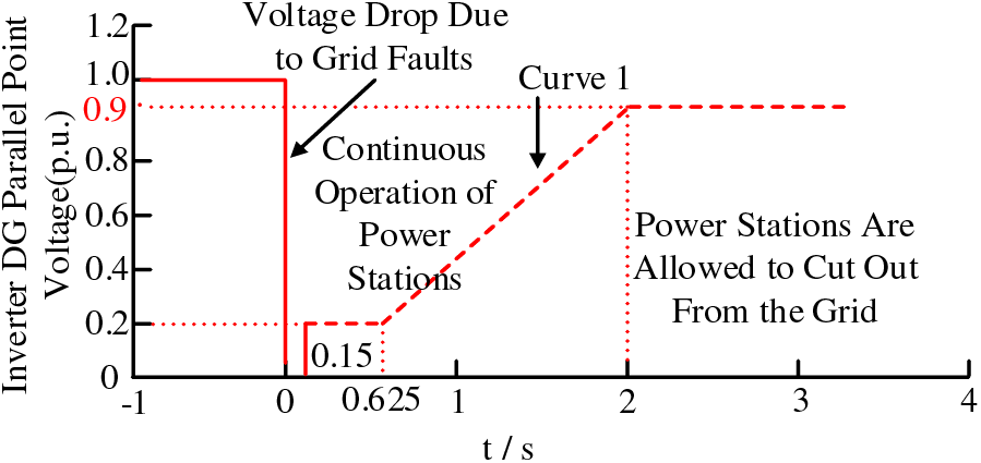
Figure 1: Low voltage ride-through diagram of inverter power supply connected to grid
Various types of inverter-type power supplies have different characteristics, and according to the above grid-connected criteria, in the event of a fault in the grid that causes a drop in the system voltage, the inverter-type DG must inject a dynamic reactive current Iq into the grid according to the degree of the drop in the voltage at the grid-connected point, as shown in Eq. (1):
where, Id and Iq are dq-axis components of the DG output current; Upcc is the voltage at the grid-connected point of DG; UN is the rated voltage at the grid-connected point of DG; and IN is the rated output current of the DG.
Meanwhile, according to the national standard GB 50797-2012, the output current of the inverter-type DG is not more than 1.2IN. Therefore, it is necessary to limit the current of the DG to avoid the damage of the power electronic devices, as shown in Eq. (2):
where, IDG is the amplitude of the DG output current and Kmax is the maximum allowable coefficient of the output current.
In addition, under the premise that Eqs. (1) and (2) need to be satisfied, in order for the DG to emit maximum active power without overcurrent, the DG output active current Id should be as shown in Eq. (3):
where, Pref is the DG output active power reference value, 2Pref/3Upcc indicates the DG output active current value under normal conditions.
When a fault occurs, the DG control enters the LVRT mode, at which time the output current reference values are determined by the LVRT capability requirements. Therefore, combining Eqs. (1)–(3) gives the DG running during LVRT output active current id* and reactive current iq* reference values as Eq. (4):
Since the DG keeps the normal control strategy unchanged when Upcc > 0.9UN, it is only necessary to establish the equivalent model of DG after fault according to the latter two cases in Eq. (4), as shown in Fig. 2. When 0.9UN > Upcc > 0.2UN, the DG enters the LVRT mode to provide partial reactive power support to the grid according to the degree of voltage drop, which can be equated to a voltage-controlled current source; and when Upcc < 0.2UN, the DG output current is limited, which can be equated to a constant current source.
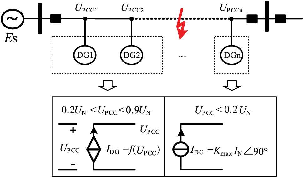
Figure 2: Equivalent form diagram of grid-connected DG access
3 Power Grid Partition Based on Fault Voltage Distribution
3.1 Analysis of Voltage Variation Characteristic at the Grid-Connected Point of DG during Fault
Since the output current of the DG during fault is mainly affected by the voltage at the grid-connected point, in order to simplify the iterative calculations for high proportion DG, it is necessary to analyze the variation characteristics of the voltage at the grid-connected point of DG during fault. The topology of the distribution network shown in Fig. 3 is used as an example to analyze the variation characteristics of the voltage at the grid-connected point of DG during fault. In Fig. 3, four DGs are connected on the line, the line impedance parameters are ZS + Z1 = Z2 = Z3, Z4 = Z5 = Z6, and Z4 = 1.857Z3, and a three-phase metallic short-circuit fault occurs at the point of f on the line.
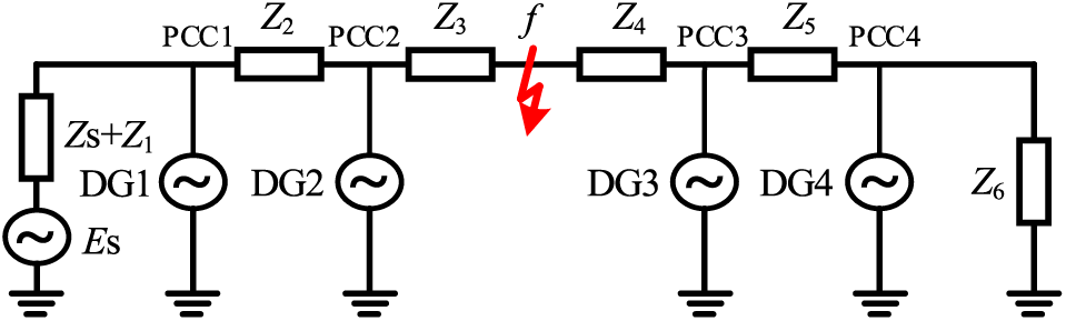
Figure 3: Relationship between DG and fault location in typical distribution network
Let the system power supply Es = 1 p.u., DG output is rated current, according to the superposition theorem, the voltage at the grid-connected point of DG during fault is:
(1) DG located upstream of the fault
(2) DG located downstream of the fault
where, Zs is the system impedance, Zi (1 ≤ i ≤ 6) is the line impedance, and IDGi and UPCCi (1 ≤ i ≤ 4) are the current and the voltage at the grid-connected point of the ith DG output at the time of fault.
Substituting each data parameter into Eqs. (5) and (6), the voltage at the grid-connected point of the four DGs can be obtained as shown in Table 1:
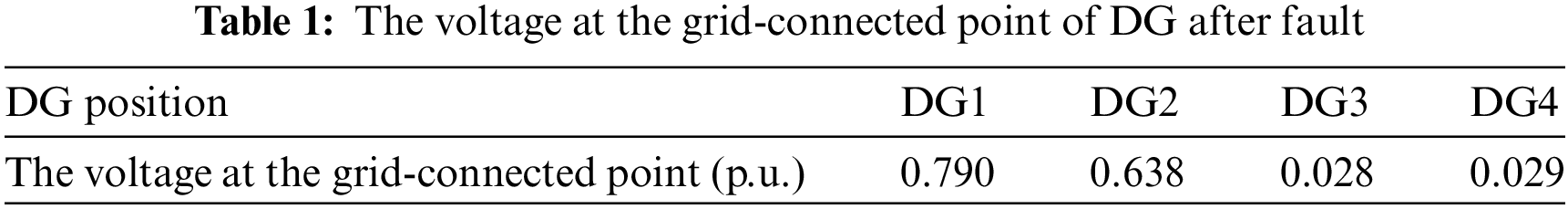
According to the data in the table, it can be seen that the degree of voltage drop at the grid-connected point of DG1 and DG2 located upstream of the fault is small, which is higher than 0.2UN; the degree of voltage drop at the grid-connected point of DG3 and DG4 located downstream of the fault is large, which is lower than 0.2UN. This is due to the fact that the voltage at the grid-connected point of DG located upstream of the fault is supported by the system power supply and the DG, and the voltage at the grid-connected point of DG located downstream of the fault is only supported by the DG, which is the reason for the similar degree of drop of DG parallel points. Therefore, the voltage at the grid-connected point of DG located upstream of the fault is small, and the voltage at the grid-connected point of DG located downstream of the fault is large.
3.2 Effect of DG Penetration Rates on the Voltage at the Grid-Connected Point
The previous section did not consider the effect of DG penetration rates, in order to analyze the effect of DG penetration rates on the voltage at the grid-connected point, the following still takes Fig. 3 as an example to analyze the change of the degree of voltage drop at the grid-connected point when a three-phase metallic short-circuit fault occurs at point f and the DG penetration rates gradually rises from 20% to 90%.
When the DG penetration rates changes, its rated current IDGi will also change accordingly. Substituting different IDGi parameters into Eqs. (5)–(8), the voltage of each grid-connected point can be obtained at different DG penetration rates and the degree of voltage drop at each grid-connected points can be found according to Eq. (9):
where, α is the voltage drop coefficient and UN is taken as 1 p.u. The degree of voltage drop at each grid-connected points is obtained as shown in Table 2:
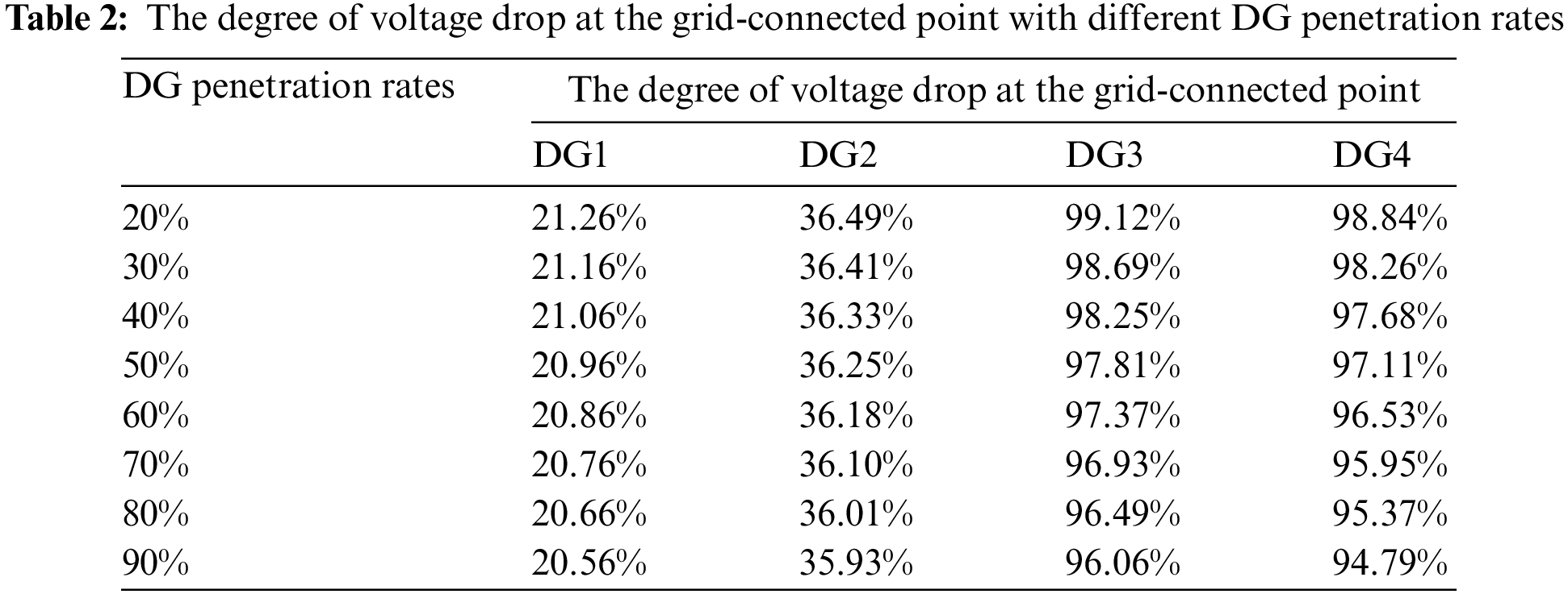
Here, in order to analyze the impact of DG penetration rate on the voltage at the grid-connected point, the DG penetration rate is increased to 90%, but in the actual distribution network, the DG penetration rate will be taken into account in the voltage level, short-circuit current level and other factors of system stable operation to give the maximum access capacity constraints of the DG, and if it is more than the maximum access capacity constraints, in order to ensure the reliable operation of the system, it will generally take the measures of installing reactive power compensation devices and other measures.
As can be seen from the data in the table, with the increase in DG penetration rates, the line voltage has increased to a lesser extent though. However, overall, the degree of voltage drop at the grid-connected point has not been greatly changed. This indicates that the degree of voltage drop at the grid-connected point is mainly related to the fault location, and the influence of DG penetration rates on the voltage at the grid-connected point is very small. In order to verify this conclusion, the distribution network model shown in Fig. 3 was simulated on the MATLAB/Simulink platform, and the simulation results are shown in Fig. 4.
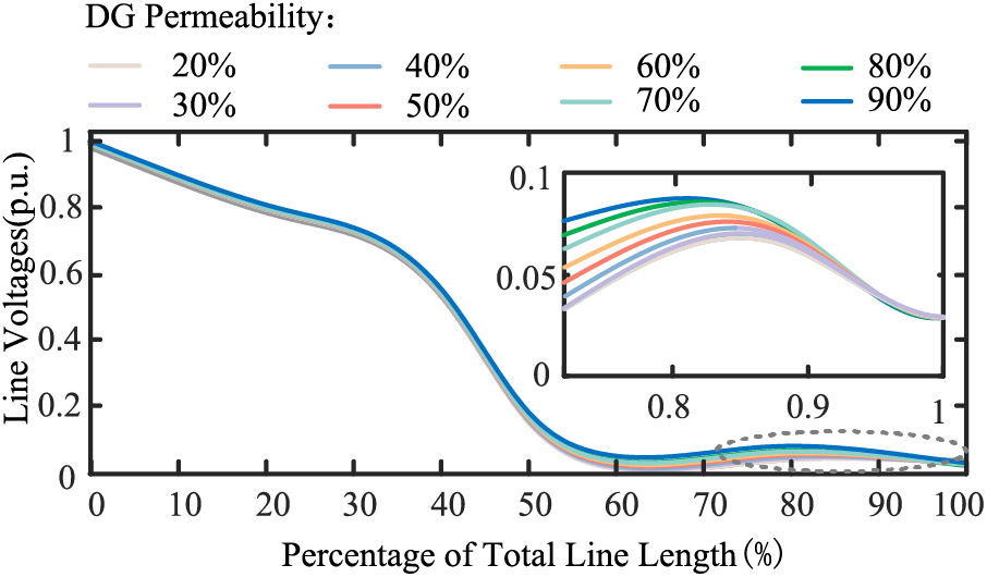
Figure 4: Simulation results of line voltage with different DG penetration rates
From the figure, it can be seen that the line voltage increases with the DG penetration rates, but the change is not significant. When the DG penetration rates is elevated from 20% to 90%, the degree of change of line voltage is within the (0%, 4%) interval, which shows that the degree of voltage enhancement by DG penetration rates is limited. It is verified that when a short-circuit fault occurs in the distribution network, the degree of voltage drop at the at the grid-connected point of DG is mainly related to the fault location, with a small degree of voltage drop at the grid-connected point upstream of the fault, and a large degree of voltage drop at the grid-connected point downstream of the fault with similar voltage magnitude.
3.3 Distribution Network Partition Method
According to the change law of the voltage at the grid-connected point of DG during fault, the distribution grid is partitioned based on the fault location, as shown in Fig. 5. In the figure, the grid is partitioned into the upstream region of the fault and the downstream region of the fault, and zf is the grounding impedance. In the partitioning equivalence process, the fault point f is split into split node f1 and split node f2. When calculating, intra-area iteration is carried out for the two partitions respectively, and the data are transferred between the areas through the split nodes.

Figure 5: Distribution network partition method
As located in the upstream DG of the fault point, the degree of voltage drop at the grid-connected point is small, which are all greater than 0.2UN, the DG outputs short-circuit current according to the low-voltage ride-through strategy; while located in the downstream DG of the fault point, the voltage drop degree is high, which are all lower than 0.2UN, the DG enters into the current-limiting state, and provides the maximum output current outward in the form of a constant current source. Therefore, this partition method can realize the iteration of DGs with similar output states at the same time, which reduces the number of iterations and improves the computational efficiency, and is conducive to the popularization and application in engineering.
4 Calculation of Short-Circuit Current Based on Partition Iterative Algorithm
According to the superposition theorem, both the fault upstream region and the fault downstream region shown in Fig. 5 are decomposed into the normal component network and the fault component network, and then the short-circuit current partition calculation begins, and the specific process is shown in Fig. 6.

Figure 6: Partitioning calculation process of short-circuit current
4.1 Iteration within the Downstream of the Fault
Given the initial iteration parameters of the network in the partition, the initial output power of the DG is firstly derived based on the DG equivalent model and the instantaneous power theory, as in Eq. (10):
where, PDGi and QDGi are the active and reactive power output from the DG at node i; udi and uqi are the d-axis and q-axis voltage components of the DG merging voltage at node i; and idi and iqi are the active and reactive current output from the DG at node i.
With DG as PQ node and split node f2 as balance node, the power flow of normal component network is calculated, and the normal voltage components
The initial short-circuit current is then solved using the fault component network as in Eq. (11):
where,
Based on the obtained initial short-circuit current
where,
And based on the superposition theorem, the normal component of voltage at each node is superimposed with the fault component to obtain the voltage at each node after short circuit as in Eq. (13):
where,
At this time, the DG merging point voltage at the tth iteration is known, and the DG state is updated according to the merging point voltage. Repeat the above steps until the error requirement is satisfied, as in Eq. (14):
where,
At this point, the iteration in the downstream of the fault is completed, and the output current of the DG after the fault is obtained along with the voltage at each node.
After the downstream iteration is completed, the output current of the DG in the partition is known, and its output power is derived according to Eq. (10) and transformed into a constant impedance model ZDG, as in Eq. (15):
where, n is the number of DGs in the downstream region, ZDGj is the constant impedance model of the jth DG in the downstream region, PDGj and QDGj are the active and reactive power output from the jth DG in the downstream region, and Upccj is the grid point voltage of the jth DG in the downstream region.
Then, the power flow of downstream normal component network is calculated without considering DG, and the transmission power
where,
It is added to the DG constant impedance model ZDG and appended at the split node f1 in the region upstream of the fault, as shown in Fig. 7. Then, the partition iteration is started for the upstream of the fault.

Figure 7: Upstream of the fault
4.3 Iteration within the Upstream of the Fault
The iterative process in the upstream region is similar to that in the downstream region, with the difference that since the effect of the faulted downstream region on the upstream region has already been taken into account as a constant impedance model, the short-circuit current obtained by iteration within the faulted upstream region is the final result, that is, the short-circuit current
5 Simulation Verification and Analysis of Influencing Factors
Based on the MATLAB/Simulink simulation platform, the simulation model of the distribution network system containing a high proportion of DG access is established as shown in Fig. 8, taking the actual distribution network in a province and city as an example. The model contains 62 nodes, the number of DG accesses is 30, the penetration rates is 25.5%, the voltage level is 10 kV, the base power is 10 MVA, and the initial amplitude and phase angle of the voltage at each node are set to 1 p.u. and 0°. The rest of the line parameters and DG capacity etc., use the actual parameters of this distribution network. A three-phase short-circuit fault is set up at node 19, and the fault point is grounded via a resistor R of magnitude 0.01 Ω.
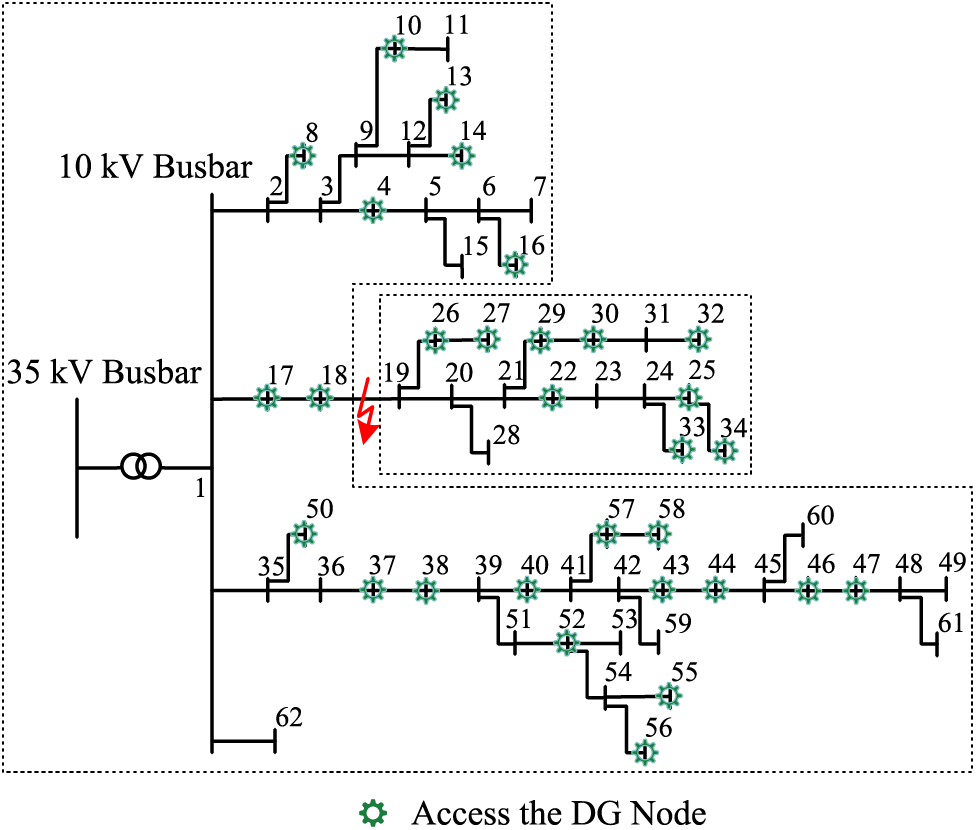
Figure 8: Topology of the actual distribution network of a province or city
5.1 Validation of DG Steady State Equivalent Models
In order to verify the correctness of the DG equivalent model constructed by Eq. (4), it is compared with the actual model of DG. Among them, the DG real model uses the PQ control strategy during normal operation, the negative sequence current cancellation strategy during asymmetrical faults as well as the LVRT control strategy during faults. When the voltage Upcc at the grid point drops to 0.5UN, the comparison results of the active current Id and the reactive current Iq output from the DG equivalent model and the actual model are shown in Fig. 9.

Figure 9: Active and reactive current output waveforms of DG equivalent model and actual model. (a) Active current output waveforms of DG equivalent model and actual model; (b) Reactive current output waveforms of DG equivalent model and actual model
It can be seen that at the instant of fault occurrence, due to the existence of DG transient state, there is a certain error between the equivalent model and the actual model outputs Id and Iq, with an error range of about 5.25%; after the DG reaches the steady state, the error between the equivalent model and the actual model outputs Id and Iq is very small, with a maximal error of 1.25%, which is able to satisfy the requirements of the protection and the calculation of short-circuit current. It shows that the DG equivalent model established in the paper can better represent the output characteristics of DG, verifies the correctness of the equivalent model established in the paper, and provides a theoretical basis for the calculation of short-circuit current zoning.
5.2 Effectiveness Analysis of Short-Circuit Current Partition Iterative Algorithm
Take the topology shown in Fig. 8 as an example. When a three-phase short-circuit fault occurs at node 19, the distribution network is divided into fault upstream area and fault downstream area according to the above-mentioned power grid partition method. Then, according to the calculation flow shown in Fig. 6, the partition iterative calculation is started.
Firstly, the downstream region of the fault point is iterated within the region, and after obtaining the network parameters, node 19′ is taken as the balancing node, and the initial voltage normal component of each node in the downstream region is obtained by giving the initial value of each DG within the region, solving the initial output power of each DG according to Eq. (10), and carrying out the initial current computation; then, the initial short-circuit component of the fault point is obtained according to Eq. (11) current, and solve each node voltage fault component according to Eq. (12), superimpose it with the node voltage normal component according to Eq. (13) to obtain the first iterative value of the node voltage of the downstream region of the fault; and then update the DG state according to the DG equivalent model of Eq. (4). Repeat the above steps until the convergence requirement of Eq. (14) is satisfied.
At this point, the state of DG in the region downstream of the fault no longer changes, which is transformed into a constant impedance model according to Eq. (15), and the power supplied to the region downstream of the fault by the equilibrium node 19′ in the steady-state case is obtained by the tidal current calculation, which is also transformed into a constant impedance model according to Eq. (16), which is superimposed on the constant impedance model of the DG, and is attached to the node 19 of the region upstream of the fault, and it begins to performing the iteration within the region upstream of the fault point. Taking node 1 as the balancing node, given the initial value of each DG inside the region, iteration is started until the requirement of convergence accuracy is satisfied, and finally the voltage of each node and the short-circuit current at the fault point are obtained. The simulation model was built on the MATLAB/Simulink platform and compared with the calculation results, as shown in Fig. 10.
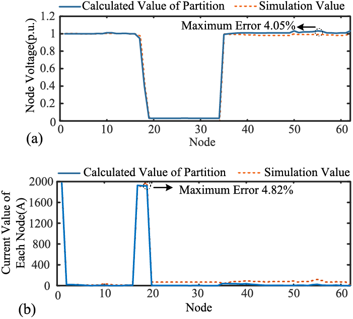
Figure 10: Comparison of partition calculated values and simulation results. (a) Comparison of partition calculated values of node voltage with simulation results; (b) Comparison of partition calculated values of node current with simulation results
It can be seen that, compared with the simulation results, the maximum error of the partition calculated value of the voltage at each node is 4.05%, and the maximum error of the partition calculated value of the current flowing through each node is 4.82%, which meets the engineering requirements. The validity of the short-circuit current partitioning calculation method proposed in the paper is verified.
5.3 Algorithm Performance Validation with Different Influencing Factors
5.3.1 Effect of Fault Location
In practical engineering, it is necessary to traverse all the fault cases between nodes to verify the correctness of the protection rectification value. In order to verify that the partition iterative algorithm can be applied to the short-circuit current calculation under different fault location cases, the short-circuit current calculation is carried out with nodes 3, 24, 38 and 46 as the fault nodes respectively in Fig. 8 and compared with the simulation values, and the results are shown in Fig. 11.

Figure 11: Comparison of partition calculated values of short-circuit current with simulation results. (a) Node 3 Fault; (b) Node 24 Fault; (c) Node 38 Fault; (d) Node 46 Fault
From Fig. 11a–d, it can be seen that the maximum error of the short-circuit current values calculated using the partition iterative algorithm is only 3.35% compared with the simulation results under different fault locations, which meets the engineering requirements. It shows that the short-circuit current calculation method proposed in the paper is not affected by the fault location.
5.3.2 Effect of DG Penetration Rates
Different DG penetration rates of distribution network access have different effects on the magnitude of short-circuit current. Therefore, in order to verify that the partition iterative algorithm can be applied to the calculation of short-circuit current in the case of different DG penetration rates, taking the short-circuit fault occurred at node 3 in Fig. 8 as an example, change the DG penetration rates from 10% to 50%, and compare the partition calculated value of the short-circuit current with the simulation results, and the error results are shown in Fig. 12.
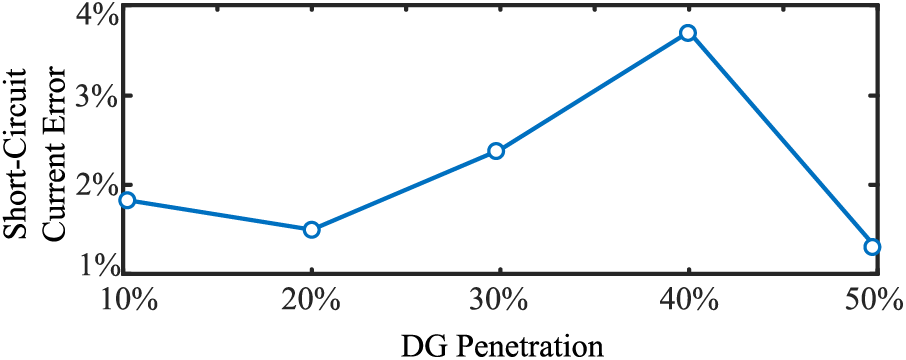
Figure 12: Short-circuit current error values for different DG penetration rates
As can be seen from the figure, the maximum error of the short-circuit current zonal calculation value in the case of different DG penetration rates does not exceed 4%, which can meet the engineering requirements. It is verified that the partition iterative algorithm proposed in the paper can be applied to the short-circuit current calculation under different DG penetration rates.
Since the partition iterative algorithm needs to partition the distribution network according to the fault location before it can be calculated compared with the global iterative algorithm, the partition iterative algorithm is compared with the global iterative algorithm in order to verify the superiority of the calculation speed of the partition iterative algorithm. The partition iterative algorithm and the global iterative algorithm are calculated 20 times, respectively, and the results of the calculation time are shown in Table 3. Among them, the calculation time of the partition iterative algorithm includes the process of establishing the distribution network partition model.
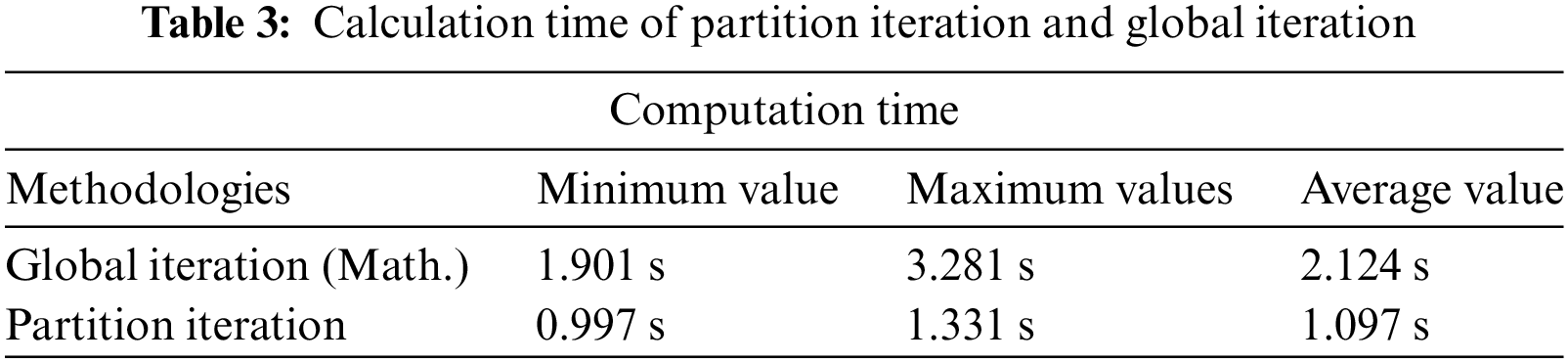
From the data in the table, it can be seen that in 20 calculations, the maximum, minimum and average values of the calculation time of the partition iteration are smaller than that of the global iteration, and the average time of the calculation is faster than that of the global iteration by 1.027 s, that is, 48.35%, which indicates that the partition iterative method can greatly reduce the calculation time. It means that when a fault occurs, the calculation time of each protection finalization will be reduced by 1.027 s, and the security will be greatly improved for the whole power distribution system. Therefore, the short-circuit current calculation using the partition iterative algorithm is conducive to the rapid adjustment of adaptive current protection, which can effectively improve the safety and stability of the system.
In the paper, a short-circuit current partitioning calculation method applicable to high proportion DG access to distribution networks is proposed, and the following conclusions are obtained by simulating and verifying the method on the MATLAB/Simulink platform:
1. The DG equivalent model constructed in the paper outputs Id and Iq values with a maximum error of only 1.25% compared with the actual model when a fault occurs in the distribution network, which is able to satisfy the requirements of protection and short-circuit current calculation.
2. In the paper, the distribution network partition according to the distribution law of node voltage after the fault can realize the iteration of DGs with similar output states at the same time, which greatly shortens the computation time, and improves the computation speed by 48.35% compared with the global iterative method, which is conducive to the rapid adjustment of adaptive current protection.
3. The short-circuit current partitioning calculation method proposed in the paper, which is applicable to high proportion DG access to distribution networks, is not affected by fault location and DG penetration rates, and the maximum error of short-circuit current calculation is 4.82% compared with the simulation results, which meets the engineering requirements and is expected to be popularized on a large scale in engineering.
Acknowledgement: Thanks to State Grid Anhui Electric Power Company for funding this paper.
Funding Statement: This project is funded by the National Natural Science Foundation of China (52077004) and Anhui Electric Power Company of the State Grid (52120021N00L). The project name is “Research on Fault Characteristics and Collaborative Technology of Control and Protection of New Power System Distribution Network”.
Author Contributions: The authors confirm contribution to the paper as follows: study conception and design: Wei Wang, Qingzhu Shao; data collection: Shaoliang Wang, Yiwei Zhao, Mengyu Wu; analysis and interpretation of results: Yuanbo Ye, Duanchao Li, Mengyu Wu; draft manuscript preparation: Shaoliang Wang, Yiwei Zhao. All authors reviewed the results and approved the final version of the manuscript.
Availability of Data and Materials: The data that support the findings of this study are available from the corresponding author, Shaoliang Wang, upon reasonable request.
Conflicts of Interest: The authors declare that they have no conflicts of interest to report regarding the present study.
References
1. K. Thomas et al., “Short-circuit model for type-IV wind turbine generators with decoupled sequence control,” IEEE Trans. Power Deliv., vol. 34, no. 5, pp. 1998–2007, Oct. 2019. [Google Scholar]
2. X. A. Hong, L. J. Tian, X. P. Yin, M. H. Xu, L. Han and X. Liu, “Influence of large-scale distributed photovoltaic access on harmonic characteristics of distribution network,” J. Phys. Conf. Ser., vol. 2592, no. 1, pp. 012076, Sep. 2023. doi: 10.1088/1742-6596/2592/1/012076. [Google Scholar] [CrossRef]
3. M. Behnam and F. J. Edward, “The equivalent models of grid-forming inverters in the sequence domain for the steady-state analysis of power systems,” IEEE Trans. Power Syst., vol. 35, no. 4, pp. 2876–2887, Jan. 2020. doi: 10.1109/TPWRS.2020.2968114. [Google Scholar] [CrossRef]
4. C. S. Ilik and B. A. Arsoy, “Effects of distributed generation on overcurrent relay coordination and an adaptive protection scheme,” IOP Conf. Ser. Earth Environ. Sci., vol. 73, no. 1, pp. 012026, Jul. 2017. [Google Scholar]
5. Z. L. Chen, Y. C. Tang, and W. Q. Lin, “Analysis of single-phase grounding fault with distributed generation in distribution network,” J. Phys. Conf. Ser., vol. 1887, no. 1, pp. 012021, Jun. 2021. [Google Scholar]
6. X. H. Shi et al., “Fault modeling of IIDG considering inverter’s detailed characteristics,” IEEE Access, vol. 8, pp. 183401–183410, Sep. 2020. doi: 10.1109/ACCESS.2020.3027323. [Google Scholar] [CrossRef]
7. J. B. Xu, X. Q. Ji, and M. F. Gong, “Reconfiguration method of active distribution network considering the output characteristics of distributed generation,” Electric Meas. Instrum., vol. 55, no. 13, pp. 53–59+73, Jul. 2018. [Google Scholar]
8. W. Cao, C. D. Ngon, J. C. Lin, and J. Sun, “Short-circuit current calculation of a power system with a grid-connected inverter,” Adv. Mater. Res., vol. 1070–1072, no. 1070–1072, pp. 823–828, Dec. 2014. doi: 10.4028/www.scientific.net/AMR.1070-1072.823. [Google Scholar] [CrossRef]
9. J. He, Z. Li, W. Li, J. Zou, X. Li and F. Wu, “Fast short-circuit current calculation of unbalanced distribution networks with inverter-interfaced distributed generators,” Int. J. Electr. Power Energy Syst., vol. 146, no. 2, p. 108728, Mar. 2023. doi: 10.1016/j.ijepes.2022.108728. [Google Scholar] [CrossRef]
10. X. P. Yang and C. Z. Jing, “Short-circuit current calculation method for distributed power distribution network with control strategies,” J. Phy. Conf. Ser., vol. 1314, no. 1, pp. 012045, Oct. 2019. [Google Scholar]
11. S. Wang, X. Jiang, Q. Li, and B. B. Huang, “Loop analysis method for short circuit current calculation of distribution network with inverter-interfaced distributed generators,” Energy Proc., vol. 158, no. 2, pp. 2909–2914, Feb. 2019. doi: 10.1016/j.egypro.2019.01.949. [Google Scholar] [CrossRef]
12. S. Yang and X. Q. Tong, “Calculation method of short-circuit current in distribution network with low-voltage ride-through distributed power supply,” Power Syst. Autom., vol. 40, no. 11, pp. 93–99+151, Jun. 2016. [Google Scholar]
13. K. Jia et al., “Engineering practical short-circuit current calculation of new energy based on local iteration of fault region,” Power Syst. Autom., vol. 45, no. 13, pp. 151–158, May 2021. [Google Scholar]
14. C. G. Wu, S. W. Xiao, and J. Zhu, “Calculation method of short-circuit current in distributed power grid with negative sequence voltage support,” Power Grid Technol., vol. 47, no. 3, pp. 1159–1169, Mar. 2023. [Google Scholar]
15. A. Ehsan et al., “Control strategy for three-phase grid-connected PV inverters enabling current limitation under unbalanced faults,” IEEE Trans. Ind. Electron., vol. 64, no. 11, pp. 8908–8918, Nov. 2017. [Google Scholar]
Cite This Article
 Copyright © 2024 The Author(s). Published by Tech Science Press.
This work is licensed under a Creative Commons Attribution 4.0 International License , which permits unrestricted use, distribution, and reproduction in any medium, provided the original work is properly cited.
 Downloads
 Citation Tools