
 Submit a Paper
 Propose a Special lssue
 Open Access
ARTICLE

Simulation Study of Diesel Spray Tilt Angle and Ammonia Energy Ratio Effect on Ammonia-Diesel Dual-Fuel Engine Performance
Mechanical and Automotive Engineering School, Shanghai University of Engineering Science, Shanghai, 201620, China
* Corresponding Author: Xuelong Miao. Email:
Energy Engineering 2024, 121(9), 2603-2620. https://doi.org/10.32604/ee.2024.051237
Received 01 March 2024; Accepted 22 April 2024; Issue published 19 August 2024
 View Full Text
 Download PDF
Abstract
Ammonia-diesel dual fuel (ADDF) engines for transportation applications are an important way to reduce carbon emissions. In order to achieve better combustion of ammonia in diesel engines. A small-bore single-cylinder engine was converted into an ADDF engine with the help of mature computational fluid dynamics (CFD) simulation software to investigate the performance of an engine with a high ammonia energy ratio (AER), and to study the effect of spray tilt angle on ADDF engine. The results showed that the increase in AER reduced nitric oxide (NO) and nitrogen dioxide (NO) emissions but increased nitrous oxide (NO) and unburned ammonia emissions. AER in the range of 50%–70% achieved lower greenhouse gases (GHG) emissions than the pure diesel mode. Relative to the pure diesel mode, when the AER was 60%, the indicated thermal efficiency (ITE) was increased by 0.2% and the GHG emissions were decreased by 22.3%, but carbon monoxide (CO) and Hydrocarbon (HC) emissions were increased. Increasing the in-cylinder combustion temperature or high-temperature region range of the ADDF engine could reduce GHG emissions. At an AER of 60%, an increase in the spray tilt angle helped the ammonia combustion in the residual gap to reduce the unburned ammonia emissions. Compared to the pure diesel mode with a spray tilt angle of 75°, an AER of 60% with a spray tilt angle of 77.5° improved the ITE by 1.5%, and reduced the GHG emissions by 25.7%. Adjusting the spray tilt angle of the ADDF engine also reduced CO and HC emissions. This is an effective way to improve ADDF engine performance by adjusting the spray tilt angle.Keywords
Nomenclature
| ADDF | Ammonia-diesel dual fuel |
| CFD | Computational fluid dynamic |
| ITE | Indicated thermal efficiency |
| CI | Compression ignition |
| AER | Ammonia energy ratio |
| LHV | Low heating value |
| GHG | Greengouse gases |
| SODI | Start of Diesel Injection |
| IMEP | Indicated Mean Effective Pressure |
| HRR | Heat release rate |
| CA10 | Crank angle (CA) at 10% of total in-cylinder fuel heat release |
| CA50 | Crank angle (CA) at 50% of total in-cylinder fuel heat release |
| CA90 | Crank angle (CA) at 90% of total in-cylinder fuel heat release |
| LPDF | Low-pressure injection dual fuel |
| HPDF | High-pressure injection dual fuel |
In order to cope with the greenhouse effect, internal combustion engine vehicles are transitioning to new energy vehicles thereby reducing emissions, while traditional fossil fuel combustion inevitably emits carbon dioxide, in pursuit of carbon neutrality, the development and use of sustainable alternative energy sources such as low/zero-carbon fuels applied to internal combustion engines is an important way to reduce carbon emissions [1]. In the field of transportation, engines using carbon-free fuels such as hydrogen (H2) and ammonia (NH3) are being actively developed to reduce carbon emissions [2]. However, the use of hydrogen in the engine faces many problems, such as immature hydrogen production technology, the high activity of hydrogen leads to many problems in the daily transportation and storage of hydrogen is difficult to solve, it has the danger of flammability and explosiveness. Ammonia is an effective hydrogen energy carrier and ammonia is relatively easy to obtain, it can be liquefied by only 1.1 Mpa of pressure or cooled to −33°C, which is convenient for storage and transportation [3]. Liquid ammonia has a higher hydrogen energy density per unit volume than liquid hydrogen or other common liquid fuels, and ammonia has a higher octane rating than common engine fuels such as gasoline and methane. Ammonia has become a superior alternative to traditional fuel.
However, ammonia has a higher auto-ignition temperature and lower laminar flame speed at room temperature and pressure, so ammonia fuel may be more suitable for use in compression ignition (CI) engines due to the high compression ratio of CI engines [4]. Gray [5] have suggested that compression ratios as high as 35:1 are required to successfully fire CI engines with direct injection of liquid ammonia, which has been Garabedian and Starkman’s study has been confirmed [6,7]. The time scale of combustion in engine combustion chambers is practically milliseconds, so achieving efficient combustion in combustion chambers requires fuels with fast flame speeds. The inherent flame speeds of NH3 are insufficient and less competitive with conventional fuels such as gasoline and natural gas. Therefore, there are significant limitations to the combustion of pure ammonia fuel in CI engines. Moreover, ammonia produces nitrous oxide (N2O) during combustion, which has a greenhouse effect 300 times greater than that of carbon dioxide [8].
Grannell et al. [9] found that the right ratio of ammonia and gasoline could achieve smooth combustion in an ignition engine, and the higher octane number of ammonia leads to better anti-detonation of its combustion in the engine. Ryu et al. [10] introduced gaseous ammonia through the intake tract in a spark ignition engine, and the engine performance was investigated. Due to the ammonia’s low flame propagation velocity, the in-cylinder pressure in the combustion chamber with ammonia and gasoline as a mixture was less than the in-cylinder pressure when gasoline-only was used as a fuel. Increasing the load could reduce the emission of unburned ammonia in the ignition engine.
In recent years, the use of highly reactive fuels as a combustion aid has been a practical strategy for the normal combustion of ammonia in CI engines [11]. The ammonia-diesel dual-fuel (ADDF) engine, which uses diesel fuel as a combustion aid to ignite ammonia without much change in the structure of the diesel engine, has attracted attention. Reiter et al. [12] showed that in the ADDF engine, with the increase of the ammonia energy ratio (AER), the cylinder pressure and the peak heat release rate (HRR) of the engine were decreased, and at AER greater than 60%, the nitric oxide (NO) emission was increased substantially and the overall engine performance was better at diesel energy fraction of 40%–60%. Niki et al. [13] investigated the effect of ammonia energy fraction on engine performance at different loads on a four-stroke single-cylinder engine with a displacement of 1.083 L. They found that the unburned ammonia and N2O emissions were increased gradually with the increase of ammonia energy fraction, but the thermal efficiency was decreased slightly. In addition, increasing the load helped to reduce the unburned ammonia emission. However, the ammonia energy fraction could only reach 30% due to the flow limitation of the ammonia supply unit. In another study by Niki et al. [14], they controlled the ammonia energy fraction at 15% and investigated the unburned ammonia and N2O emissions by adjusting the diesel injection strategy. It was found that pre-injection of diesel fuel reduces unburned ammonia emission but increases nitrogen oxides (NOX), carbon monoxide (CO), and N2O emissions. Yousefi et al. [15] conducted experiments and simulations to investigate the effect of ammonia energy fraction ranging from 0% to 40% and diesel injection timing on the combustion of an ADDF engine, they found a thermal denitrification process for the combustion of NH3 at a certain injection timing range and a decrease in NOx emission with increasing ammonia energy fraction but a decrease in indicated thermal efficiency (ITE). They also realized a 12% reduction in Greenhouse gases (GHG) emissions by adjusting the diesel injection timing and ammonia energy fraction, but the ITE was slightly lower than the pure diesel mode of combustion; Subsequently, Yousefi et al. [16] controlled the ammonia energy fraction at 40% and investigated the effect of using a secondary diesel injection strategy on an ADDF engine, and they succeeded in improving the ITE through the use of a diesel split injection strategy. They also reduced GHG emissions by about 30.6% by adapting the diesel split injection strategy. Liu et al. [17] conducted an experimental study of an ADDF system and confirmed that the ignition process of diesel in an ammonia-air mixture is prolonged, ammonia-enhanced premixed combustion. However, increasing the amount of ammonia substitution decreased the weight of the mix-controlled combustion, which reduced the diesel flame propagation region. Ammonia is oxidized primarily in the vicinity of the diesel flame, and the ammonia-air mixture is too dilute resulting in the inability to maintain stable flame propagation, which leads to a large amount of unburned ammonia emission. Nadimi et al. [18] attempted to implement a higher ammonia energy ratio in the ADDF engine, and they achieved an energy ratio of 84.2% for ammonia to substitute diesel fuel while increasing ITE. The increase in the ammonia energy ratio altered the combustion process in the diesel operation and shortened the combustion duration and combustion phasing. In addition, their results showed that replacing diesel fuel with more than 35.9% ammonia reduced GHG emissions. Li et al. [19] investigated the low-pressure injection dual fuel (LPDF) mode and high-pressure injection dual fuel (HPDF) mode of an ADDF engine. They found that the LPDF mode has lower cooling losses and higher ITE because of higher N2O emission, its relatively limited ability to reduce GHG emissions, and higher unburned ammonia emission. Whereas, the HPDF model has advantages in reducing unburned ammonia, NOx, and GHG emissions. Nadimi et al. [20] also carried out a study of the ammonia/biodiesel dual-fuel combustion mode with direct injection of liquid ammonia and found that the strong cooling effect of ammonia reduced the local temperature of the cylinder. The energy ratio of ammonia could reach up to 50% but at the same time, the ITE was reduced. However, the adjustment of the injection timings of ammonia and biodiesel could achieve a significant reduction in the NOX, CO and NH3 emissions and improve the performance of the engine.
Under the carbon neutral model. Substitution of petroleum-based fuels by ammonia-hydrogen mixtures is also a way to reduce carbon emissions. Wang et al. [1] mixed a certain amount of hydrogen into the ammonia, and they found that the addition of hydrogen helped to enhance the flame propagation speed during ammonia combustion. The combustion effect was improved when the hydrogen mixing ratio was 30% of the total ammonia-hydrogen energy in the ADDF engine. In addition. Huang et al. [21] used a multiple spark plug ignition system combustion chamber for numerical simulations in order to achieve fast combustion in a pure ammonia combustion chamber, which improved engine combustion performance and reduced unburned ammonia emission. In addition, They found that the use of multiple spark plugs did not lead to a significant increase in NOx emissions and avoided excessive cylinder pressure and pressure rise rate challenges faced by conventional engines. A compelling direction for future zero-carbon ammonia engines was provided.
In summary, various attempts and research on ADDF engines have been conducted by previous researchers, but they mainly focus on the research of lower AER and injection timing strategies. Moreover, ADDF engines always have the problems of low thermal efficiency, high GHG emissions, and large amounts of unburned ammonia emission.
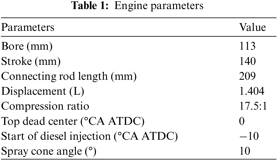
In this study, in order to investigate the effect of a wider range of AER on ADDF engine performance, the study was conducted with the help of relevant experimental data, and a DK32 small-bore four-stroke diesel engine was used as the object of the study to simulate the effect of AER from 0% to 80% on the ADDF engine. In addition, the diesel spray tilt angle (angle of the oil beam and the z-axis in the xz plane), as shown in Fig. 1b. The effect of spray tilt angle on the performance of the ADDF engine was investigated at an AER of 60%. The purpose was to achieve better combustion characteristics with lower emissions by adjusting the spray tilt angle. It provides some theoretical value for the ADDF engine widely used in the transportation field.
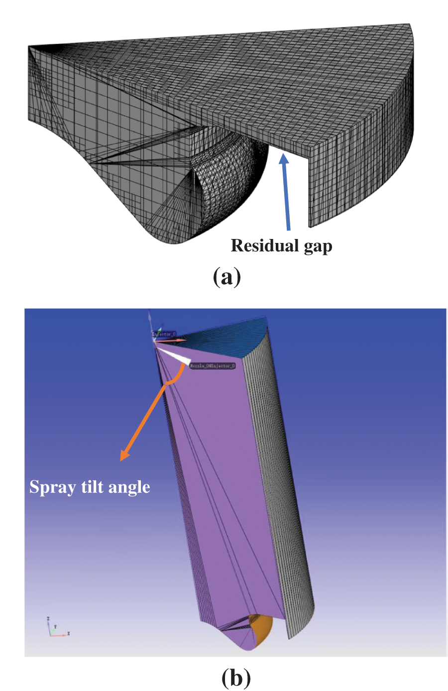
Figure 1: CFD grid model (a) and geometric model (b)
2 Numerical Simulation Methods
2.1 Simulation Methods and Geometric Models
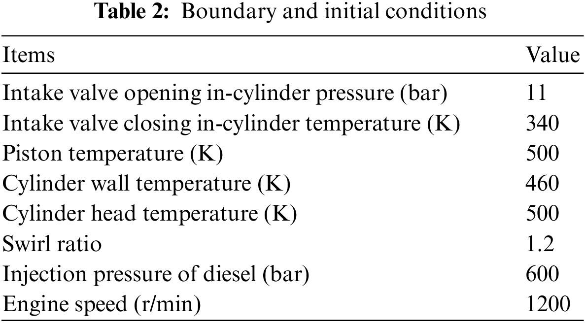
A DK32 single-cylinder engine model with a bore of 113 mm was used. Detailed engine parameters are shown in Table 1. The engine performance was calculated using the 3D Computational fluid dynamic (CFD) simulation software CONVERGE V3.0. In the simulation, ammonia was mixed with air and added to the cylinder and then the mixture was ignited by high-pressure injection of diesel fuel. The model prototype injector nozzle was seven-hole shaped, and the nozzle interval angle was 51.4°. Considering the calculation time of the simulation, the one-seventh sector model of the engine was used for the calculation, which saves time and ensures the calculation accuracy. The engine simulation computational grid model in Fig. 1a and geometric model are shown in Fig. 1b.
Simulations require the use of appropriate sub-models for the description of their complex physico-chemical processes. This study used a transient chemical kinetic SAGE combustion model that can be accurately calculated by fully utilizing the primitive reaction data. The Renormalization Group (RNG)k-
2.3 Boundary and Initial Conditions
The main simulation boundary and initial conditions of the engine are summarized in Table 2.
2.4 Definition of Simulation Characterization Parameters
The low heating value (LHV) of diesel fuel is 43.4 MJ/kg and that of ammonia is 18.6 MJ/kg [15]. CA10, CA50, and CA90 represent the crank angle (CA) at 10%, 50%, and 90% of total in-cylinder fuel heat release, respectively. The combustion duration is the crank angle interval from CA10 to CA90. The AER and ITE are sourced in Eqs. (1) and (2).
where
Where
In order to accurately simulate the ammonia-diesel dual-fuel combustion process, the mechanism was verified using modified combustion test data based on diesel engines as well as geometric modeling by Yousefi et al. [15]. The diesel substitution mechanism was derived from the N-Dodecane Skeletal mechanism developed by Frassoldati et al. [28] containing 993 radical reactions of 96 components. The ammonia combustion mechanism was derived from the improved mechanism of Otomo et al. [29] research containing 213 radical reactions of 32 components, which was derived from the mechanism developed by Song et al. [30]. The research members of this paper used CHEMKIN to merge the selected mechanisms and adjusted for duplicate radical reactions to generate an ammonia-diesel combustion mechanism containing 109 components with 1079 radical reactions. A comparison of cylinder pressure and heat release rate was carried out at 0% and 40% ammonia energy ratio and the validation results were given. As can be seen in Fig. 2, the cylinder pressure curves accurately coincide with each other. The peak of the heat release rate was slightly different, and the curve’s overall trend was consistent, which verified the credibility of the ammonia-diesel reaction mechanism used in this study.
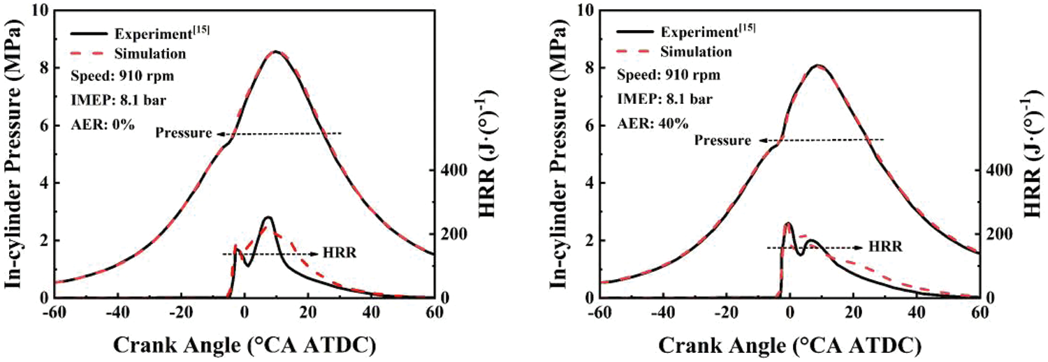
Figure 2: Validation of cylinder pressure and heat release rate
3.1 Effects of Ammonia Energy Ratio
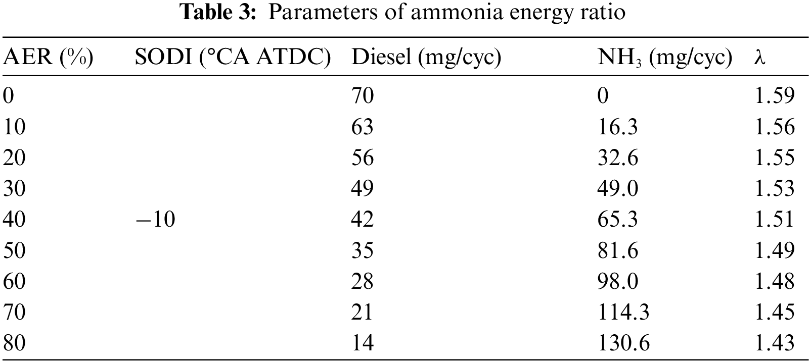
In engines, increasing ammonia energy reduces carbon dioxide (CO2) emission while contributing to NOx production. Setting a lower diesel injection and increasing the proportion of ammonia in the mixture to achieve a higher ammonia energy ratio. When the ammonia in the cylinder was increased, the amount of diesel fuel injected was decreased accordingly so that the total energy of ammonia and diesel fuel were equalized. The duration of diesel injection was 12°CA and the spray tilt angle was 75° in pure diesel mode. Maintaining the injection timing unchanged (−10°CA ATDC) during the increased AER, and maintaining the injection pressure unchanged by shortening the diesel injection duration when the AER was increased. Also, in the research on the effect of AER on ADDF engine performance, the diesel fuel spray tilt angle was kept at 75°. The parameters for the AER are shown in Table 3.
3.1.1 Combustion Performance at Different Ammonia Energy Ratio
As shown in Fig. 3a, as the AER was increased, the peak cylinder pressure and peak premixed heat release showed an increasing and then decreasing trend, and higher than the pure diesel mode at AER of 60%. The appearance of the peak premixed heat release was delayed with increasing AER. The increase in NH3 in the mixture increased the total amount of fuel in the cylinder at compression ignition, which promoted premixed combustion, but at the same time delayed the timing of ignition due to the higher ignition temperature of ammonia. In addition, diffusion combustion was weakened by the slower flame speed of ammonia. The peak diffusion heat release showed a decreasing trend with the rise of AER from 0% to 60%, and the engine combustion performance declined when the AER was higher than 60%. As shown in Figs. 3a and 3c, at an AER of 80%, the peak cylinder pressure and the peak premixed heat release were decreased dramatically, and significant delays were observed in CA10, CA50, and CA90. A large amount of ammonia was not ignited during premixed combustion due to insufficient diesel fuel injection, and the peak diffusion heat release was elevated due to the large amount of ammonia still present in the cylinder. Fig. 3b shows that the peak average temperature in the cylinder was increased and then decreased with the rised of AER, and the peak average temperature reached the maximum value of about 1900 K when the AER was 60%. The pressure rising rate and average temperature rising rate at AER of 40% and 60% are greater than that of the pure diesel mode, which suggests that the increased combustion rate at AER in this range results in rapid heat release. The extremely low In-cylinder average temperature indicates incomplete combustion at an AER of 80%. In Fig. 3c, the timing of Initial combustion was delayed backward with the rised of AER.
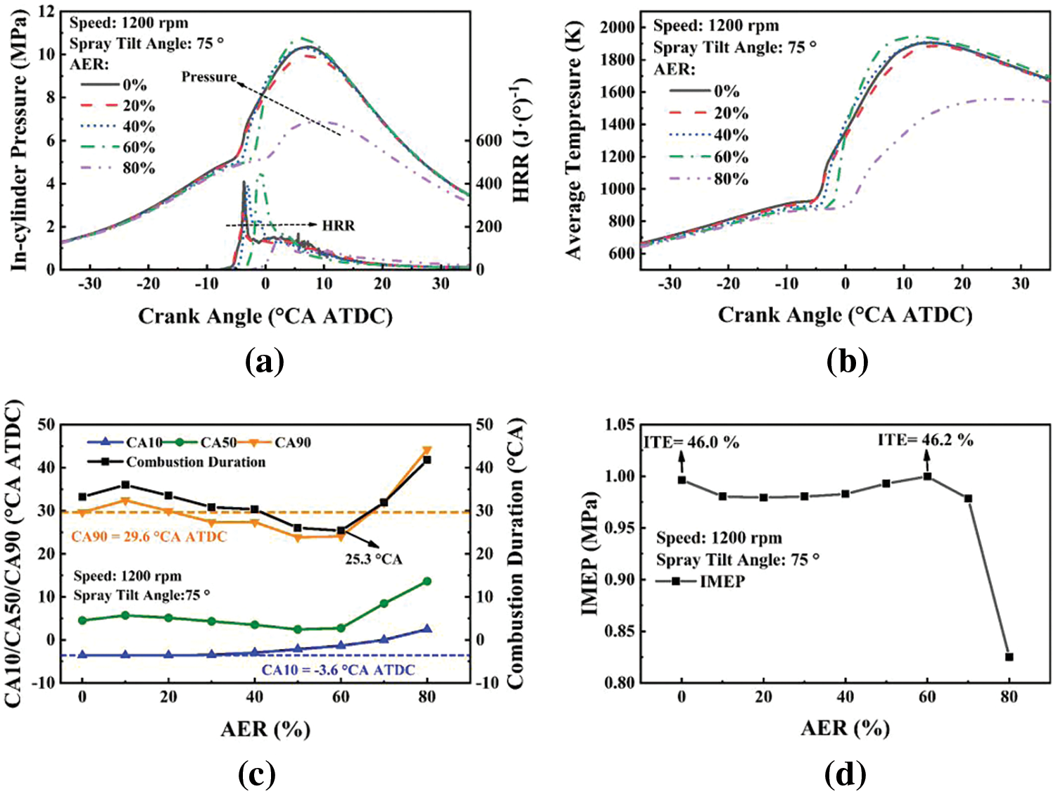
Figure 3: Effect of ammonia energy ratio on pressure, HRR (a), average temperature (b), CA10/CA50/CA90, combustion duration (c), and IMEP (d) with a spray flit angle of 75°
The increase in AER from 20% to 60% caused a delay in CA10 due to the high ignition temperature of the ammonia and an advance in both CA50 and CA90. The reason is that the increase in ammonia concentration in the cylinder mixture during the early phase of combustion allows more fuel to participate in the combustion, and the abundance of fuel accelerates the combustion rate and offsets the effect of the lower flame propagation rate of ammonia. It suggests that an increase in AER may concentrate the heat release more, resulting in an earlier CA50/CA90 and a shorter combustion duration. The combustion duration was gradually shortened with the rise of AER up to 60%, reaching a minimum value of 25.4°CA at AER of 60%. 7.8°CA was shortened compared to the pure diesel mode at an AER of 60%. The combustion process at 60% AER was analyzed in Section 3.1.3. However, when the AER was 10% and 20%, the CA50, CA90, and combustion duration were higher than those in pure diesel mode, which may be attributed to the fact that ammonia in the mixture was too dilute to weaken the flame propagation. In Fig. 3d, both Indicated Mean Effective Pressure (IMEP) and ITE exceed the pure diesel mode at an AER of 60%. This means that in this engine, a suitable AER contributed to engine combustion. The best combustion was achieved at an AER of 60% when the ITE reached a maximum value of 46.2%, which was an increase of 0.2% compared to the pure diesel mode ITE value of 46.0%. The rapid decrease in IMEP and ITE at AER above 70% and the lowest values at AER of 80% suggests that poor combustion can result from higher AER.
3.1.2 Emissions Performance at Different Ammonia Energy Ratio
Fig. 4a shows that unburned ammonia emission was rised with increasing AER. Analyzed in conjunction with Figs. 3a and 3d, the diffusion combustion temperature in the cylinder was decreased when the AER rised, and more NH3 was not ignited, which also lead to a shorter combustion duration with an increase in the AER within a certain range (10%–60%). At an AER of 80% unburned ammonia emission reached a maximum value of 28.6 mg/cyc, but due to unsatisfactory combustion at this point, the combustion duration was extended to 41.7°CA. The variation of nitrogen dioxide (NO2) emission with rised AER showed two inflection points at AER 40% and AER 60%, respectively, and the emission of NO2 was maximum at pure diesel mode and minimum at AER of 80%. Fig. 4b shows that NO emission reached a maximum value of 2.2 mg/cyc in pure diesel mode. The NO emission appeared to be 2.1 mg/cyc at 60% AER, which was slightly lower than in pure diesel mode. The reason for the larger NO emission was that the combustion was better at 60% AER and the heat release was more concentrated. The high-temperature area in the cylinder was larger, the N2O was easy to be decomposed in the high-temperature environment to produce a large amount of NO. In addition, more ammonia involved in combustion at rised AER up to 60% was also a significant contributor to NO emission. From Fig. 4b, it can be seen that N2O emission showed a minimum value of 0.28 mg/cyc at an AER of 60%. At 80% AER, N2O emission reached a maximum value of 0.76 mg/cyc due to poor combustion and low average in-cylinder temperature. Analyzed in conjunction with Fig. 4c, as the AER rised, the reduction in diesel fuel supply decreased CO2 emission, but N2O emission was increased due to a larger supply of NH3. The GHG was caused by N2O was 300 times more than CO2, which was detrimental to the reduction of GHG emissions. GHG was obtained by synthesizing the effects of N2O and CO2 on the greenhouse effect. The results of the study showed that AER in the range of 50%–70% in this model can achieve the reduction of GHG emissions. The GHG emissions reached a minimum value of 168.9 mg/cyc at an AER of 60%, which was a 22.3% decrease in GHG emissions relative to the pure diesel mode of 217.1 mg/cyc. In Fig. 4d, CO and Hydrocarbon (HC) emissions were kept low in pure diesel mode. The lower combustion efficiency and in-cylinder temperature of the ADDF mode resulted in consistently higher CO and HC emissions than the pure diesel mode at AERs below 40%. The lower average in-cylinder temperature resulted in higher CO emission at 10%. As the AER was increased from 10% to 40%, the CO emission was decreased gradually with decreasing diesel injection, which was related to the carbon originating from the diesel and the increase of in-cylinder temperature. At AER of 40%–60%, the lag in the moment of ignition and the shortening of the combustionduration lead to an increase in CO emission. The CO emission was 0.74 mg/cyc and HC emission was 0.0036 mg/cyc at AER of 60%. When the AER was higher than 60%, despite the small diesel injection, the CO emission was still higher than that of the pure diesel mode, while HC was increased substantially with the increase of ammonia, which was an indication of incomplete combustion of ammonia.
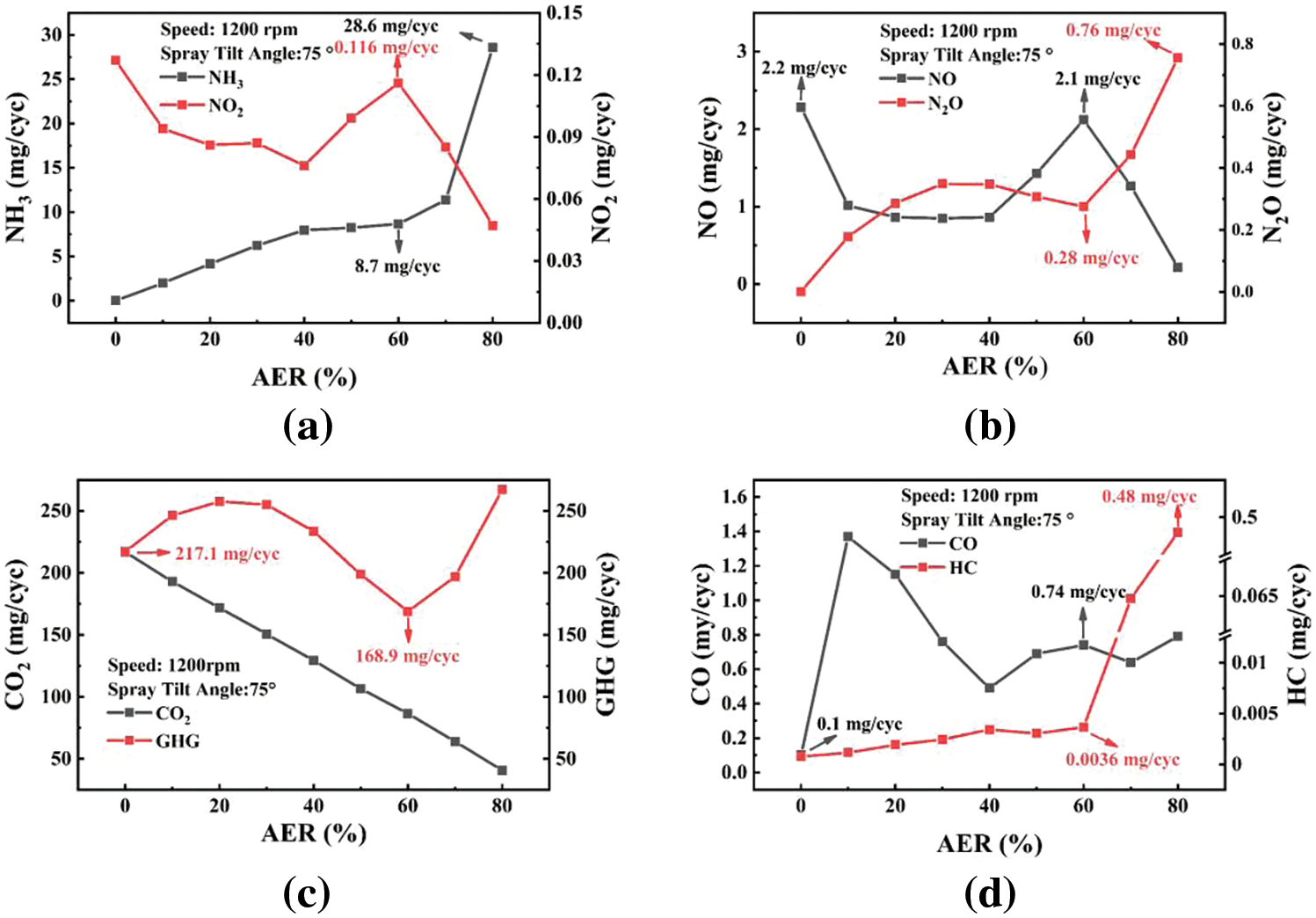
Figure 4: Effect of ammonia energy ratio on NH3, NO2 emissions (a), NO, N2O emissions (b), CO2, GHG emissions (c) and CO, HC emissions (d) with an spray flit angle of 75°
3.1.3 Combustion Process Analysis
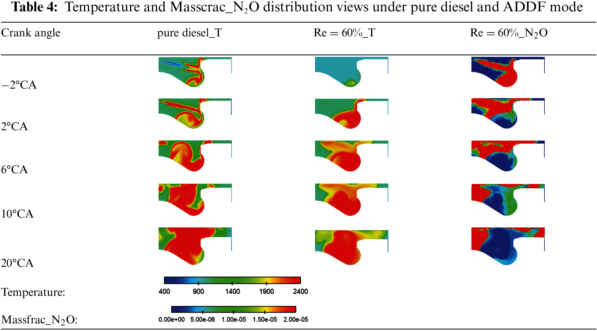
Table 4 shows the in-cylinder temperature change in pure diesel mode and 60% AER (ADDF mode), and the N2O distribution views at 60% AER. Due to ammonia fuel characteristics, the unburned area temperature of ADDF mode was significantly lower than pure diesel mode. From Fig. 3c, the combustion initiation timing is −3.5°CA ATDC for pure diesel fuel and −1.3°CA ATDC for 60% AER. Combustion had already begun at −2°CA ATDC in pure diesel mode when the ADDF mode had not yet begun combustion. Due to the lower concentration of O2 and higher concentration of NH3 in the mixture gas, and the lower temperature in the cylinder, the combustion initiation timing was delayed. The delay of the combustion initiation timing in the ADDF mode favored the diffusion of diesel in the mixture gas. The mixing of ammonia and diesel was better resulted in a higher heat release rate in the initial phase of the ADDF mode than in the pure diesel mode. As shown in the Table 4, Crank Angle at 2°CA ATDC, 6°CA ATDC, and 10°CA ATDC, the heat release of ADDF mode was more concentrated, and the high-temperature region was significantly larger than that of pure diesel mode, which contributed to a shorter combustion duration at an AER of 60%. In addition, at 20°CA ATDC, the high-temperature region temperature of the ADDF mode was less than that of the pure diesel mode because the combustion of the ADDF mode was already near its end. Pure diesel mode combustion produced almost no N2O emission. From the ADDF model Masscrac_N2O distribution views, it can be seen that ammonia produced a large amount of N2O immediately at the beginning of combustion, the region of N2O production was mainly in the low-temperature region of the ammonia reaction, and it was almost nonexistent in the high-temperature region. Therefore, it is necessary to adopt strategies to raise the in-cylinder temperature and reduce the range of the low-temperature area to reduce the emissions of N2O and GHG in ADDF engines.
3.2 Effects of Spray Tilt Angle
In this section, the effect of diesel fuel spray tilt angle on engine performance was investigated based on an AER of 60%. The spray tilt angle was used from 57.5° to 87.5° in 2.5° steps. The objective was to investigate the effect of spray tilt angle on the performance of the ADDF engine and to achieve high thermal efficiency with low emissions by adjusting the spray tilt angle. The results of ITE and GHG emissions are shown in Fig. 5. ITE is less than 45% and GHG emissions are higher outside the spray tilt angle from 65° to 85°, which reduces engine performance. Moreover, it has been representative of the effect of spray tilt angle in the range of 65° to 85°. Therefore, the spray tilt angle from 65° to 85° was selected for further study.
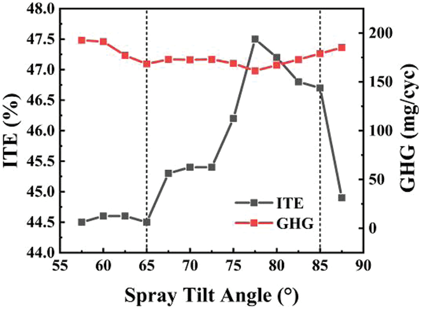
Figure 5: Effect of spray tilt angle on ITE and GHG with an AER of 60%
3.2.1 Combustion Performance at Different Spray Tilt Angles
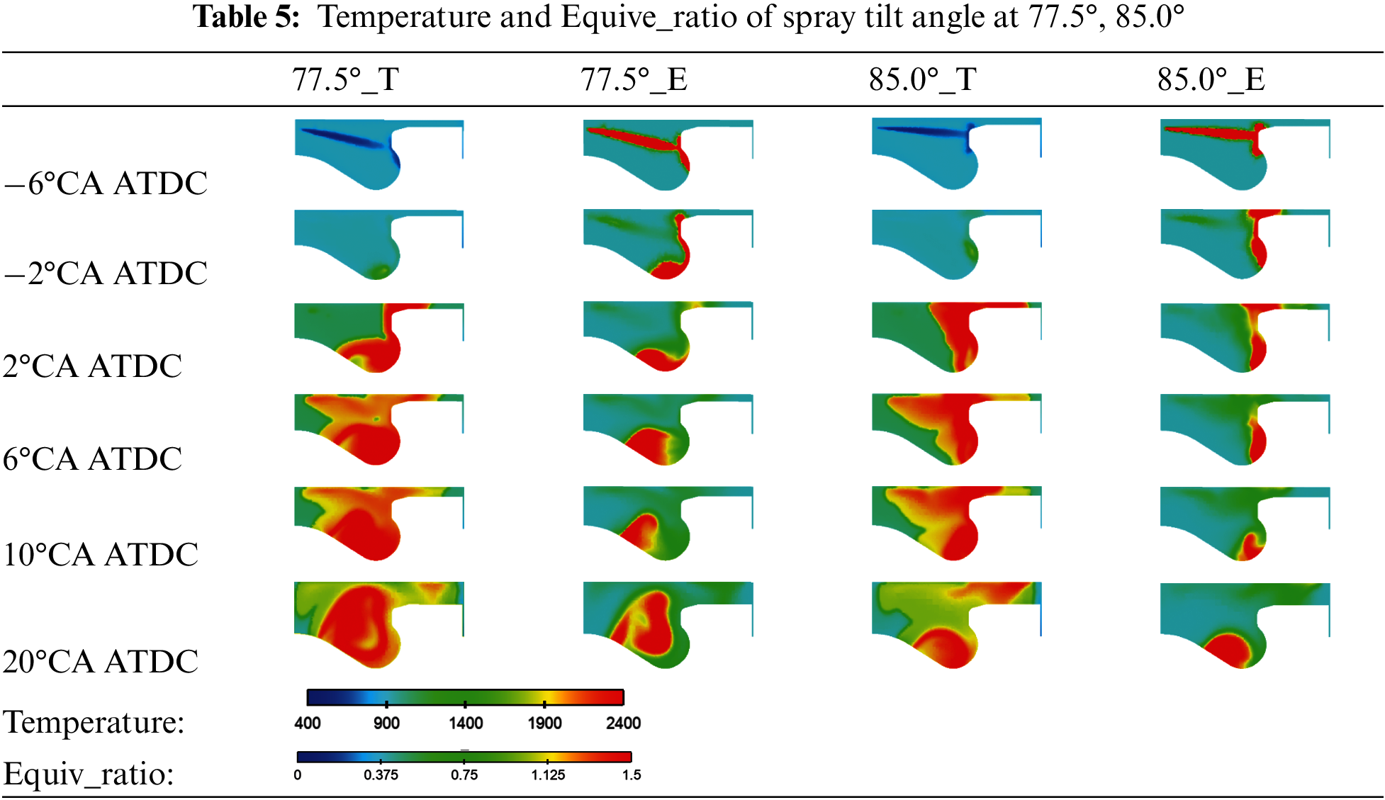
In Fig. 6a, as the spray tilt angle was increased, the peak cylinder pressure showed an increasing and then decreasing trend, while the peak premixed heat release showed a decreasing and then increasing trend, and the appearance of the peak premixed heat release was delayed backward. Peaks cylinder pressure and premixed heat release were highest at a spray tilt angle of 80°. It can be seen that a spray tilt angle of about 80° was conducive to improving the combustion performance of the ADDF engine. Relative to a spray tilt angle of 75° (spray tilt angles in the range of 65°–80°), the peak premixed heat release was increased regardless of whether the spray tilt angle was increased or decreased. When the spray tilt angle was lower than 75°, the oil beam shot to the upper wall of the piston bowl and swung back clockwise along the wall, the rapid diffusion of diesel fuel enhanced the heat release rate during premixed combustion. When the spray tilt angle was higher than 75°, the oil beam was cut by the residual gap edge and the bowl edge, the ammonia in the residual gap participated in the combustion for the first time, which led to an increase in the heat release rate. Fig. 6b is the average temperature in the cylinder with the spray tilt angle changing curve. As the spray tilt angle was increased, the amount of ammonia in the residual gap that participated in combustion increased. with the increase of the spray tilt angle, shows a trend of first increasing and then decreasing. At a spray tilt angle of 80°, the average temperature can reach about 2000 K. However, when the spray tilt angle was increased from 80° to 85°, the diffusion of diesel was weakened leading to a decrease in the average temperature. Fig. 6c indicates that CA10 and CA50 were basically unchanged at different spray tilt angles. At a spray tilt angle of 65°, the combustion duration was shortened due to the advancement of CA90. Analyzed in conjunction with Figs. 6d and 7a, the diesel beam was sprayed to the bottom of the piston bowl because the spray tilt angle was too small. A large amount of ammonia gas exists in the residual gap between the piston and the cylinder head that was not ignited, and combustion ends prematurely, which leads to a shorter combustion duration. Combustion duration at a spray tilt angle of 77.5° was also shortened to 24.2°CA. In Table 5, combined with the equivalent ratio and temperature distribution views, the shortening of the combustion duration was due to the better diffusion of diesel in the cylinder when the spray tilt angle was 77.5°. Diesel fuel became evenly distributed in the residual gap and piston bowl, At which time the fuel mixture’s formation in the cylinder was more homogeneous, so the combustion effect was better. When the spray tilt angle was increased to 85°, a large amount of diesel fuel entered the residual gap, and the diesel in the piston bowl was less. It cut the rate of combustion in the piston bowl. Although the combustion of ammonia was ultimately more complete, The combustion of large quantities of fuel mixtures in small spaces in the residual gap made it difficult for the flame to spread in time. The slower flame speed of ammonia resulted in a longer combustion duration. Fig. 6d shows the variation of ITE with spray tilt angles. The ITE value reached a maximum of 47.5% at a spray tilt angle of 77.5°, an increase of 1.5% compared to the pure diesel mode with a spray tilt angle of 75°. With a slightly higher spray tilt angle, more diesel fuel spread into the cylinder gap, and ammonia with its high ignition temperature and low flame propagation speed was more easily ignited. In addition, the 60% energy fraction of ammonia provided a high mixture concentration in the cylinder during the combustion start-up phase. More fuel is involved in the combustion at this stage. At this time, the combustion duration was shortened, the heat release was more concentrated, the HRR was raised, and The ITE was increased .
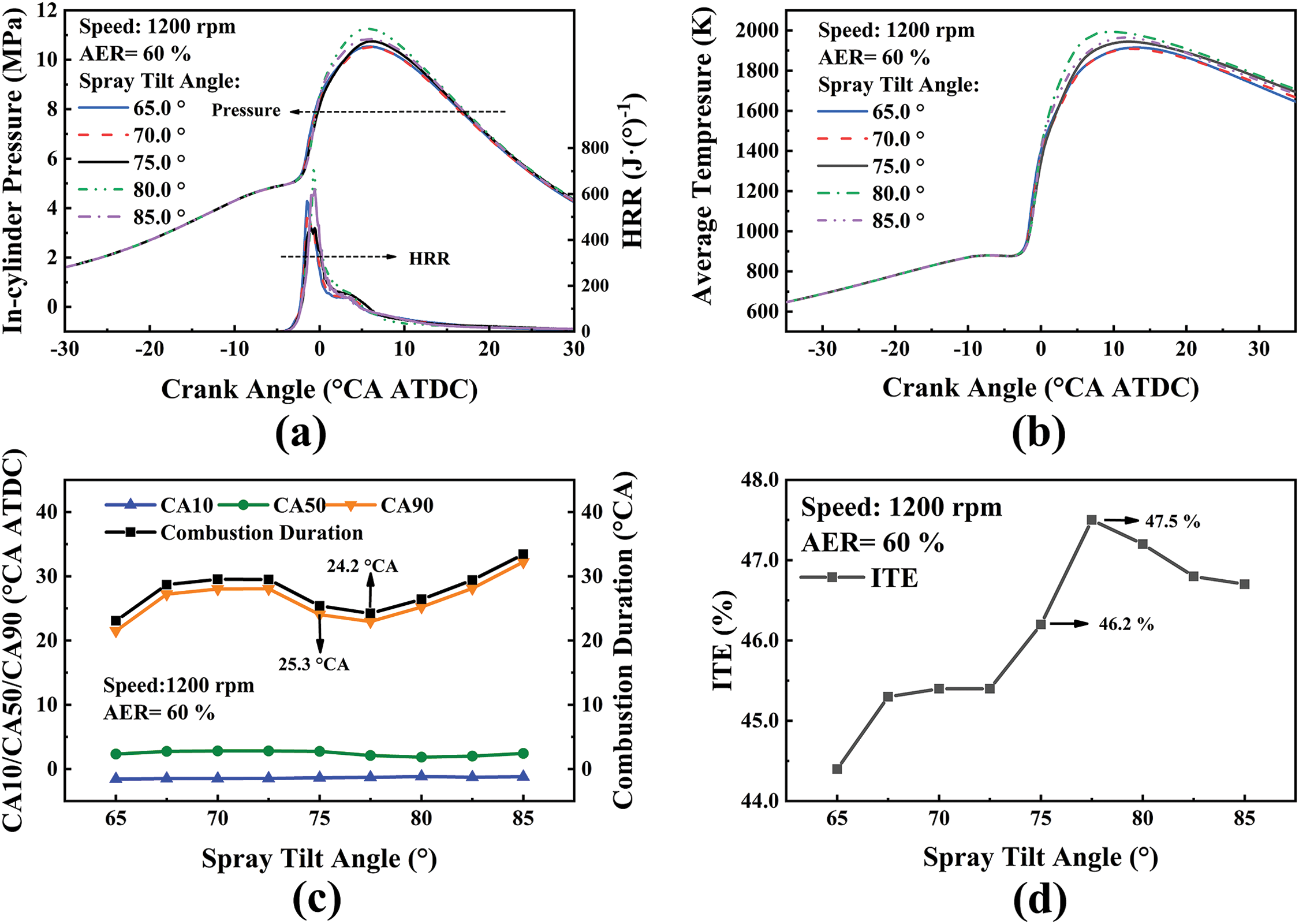
Figure 6: Effect of spray tilt angle on pressure, HRR (a), average temperature (b), CA10/CA50/CA90, combustion duration (c), and ITE (d) with an AER of 60%
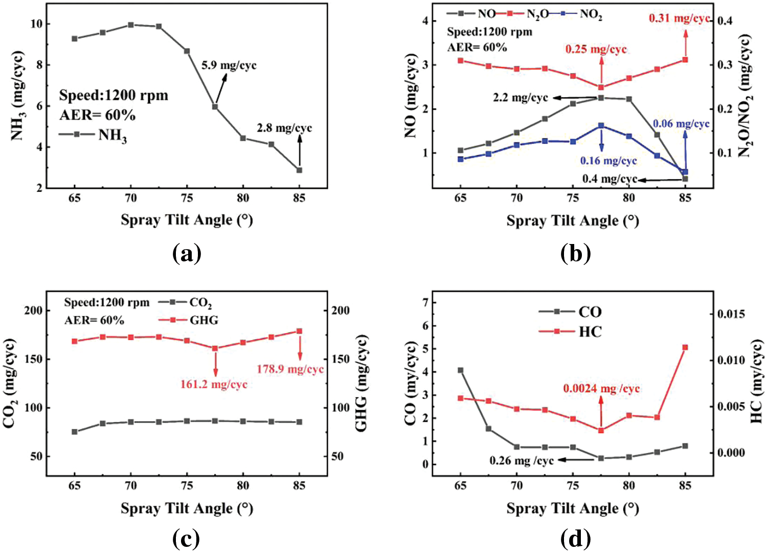
Figure 7: Effect of spray tilt angle on NH3 emission (a), NO, NO2, N2O emissions (b), CO2, GHG emissions (c) and CO, HC emissions (d) with an AER of 60%
3.2.2 Emissions Performance at Different Spray Tilt Angles
It can be seen in Fig. 7a, that there was a small increase in unburned ammonia emission when the spray tilt angle was increased from 65° to 70°, with a maximum of unburned ammonia emission at 70°. As the spray tilt angle continued to increase from 70°, the unburned ammonia emission began to decrease and reached a minimum value of 2.8 mg/cyc at 85°, which indicates that a larger spray tilt angle favored ammonia combustion. The narrow space in the residual gap and the low flame propagation speed of ammonia can lead to incomplete or insufficient combustion. The increase in spray tilt angle increases the quantity of diesel entering the residual gap and prolongs the combustion duration. It is not conducive to the formation of high-temperature areas during the combustion process. In Fig. 7b, the emissions of N2O and NO showed an opposite trend with the changing of spray tilt angle, the former was decreased and then increased, and the latter was increased and then decreased, with the increase of spray tilt angle. At a spray tilt angle of 77.5°, N2O emission reached a minimum value of 0.25 mg/cyc, while NO emission reached a maximum value of 2.2 mg/cyc. There were two reasons for this result. On the one hand, the average indicated in-cylinder temperature was higher when the spray tilt angle was increased to 77.5° relative to 75° (Fig. 6b). The increase of in-cylinder temperature caused more N2O to be oxidized and decomposed to produce NO. On the other hand, more NH3 involved in combustion also increased NO emission. The increase of spray tilt angle from 75° to 77.5° reduced N2O emission by 9.4% per cycle, while NO emission increased by 6.3% per cycle. NO2 emission was also maximized at a spray tilt angle of 77.5°. Fig. 7c shows that CO2 emission was lowest at a spray tilt angle of 65°, where combustion ends prematurely resulting in incomplete diesel combustion. The spray tilt angle continued to increase (from 67.5%–85%), and CO2 emission remained stable because the quantity of diesel fuel injected per cycle did not change. With a spray tilt angle of 77.5°, GHG emissions reached a minimum value of 161.2 mg/cyc due to the reduction of N2O emission, which was 25.7% lower than the GHG emissions of 217.1 mg/cyc in pure diesel mode with a spray tilt angle of 75°. As can be seen in Fig. 7d, when the spray tilt angle was less than 75°, the emissions of CO and HC were increased, especially at 65°, the low ITE was an indicator of very high CO emission. When the spray tilt angle was 77.5°, the increase in average in-cylinder temperature reduced the generation of CO and HC, the emissions of CO and HC at this time were 0.26 and 0.0024 mg/cyc, which were 64.8% and 33.3% lower than the emissions of CO and HC at 75°, respectively. As the spray tilt angle was increased from 77.5°, the CO and HC emissions were increased with decreasing ITE. At a spray tilt angle of 85°, Ammonia in the residual gap was more easily ignited, but the narrow space did not provide an environment for further HC combustion. It can be seen that low combustion temperatures increase CO and HC emissions while decreasing ITE. insufficient combustion of ammonia generates large amounts of HC.
This study investigated the effect of AER (0%–80%) on engine performance and the spray tilt angle on combustion and emissions at an AER of 60%. Based on the simulation results, the conclusions are summarized as follows:
1. The results of investigating the effect of AER showed that an AER below 50% was detrimental to the overall engine performance. Relative to pure diesel mode, AER in 50% to 70% could reduce GHG emissions. GHG emissions were reduced by 22.3% and ITE was increased by 0.2% at an AER of 60%. It significantly reduced the engine performance at 80% AER. NO and NO2 emissions were decreased with increased AER while unburned ammonia emission was increased. The CO and HC emissions in ADDF mode were always higher than those in pure diesel mode. In higher AER conditions, HC emission was significantly increased.
2. In the ADDF engine, increasing AER reduced the CO2 emission and increased the N2O emission, which led to the GHG emissions were not always reduced. The N2O is almost absent in high-temperature regions. Increasing the in-cylinder combustion temperature or the area of the high-temperature region can effectively reduce N2O and GHG emissions. At the same time, it will increase the emission of NO.
3. Based on the AER of 60%. The results of adjusting the spray tilt angle showed that a larger spray tilt angle helped the ammonia in the residual gap to participate in the combustion. The unburned ammonia emission reached a minimum value of 2.8 mg/cyc when the spray tilt angle was 85°. Compared to the spray tilt angle of 75° condition, the unburned ammonia emission was reduced by 66.9%, the ITE was increased by 0.6%, and NO emission was reduced by 80% at a spray tilt angle of 85°. However, N2O and CO emissions were increased, leading to a slight increase in GHG emissions, and HC emission was significantly increased when the spray tilt angle of 85°.
4. When the AER was 60% and the spray tilt angle was 77.5°, the engine exhibited the best overall performance, with the ITE reaching 47.5%. Compared to the pure diesel mode with a 75° spray tilt angle, The ITE was increased by 1.5%, the GHG emissions were reduced by 25.7%. Furthermore, when the spray tilt angle was increased from 75° to 77.5° (AER was 60%), the unburned ammonia emission was reduced by 31%, CO emission was reduced by 64.8%, and HC emission was reduced by 33.3%. These results indicate that adjusting the diesel spray tilt angle can improve the ADDF engine performance and reduce unburned ammonia emission. This study enhanced ADDF engine performance by adjusting the spray tilt angle, which helps in the low-cost conversion of diesel engines to ADDF engines and provides theoretical guidance for the application of ADDF engines.
Acknowledgement: None.
Funding Statement: The authors received no specific funding for this study.
Author Contributions: The authors confirm their contribution to the paper as follows: Zhifeng Zhao is the first author, responsible for writing the main content of the outline. Xuelong Miao is the corresponding author, responsible for maintaining contact with the magazine. Xu Chen and Yage Di conceived and designed the study. Zhenjie Bao and Zhuo Yang are responsible for model design and revision. Zhifeng Zhao and Xu Chen collected and analyzed the data. Jinbao Zheng summarized the main conclusions.
Availability of Data and Materials: The data that support the findings of this study are available from the corresponding author, Xuelong Miao, upon reasonable request.
Conflicts of Interest: The authors declare that they have no conflicts of interest to report regarding the present study.
References
1. B. Wang, C. Yang, H. Wang, D. Hu, and Y. Wang, “Effect of diesel-ignited ammonia/hydrogen mixture fuel co mbustion engine combustion and emission performance,” Fuel, vol. 33, no. 2, pp. 125865, 2023. [Google Scholar]
2. C. M. White, R. R. Steeper, and A. E. Lutz, “The hydrogen-fueled internal combustion engine: A technical review,” Hydro. Energy, vol. 31, no. 10, pp. 1292–1305, Aug. 2006. [Google Scholar]
3. P. Dimitriou and R. Javaid, “A review of ammonia as a compression ignition engine fuel,” Int. J. Hydro. Energy, vol. 45, no. 11, pp. 7098–7718, Feb. 2020. doi: 10.10.1016/j.ijhydene.2019.12.209. [Google Scholar] [CrossRef]
4. C. Kurien and M. Mittal, “Review on the production and utilization of green ammonia as an alternate fuel in dual-fuel compression ignition engines,” Energy Convers. Manage., vol. 251, no. 1, pp. 114990, Jan. 2022. [Google Scholar]
5. J. T. Gray, “Ammonia fuel-engine compatibility and combustion automotive engineering congress exposition,” SAE Inter., vol. 75, no. 1, pp. 785–807, 1967. [Google Scholar]
6. G. C. Garabedian and J. H. Johnson, The Theory of Operation of an Ammonia Burning Internal Combustion Engine. Warren, MI, USA: Army Tank-Automotive Center, pp. 333–348, 1966. [Google Scholar]
7. E. S. Starkman, G. E. James, and H. K. Newhall, “Ammonia as a diesel engine fuel: Theory and application national fuels lubricants,” Nation. Fuel. Lubri., vol. 76, no. 4, pp. 3193–3212, 1967. [Google Scholar]
8. Y. Xia, G. Hashimoto, K. Hadi, N. Hashimoto, A. Hayakawa and H. Kobayashi, “Turbulent burning velocity of ammonia/oxygen/nitrogen premixed flame in O2-enriched air condition,” Fuel, vol. 268, no. 15, pp. 117383, May 2020. [Google Scholar]
9. S. M. Grannell, D. N. Assanis, and S. V. Bohac, “The fuel mix limits and efficiency of a stoichiometric, ammonia, and gasoline dual fueled spark ignition engine,” J. Eng. Gas Turb. Pow., vol. 130, no. 4, pp. 42802, May 2008. [Google Scholar]
10. K. Ryu, G. E. Zacharakis-Jutz, and S. C. Kong, “Effects of gaseous ammonia direct injection on performance characteristics of a spark-ignition engine,” Appl. Energy, vol. 113, no. 1, pp. 206–215, Mar. 2014. [Google Scholar]
11. R. C. Rocha, M. Costa, and X. S. Bai, “Chemical kinetic modelling of ammonia/hydrogen/air ignition, premixed flame propagation and NO emission,” Fuel, vol. 246, no. 15, pp. 24–33, Jun. 2019. [Google Scholar]
12. A. J. Reiter and S. C. Kong, “Combustion and emissions characteristics of compression-ignition engine using dual ammonia-diesel fuel,” Fuel, vol. 90, no. 1, pp. 87–97, Jan. 2011. [Google Scholar]
13. Y. Niki, Y. Nitta, H. Sekiguchi, and K. Hirata, “Emission and combustion characteristics of diesel engine fumigated with ammonia,” ,presented at the 2018 ASME Int. Combus. Engi. Div. Fall Tech. Conf., Large Bore Engines, Adv. Combustion, Nov. 2018, vol. 1. [Google Scholar]
14. Y. Niki, Y. Nitta, H. Sekiguchi, and K. Hirata, “Diesel fuel multiple injection effects on emission characteristics of diesel engine mixed ammonia gas into intake air,” Engi. Gas Turbi. Pow., vol. 141, no. 6, pp. 61020, Jun. 2019. [Google Scholar]
15. A. Yousefi, H. Guo, S. Dev, B. Liko, and S. Lafrance, “Effects of ammonia energy fraction and diesel injection timing on combustion and emissions of an ammonia/diesel dualfuel engine,” Fuel, vol. 314, no. 15, pp. 122723, Apr. 2022. [Google Scholar]
16. A. Yousefi, H. Guo, S. Dev, S. Lafrance, and B. Liko, “A study on split diesel injection on thermal efficiency and emissions of an ammonia/diesel dual-fuel engine,” Fuel, vol. 316, no. 15, pp. 123412, May 2022. [Google Scholar]
17. J. Liu and J. Liu, “Experimental investigation of the effect of ammonia substitution ratio on an ammonia-diesel dual-fuel engine performance,” J. Clean. Prod., vol. 434, no. 1, pp. 140274, Jan. 2024. [Google Scholar]
18. E. Nadimi, G. Przybyła, T. M. Lewandowski, and W. Adamczyk, “Effects of ammonia on combustion, emissions, and performance of the ammonia/diesel dual-fuel compression ignition engine,” J. Trans. Energy Ins., vol. 107, pp. 101158, Apr. 2023. [Google Scholar]
19. T. Li, X. Zhou, N. Wang, X. Wang, R. Chen and S. Li, “A comparison between low-and high-pressure injection dual-fuel modes of diesel-pilot-ignition ammonia combustion engines,” Energy Inst., vol. 102, pp. 362–373, Jun. 2022. [Google Scholar]
20. E. Nadimi, G. Przybyła, T. Løvås, G. Peczkis, and W. Adamczyk, “Experimental and numerical study on direct injection of liquid ammonia and its injection timing in an ammonia-biodiesel dual injection engine,” Energy, vol. 284, no. 1, pp. 129301, Dec. 2023. [Google Scholar]
21. Q. Huang and J. Liu, “Preliminary assessment of the potential for rapid combustion of pure ammonia in engine cylinders using the multiple spark ignition strategy,” Inter. J. Hydro. Energy, vol. 55, no. 15, pp. 375–385, Feb. 2024. [Google Scholar]
22. Z. Han and R. D. Reitz, “Turbulence modeling of internal combustion engines using RNG κ-ε models,” Combus Scien. Tech., vol. 106, no. 4–6, pp. 267–295, Jan. 1995. [Google Scholar]
23. A. A. Amsden, “A computer program for chemically reactive flows with sprays,” Nasa Sti/recon. Tech. Report. N., vol. 5, no. 4, pp. 107–113, May 1989. doi: 10.10.2172/6228444. [Google Scholar] [CrossRef]
24. J. C. Beale and R. D. Reitz, “Modeling spray atomization with the kelvin-helmholtz/rayleigh-taylor hybrid model,” Atomiz. Spray., vol. 9, no. 6, pp. 623–650, 1999. doi: 10.10.1615/AtomizSpr.v9.i6.40. [Google Scholar] [CrossRef]
25. D. P. Schmidt and C. J. Rutland, “A new droplet collision algorithm,” J. Computa. Physi., vol. 164, no. 1, pp. 62–80, Oct. 2000. [Google Scholar]
26. P. J. O’Rourke and A. A. Amsden, “A spray/wall interaction submodel for the KIVA-3 wall film model,” SAE Transac., vol. 109, no. 3, pp. 281–298, Jan. 2000. [Google Scholar]
27. H. Chen, J. He, and H. Hua, “Investigation on combustion andemission performance of a common rail diesel engine fueled withdiesel/biodiesel/polyoxymethylene dimethyl ethers blends,” Energy Fuels, vol. 31, no. 11, pp. 11710–11722, Sep. 2017. [Google Scholar]
28. A. Frassoldati, G. D’Errico, and T. Lucchini, “Reduced kinetic mechanisms of diesel fuel surrogate for engine CFD simulations,” Combus. Fla., vol. 162, no. 10, pp. 3991–4007, Oct. 2015. [Google Scholar]
29. J. Otomo, M. Koshi, and T. Mitsumori, “Chemical kinetic modeling of ammonia oxidation with improved reaction mechanism for ammonia/air and ammonia/hydrogen/air combustion,” Inter. J. Hydro. Energy, vol. 43, no. 5, pp. 3004–3014, Feb. 2018. [Google Scholar]
30. Y. Song, H. Hashemi, and J. M. Christensen, “Ammonia oxidation at high pressure and intermediate temperatures,” Fuel, vol. 181, no. 1, pp. 358–365, Oct. 2016. [Google Scholar]
Cite This Article
 Copyright © 2024 The Author(s). Published by Tech Science Press.
This work is licensed under a Creative Commons Attribution 4.0 International License , which permits unrestricted use, distribution, and reproduction in any medium, provided the original work is properly cited.
 Downloads
 Citation Tools