
 Submit a Paper
 Propose a Special lssue
 Open Access
ARTICLE

Regenerative Braking Energy Recovery System of Metro Train Based on Dual-Mode Power Management
School of Automation and Electrical Engineering, Lanzhou Jiaotong University, Lanzhou, 730070, China
* Corresponding Author: Xiaotong Zhu. Email:
Energy Engineering 2024, 121(9), 2585-2601. https://doi.org/10.32604/ee.2024.049762
Received 17 January 2024; Accepted 30 April 2024; Issue published 19 August 2024
 View Full Text
 Download PDF
Abstract
In order to fully utilize the regenerative braking energy of metro trains and stabilize the metro DC traction busbar voltage, a hybrid regenerative braking energy recovery system with a dual-mode power management strategy is proposed. Firstly, the construction of the hybrid regenerative braking energy recovery system is explained. Then, based on the power demand of low-voltage load in metro stations, a dual-mode power management strategy is proposed to allocate the reference power of each system according to the different working conditions, and the control methods of each system are set. Finally, the correctness and effectiveness of the dual-mode strategy are verified through simulation, and the proposed braking energy utilization scheme is compared with other single-form utilization schemes. The results illustrate that the hybrid system with the dual-mode strategy can effectively recycle the regenerative braking energy of metro train and inhibit the busbar voltage fluctuation; the proposed braking energy utilization scheme has certain advantages on energy recovery and DC bus voltage stabilization compared with other single-form schemes; the proposed power management strategy can correctly allocate the reference power of each system with a lower construction cost.Graphic Abstract

Keywords
Nomenclature
| The energy required by the train when a metro train is in traction operation (J) | |
| The energy provided by the traction substation (J) | |
| The braking energy which is returned to the DC bus (J) | |
| The braking energy which is consumed by the braking resistor (J) | |
| The braking energy stored by the energy-storage system (J) | |
| The braking energy returned to the AC 400 V grid by the energy feedback system (J) | |
| The power consumed when the train starts up (MW) | |
| The power consumed by the train braking resistor (MW) | |
| The power stored by the energy-storage system (MW) | |
| The power fed back to the low voltage load (MW) | |
| The power required to start the train under traction condition (MW) | |
| The power returned to the distribution network under regenerative braking condition (MW) | |
| SOC | The state of charge |
| The maximum value of SOC | |
| The minimum value of SOC | |
| The voltage of the DC busbar (V) | |
| The discharge voltage threshold of the energy storage device (V) | |
| The charge voltage threshold of the energy storage device (V) | |
| The maximum discharging power of the energy-storage system (MW) | |
| The maximum charging power of the energy-storage system (MW) | |
| The maximum power of the energy-feedback system (MW) | |
| The reference power of energy-storage system (MW) | |
| The reference power of energy-feedback system (MW) | |
| The reference voltage of energy-storage system in energy-storage system control block diagram (V) | |
| The limit value of the reference current in energy-storage system control block diagram (A) | |
| The d-axis component of the low-voltage load’s voltage in energy-feedback system control block diagram (V) | |
| The active power current threshold in energy-feedback system control block diagram (A) | |
| The active current reference value (A) | |
| The reactive current reference value (A) | |
| The active current components of three-phase current in the low-voltage system (A) | |
| The reactive current components of three-phase current in the low-voltage system (A) | |
| The voltage active component (V) | |
| The voltage reactive component (V) | |
| The voltage component transformed by | |
| The voltage component transformed by |
With greenhouse gas emissions and fossil energy consumption, choosing low-carbon transportation has become one of the effective measures to mitigate the greenhouse effect [1]. As one of the low-carbon transportation options, metro trains have been introduced in many cities due to their advantages of large passenger capacity, convenient transportation, and low emission pollution [2]. However, with the construction and opening of metro lines, the electricity consumption of metro trains has become increasingly prominent [3]. How to effectively reduce the electricity consumption of the metro has become a widespread concern.
Metro trains experience frequent regenerative braking during operation, producing a significant amount regenerative braking energy [4,5]. However, due to the presence a 24-pulse wave uncontrolled rectifier unit in the metro traction substation, the regenerative braking energy generated by the metro train cannot be directly fed back into the AC power grid [6]. If the energy cannot be absorbed by the metro train running on the same railway line, the voltage of the DC grid will increase rapidly. This will trigger the train’s braking resistor to absorb excess energy, leading to the loss of regenerative braking energy and putting additional strain on the heat dissipation system [7].
Regarding the regenerative braking energy utilization of metro trains, scholars mainly conduct research in three key areas: Train operation optimization, energy feedback technology, and energy storage technology [8]. References [9–11] pointed out that train operation optimization does not require additional equipment but is limited by the numerous conditions of the train operation diagram, which enhances energy utilization to a limited extent. References [12–14] pointed out that feedback technology can transfer regenerative braking energy to the low voltage grid or medium voltage grid in the metro power grid. However, the impact on the grid poses a threat to electricity safety. References [15–17] highlighted that energy storage devices can efficiently store regenerative energy, but relying solely on this measure can be costly. Therefore, the single technology to recycle the regenerative energy of metro trains has some drawbacks.
With the development of intelligent algorithm technology and control system computing power, the energy management strategy based on optimization has emerged as a new concept in the research of ground energy storage energy management. Reference [18] utilized a neural network to predict the minimum state of charge of a ground energy storage system, and monitored the SOC of the energy-storage system by adjusting the threshold to maximize the recovery of regenerative braking energy during train braking. Reference [19] proposed a hybrid energy storage system operation optimization strategy based on dynamic planning. The energy management strategy based on optimization can achieve an approximate optimal solution, enabling the energy storage system to achieve optimal control in a complex and variable traction power supply system. However, this energy management strategy also faces challenges such as complex control methods, lengthy training time, and difficulties in application, which require further improvement and resolution.
In order to overcome the disadvantages of a single form of recycling regenerative energy and combine the advantages of different technologies, composite energy utilization systems have been proposed. Reference [20] proposed a system that combines energy storage technology and energy feedback technology. However, the study needed to conduct a thorough analysis of power balance under various operating conditions and did not discuss the synergies between the two systems. Reference [21] proposed a system that stores energy and then supplies it to low-voltage loads (such as air conditioning and elevator systems) in the metro station. However, the study did not account for the variations in power requirements when the low-voltage loads operate in different seasons. In fact, the power consumption of low-voltage loads in metro stations varies with the seasons. For example, reference [22] measured the low-voltage load data of a metro station in Wuhan, China. The results showed that the maximum power of the chiller for the air conditioning system in summer is 30 kW higher than that in fall. This indicates that the low-voltage load power of the metro station varies in different seasons. Therefore, it is essential to consider the variation in power demand of low-voltage loads in different seasons when developing the control method for the composite system. If there is a high power demand from the low-voltage loads, regenerative energy produced by the metro train could be preferentially fed back to the AC 400 V grid to meet the demand. On the other hand, if the demand is low, the energy could be stored by a device such as a supercapacitor.
In conjunction with the above analysis, the study conducted includes the following:
(1) In Section 2, by combining the advantages of energy feedback technology and energy storage technology, we propose the construction of a hybrid regenerative energy recovery system.
(2) In Section 3, considering the changing demand for low-voltage loads power, a dual-mode power management strategy for the hybrid system is proposed, and the control method for each system is designed based on the strategy in Section 4.
(3) In Section 5.1, by classifying the working conditions, the accuracy and effectiveness of the dual-mode power management strategy are proven. Furthermore, compared to single-form energy recycling, the efficiency of the dual-mode power management strategy has been proven in Section 5.2. Finally, the system is simulated without the dual-mode strategy to validate its impact on the system in Section 5.3.
2 The Hybrid Regenerative Braking Energy Recovery System
The construction of the hybrid regenerative braking energy recovery system is as shown in Fig. 1. It consists of a power supply grid, an energy-storage system, an energy-feedback system and a metro train. The descriptions of each part are as follows:
(1) The power supply grid consists of a 35 kV medium voltage distribution network, a step-down transformer, and 24 pulsed wave uncontrolled rectifier units. The system outputs 1500 V DC for use in metro trains.
(2) The energy-storage system consists of supercapacitors and a bi-directional DC/DC conversion circuit. According to the state of the metro train’s operation, the storage system can be controlled to inject or absorb energy, thereby stabilizing the DC busbar and compensating for energy deficiencies.
(3) The energy-feedback system transfers a portion of regenerative energy from the metro train to the AC 400 V grid in the metro station for powering the auxiliary equipment in the metro station.
(4) The metro train is equipped with a braking resistor system. The braking resistor is activated when the DC busbar voltage rises to the limit, consuming the residual braking energy as a final measure to ensure the safety of the DC busbar voltage.
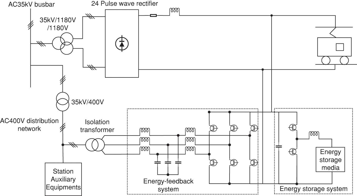
Figure 1: Construction of hybrid regenerative braking energy recovery system
Before connecting the regenerative braking energy recovery system, when a metro train is in traction operation,
After connecting the regenerative braking energy recovery system, the energy-storage system discharges to provide a part of the traction energy required by the train during traction operation and stores a part of the regenerative energy when the train brakes regeneratively. The energy-feedback system returns a part of braking energy to the AC 400 V grid. The energy relationship after connecting the hybrid system is as shown in Eqs. (3) and (4).
In Eqs. (1) to (4),
It is assumed that power flowing from the power supply network to the metro locomotive or other equipment is positive, while the power delivered by the train or other equipment to the power supply network is negative. In Eq. (5),
From Eqs. (3) and (4), it can be seen that in the traction mode of metro trains, the addition of an energy storage system results in the traction substation providing less energy. In the regenerative braking mode of metro trains, the energy-storage system and energy-feedback system absorb a portion of the regenerative braking energy. This reduces the energy sent back to the DC bus and the energy consumed by the brake resistor. Comprehensive analysis of the above indicates that the hybrid system is beneficial for achieving energy savings and effectively utilizing regenerative energy.
As a result of the foregoing analysis, it can be concluded that the power consumption of the traction substation and the AC 400 V grid can be reduced theoretically with the hybrid system. To achieve control over each system and utilize regenerative energy more effectively, a power management strategy that takes into account the fluctuation in power demand of the low-voltage loads will be proposed.
3 Dual-Mode Power Management Strategy
3.1 Division of Operating Mode and Sub-Reference Power Allocation
According to the fluctuation in power demand of low-voltage loads in metro stations during different seasons, the regenerative braking energy recovery system can operate in two modes: Mode 1, when the demand for low-voltage load power is low, and Mode 2, when the demand for low-voltage load power is high. The details of each mode are as follows:
(1) In spring and fall seasons, the outdoor temperature generally ranges between 18°C to 28°C when the metro is running. The air conditioning system in the metro station is opened for a short time during these seasons, resulting in low power requirements for the low-voltage load in the metro station. In this case, Mode 1 is used in the spring and fall seasons. In Mode 1, regenerative energy is prioritized to be stored by the energy-storage system to reduce the train’s power drawn from the power grid. Any excess energy is then recovered by the energy-feedback system when the energy-storage system is saturated.
(2) In summer, the outdoor temperature is higher than 26°C during metro operation, and in winter it is lower than 16°C. Therefore, the central air conditioning in metro stations will be operational for extended periods. During the summer, the number of passengers using the metro increases slightly as people tend to go out more. Consequently, the power consumed by the elevator system in metro stations will rise. Therefore, Mode 2 is adopted in summer and winter seasons. In Mode 2, the regenerative energy is prioritized to be sent back to the AC 400 V grid to supply the low-voltage load consumption in the station. Any excess energy is stored by the energy-storage system when the energy-feedback system reaches its limit.
In each mode, the energy-feedback system only operates when the train brakes regeneratively. The energy-storage system does not operate when the metro train is in a no-load condition or when the SOC exceeds the normal range. When the metro train is in the traction state and the SOC is normal, the energy-storage system can discharge. When the train is regeneratively braking and the SOC is normal, the energy-storage system can charge.
After the aforementioned process, if there is still an excess of regenerative energy, the DC busbar voltage will rise and reach the threshold for activating the braking resistor. This way, the train consumes the surplus energy on board instead of injecting it into the catenary.
With the above analysis, the dual-mode power management strategy of the regenerative braking energy recovery system can be formulated, as shown in Figs. 2a and 2b. Fig. 2a illustrates the power management strategy for Mode 1, while Fig. 2b depicts the power management strategy for Mode 2.
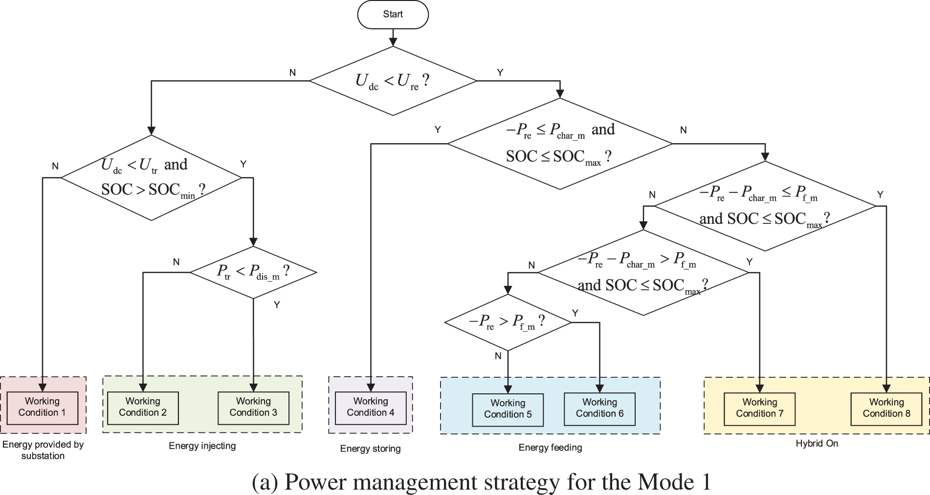
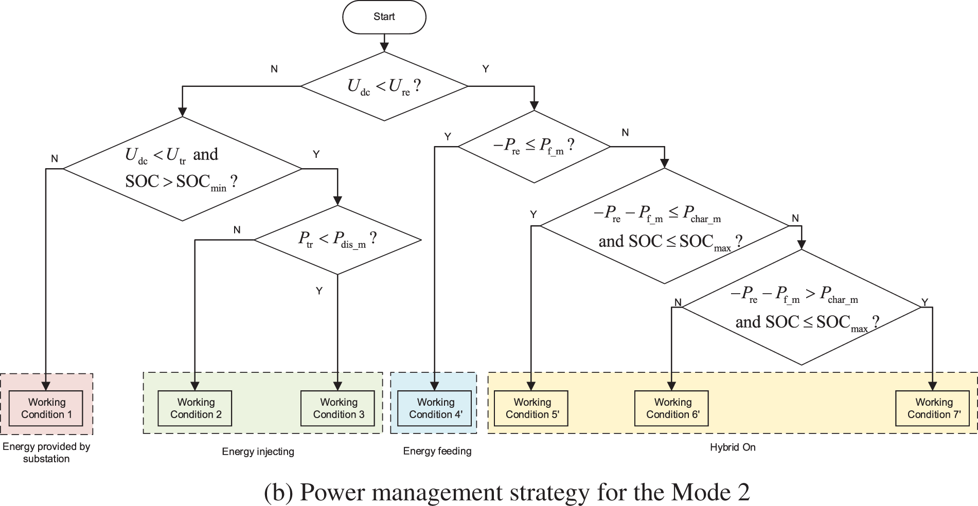
Figure 2: Dual-mode power management strategy
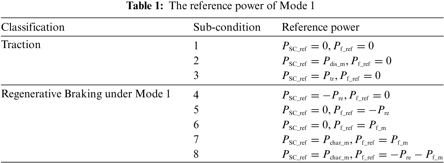
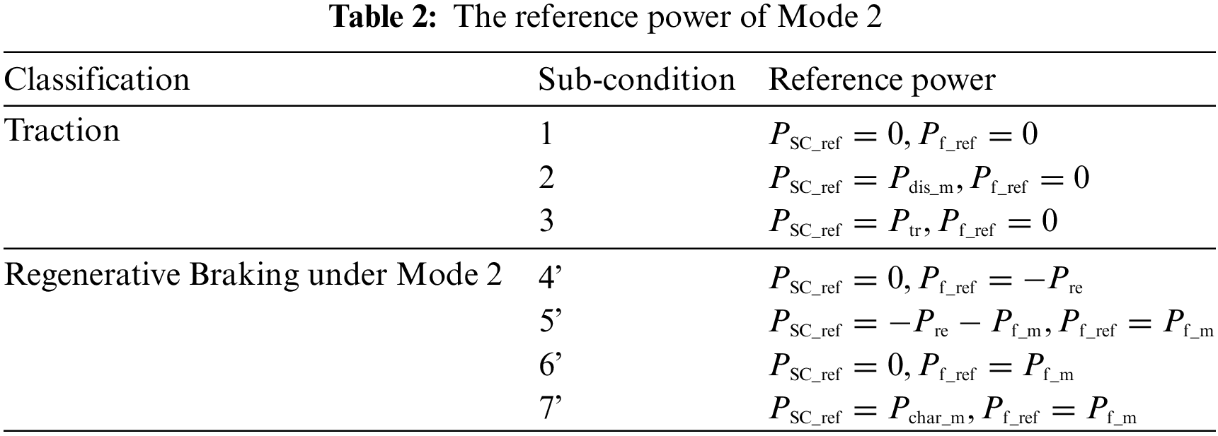
In the dual-mode strategy, Mode 1 is divided into 8 working conditions, while Mode 2 is divided into 7 working conditions. The reference power for each working condition can be obtained.
3.2 System Working Condition Classification and Reference Power Analysis
Combined with the running state of the metro train, the working conditions of Mode 1 and Mode 2 are classified as follows:
(1) Working conditions 1 to 3 of Mode 1 and Mode 2 are referred to as traction conditions.
(2) Working conditions 4 to 8 of Mode 1 are referred to as regenerative braking conditions within Mode 1.
(3) Working conditions from 4’ to 7’ of Mode 2 are referred to as regenerative braking conditions within Mode 2.
Each classification will be analyzed as follows:
(1) Traction: The energy-feedback system is inactive, and the energy-storage system discharges based on the SOC: if the SOC is normal, the energy-storage system discharges; if the SOC is abnormal, the metro train will draw power directly from the DC busbar.
(2) Regenerative Braking under Mode 1: If SOC is normal, the storage system will charge to
(3) Regenerative Braking under Mode 2: The energy will be sent to the AC 400 V grid preferentially until the feedback system reaches the maximum power. If the SOC is normal, the excess regenerative energy is stored by the storage system. If SOC is abnormal, the residual energy is consumed by the braking resistor.
With the dual-mode strategy,
By obtaining the reference power of each system, the control method can be formulated.
4.1 Control Method for Energy-Storage Systems
The control method of the energy-storage system involves a voltage and current double closed-loop control method, as illustrated in Fig. 3. The difference obtained by subtracting
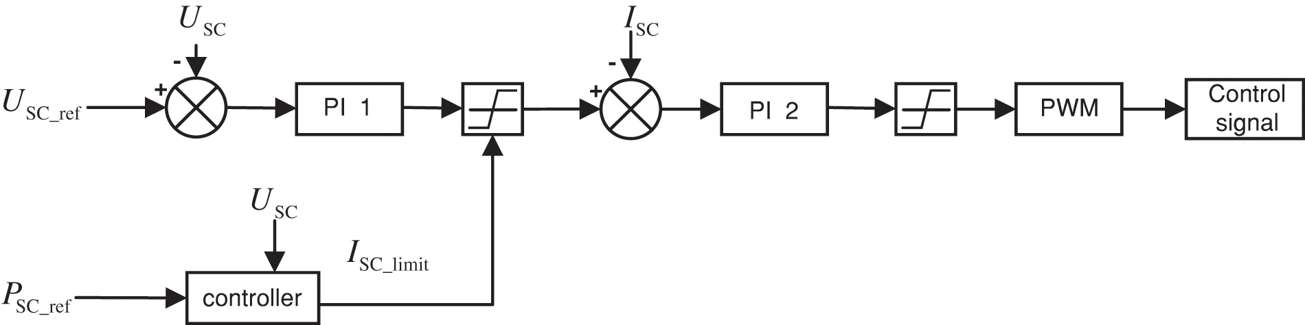
Figure 3: Energy-storage system control block diagram
When charging,
4.2 Control Method for Energy-Fed Systems
The energy-fed system control method adopts the space vector pulse width modulation (SVPWM) control technique. Fig. 4 shows the control block diagram of the energy-feedback system. The difference between
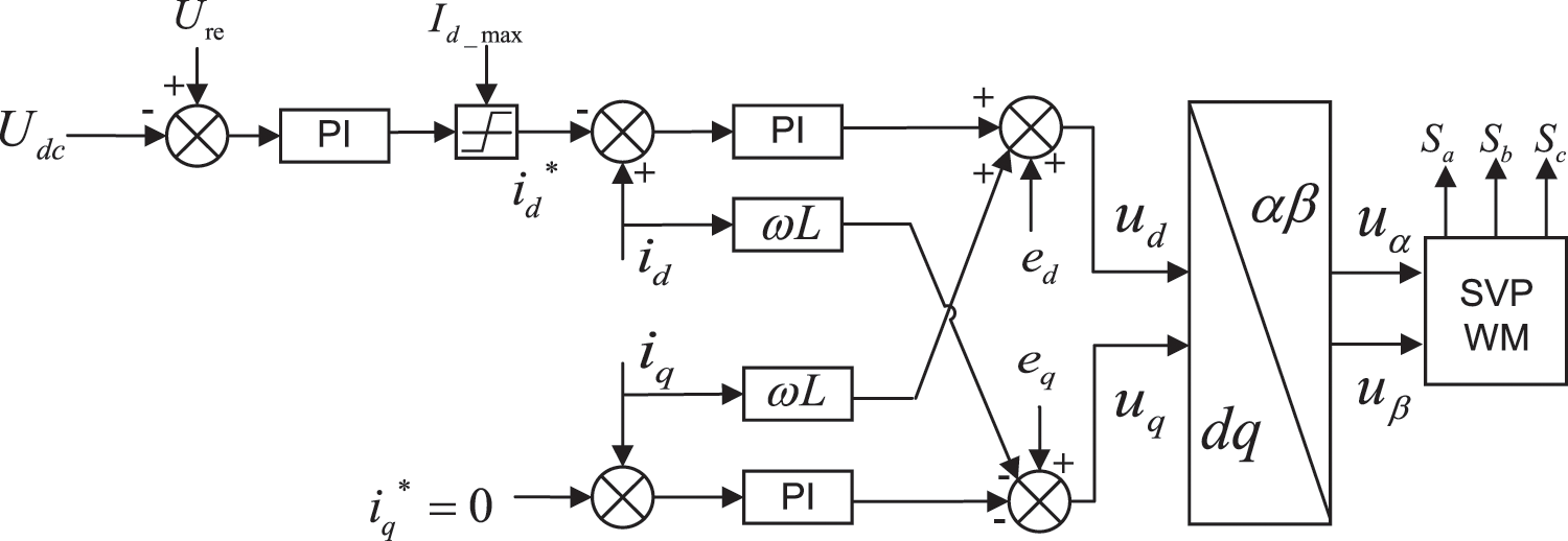
Figure 4: Energy-feedback system control block diagram
5 Simulation Verification and Analysis
5.1 Simulation of Working Conditions
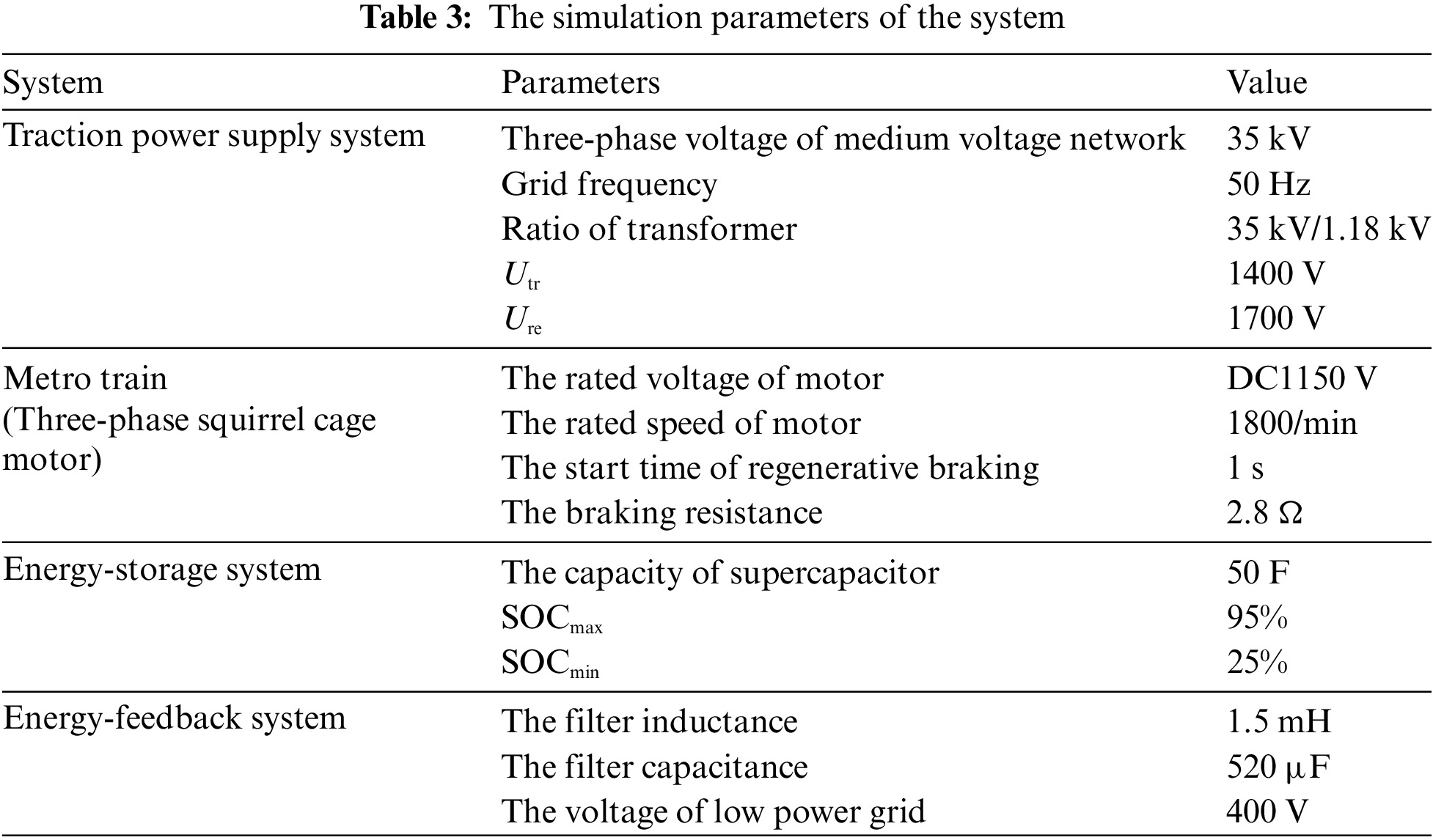
To verify the dual-mode power management strategy, a simulation model is constructed in the Matlab/Simulink platform, as shown in Fig. 1. The parameters of the simulation are as shown in Table 3.
In this simulation, the regenerative energy generated by the metro train is constant. The experimental conditions are altered by changing parameters
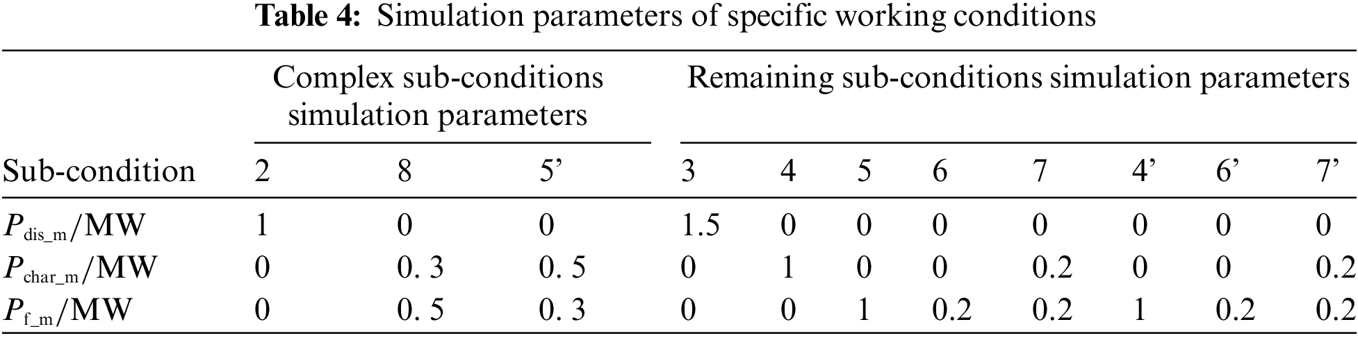
5.1.1 Sub-Condition 2 in Traction Condition
The simulation results of sub-condition 2 in the traction condition are shown in Figs. 5a and 5b. When the metro train starts, the DC busbar voltage drops to 1100 V without the energy-storage system in Fig. 5a, and the required traction power is about 2 MW in Fig. 5b. After accessing the system, the busbar voltage remains at 1400 V, and the required traction power of the train is reduced to about 1 MW.
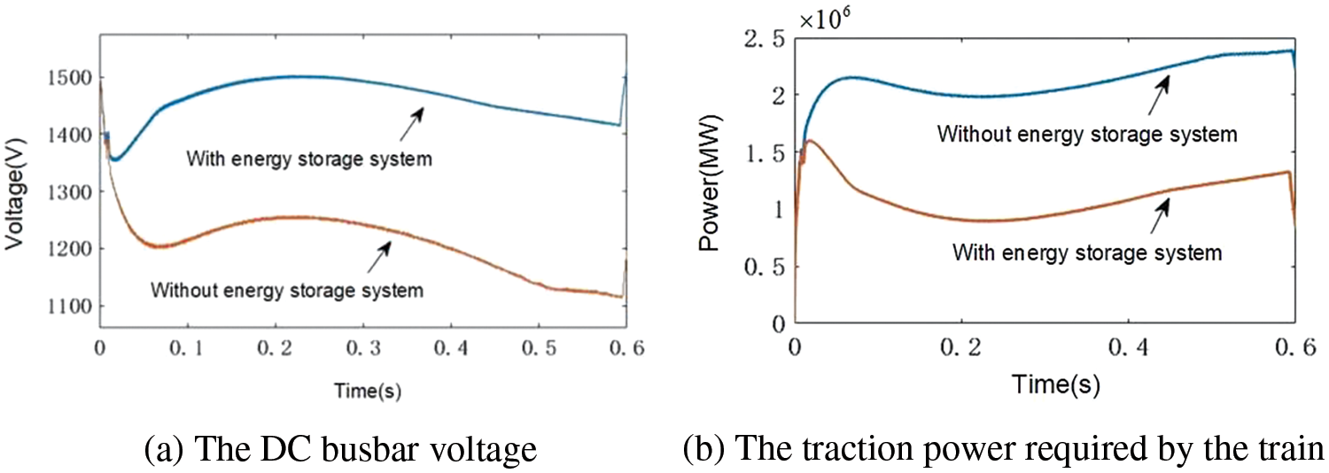
Figure 5: Simulation results of sub-condition 2 in Traction condition
5.1.2 Sub-Condition 8 in Regenerative Braking Condition under Mode 1
From Fig. 6a, the train brakes regeneratively at 1 s and the DC busbar voltage rises to 1800 V in Fig. 6a. Then the system recycles the regenerative braking power (about 0.5 MW) in Fig. 6b and the voltage decline to 1700 V. In Fig. 6c, the energy-storage system reaches its maximum charging power (0. 3 MW) and the remaining braking power (0.2 MW) is fed back by energy-feedback system.
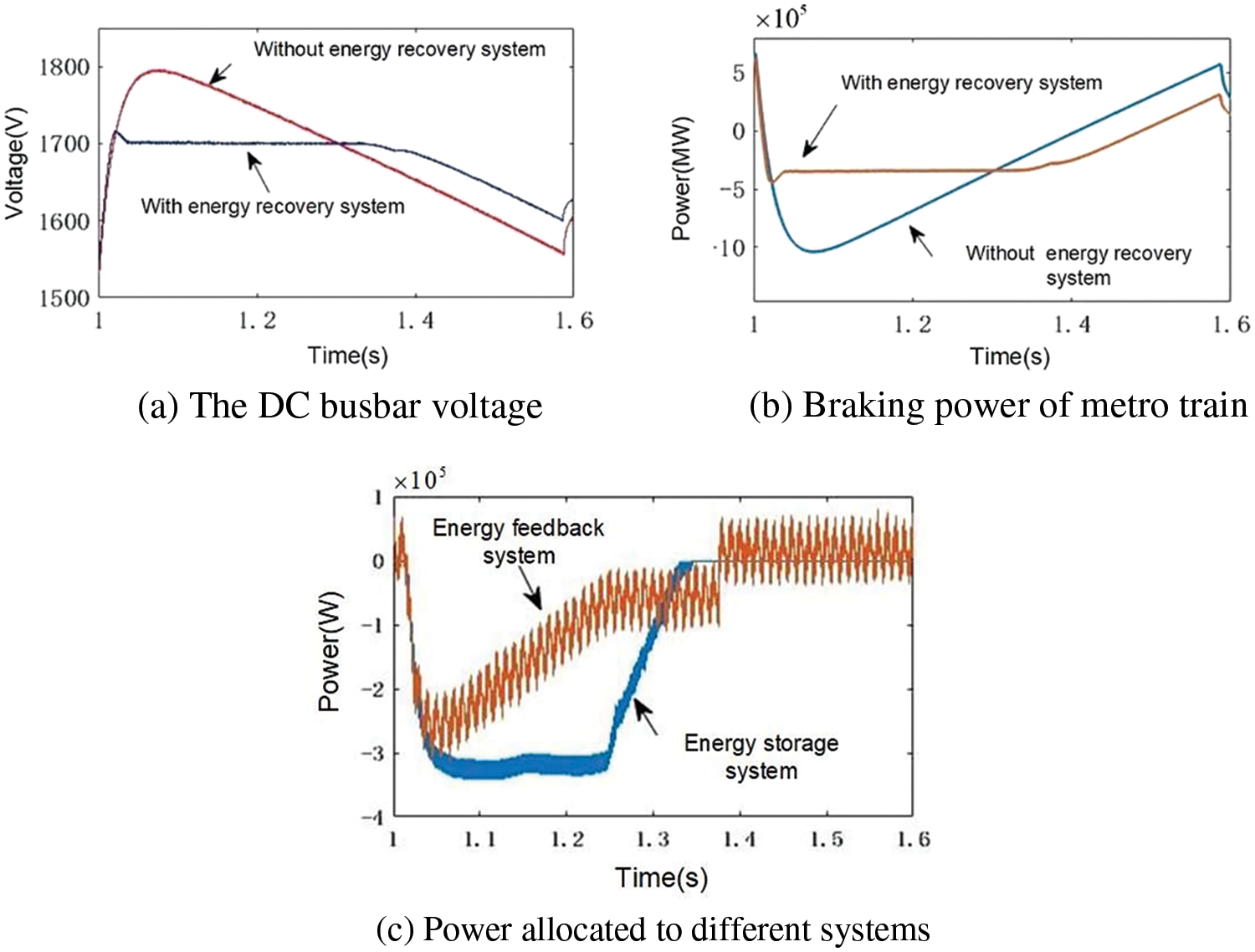
Figure 6: Simulation results of sub-condition 8 of low peak braking condition
5.1.3 Sub-Condition 5’ in Regenerative Braking Condition under Mode 2
In Figs. 7a–7c, the bus voltage rises to 1800 V at 1 s, and the energy-feedback system recycles braking power preferentially. After reaching
Figure 7: Simulation results of sub-condition 5’ in regenerative braking condition under Mode 2
5.1.4 Verification of Remaining Sub-Condition Simulation
The simulation results of the remaining sub-conditions are shown in Figs. 8a–8h. From Figs. 8a–8h, it can be seen that the power allocation is feasible, indicating that the dual-mode strategy is effective.
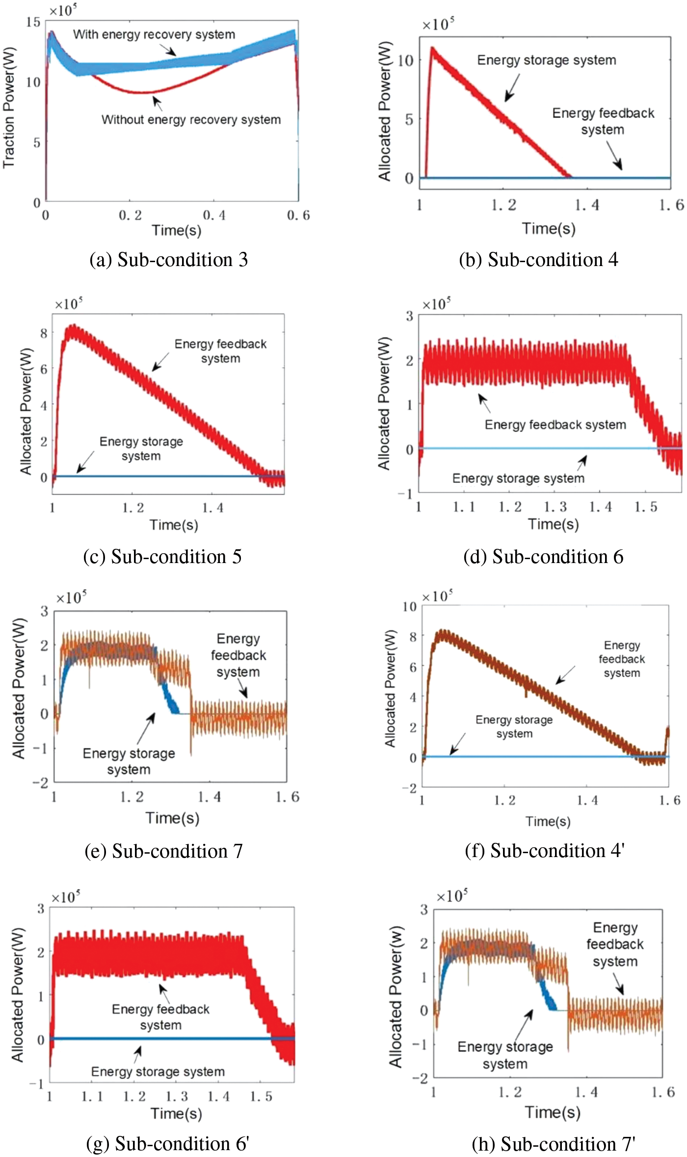
Figure 8: Simulation results of power allocation for remaining sub-conditions
5.2 Comparison of Different Regenerative Braking Energy Recovery Systems
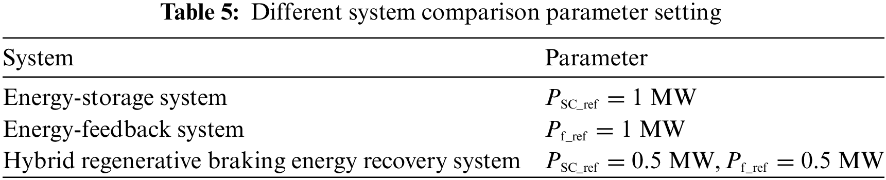
Under the same simulation conditions and control methods, the hybrid system is compared with the systems using a single technology (the system using energy storage technology and the system using energy feedback technology). The impact on the DC busbar voltage and energy recovery is verified. Table 5 shows the comparison of system parameter settings.
Figs. 9a and 9b show the result. In Fig. 9a, the peak voltage of systems using a single technology is 1780 V, and reducing the voltage to 1700 V takes more time. In contrast, the hybrid system can quickly stabilize the voltage at 1700 V.
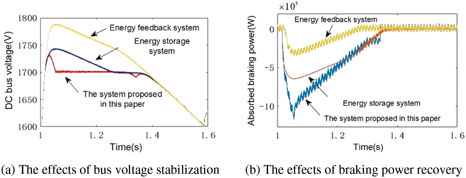
Figure 9: Comparison of different regenerative braking energy recovery systems
As can be seen from Fig. 9a and 9b, the single energy-feedback system recovers only 0.2 MW of braking power, while the single energy-storage system recovers about 0.6 MW. With the proposed energy strategy, the hybrid system can recover approximately 1 MW of braking power.
In summary, when compared to systems using a single technology, the hybrid system with a dual-mode strategy has a more significant impact on busbar voltage and energy recovery.
5.3 System Regenerative Braking Simulation without Dual-Mode Power Management Strategy
To assess the impact of the dual-mode power management strategy on the hybrid system, the simulation of regenerative braking without the dual-mode strategy is conducted. The result is as shown in Figs. 10a and 10b. The effect of ensuring the busbar voltage safety is evident in Fig. 10a. However, Fig. 10b illustrates that almost all the energy is stored by the energy-storage system, and the feedback system is not functioning because the bus voltage has not exceeded 1700 V.
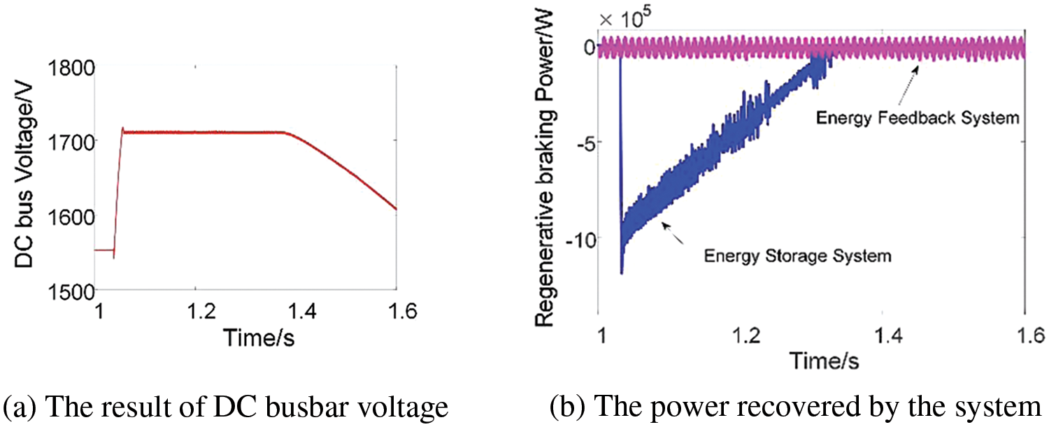
Figure 10: The simulation result without dual-mode power management strategy
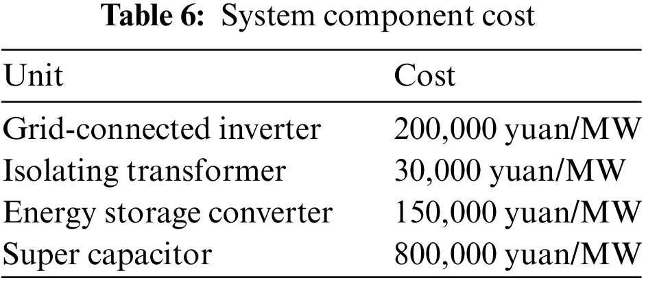
Although the effect of stabilizing bus voltage is positive and almost all the energy is stored without the dual-mode strategy, the cost is higher according to Table 6 (the data are derived from reference 17): if the system does not use the dual-mode strategy, the energy-storage system will be configured with a large power capacity and cost about 1,400,000 yuan (approximately $195,000). By contrast, the system that utilizes the dual-mode strategy could ensure the safety of the DC busbar voltage and absorb all the energy at a lower cost. For instance, if the hybrid system comprises a 0.5 MW energy-storage system and a 0.5 MW energy-feedback system, the total cost would be only 590,000 yuan (approximately $82,350). Therefore, the dual-mode power management strategy has certain advantages in terms of technology and economy.
To efficiently recycle the regenerative braking energy of a metro train, a hybrid regenerative braking energy recovery system with a dual-mode power management strategy is proposed, taking into account the power demand of low-voltage loads in metro stations. The theoretical analysis and simulation experiments above lead to the following conclusions:
(1) The hybrid system and its dual-mode strategy can effectively recycle regenerative energy, which has a positive impact on the DC busbar voltage.
(2) Under the same reference power and control methods, the hybrid system with the power management strategy has a better effect on voltage stabilization and energy recovery compared to systems using a single technology.
(3) The dual-mode power management strategy can accurately allocate power to meet the power requirements of each system. Systems employing the dual-mode strategy can efficiently recycle regenerative energy and cut down on costs.
(4) This paper mainly studies the ideal hybrid RBE system with a dual-mode energy management strategy to recover the regenerative braking power of trains and does not consider influencing factors such as line impedance. The research conclusions are limited to most metro lines in China, and the optimization of capacity configuration under the hybrid RBE system is not discussed. The limitations of the paper suggest a potential direction for future research.
Acknowledgement: None.
Funding Statement: This research was funded by Project supported by the Natural Science Foundation of Gansu Province, China (Grant No. 22JR5RA318). The project manager is X. Chen, and the sponsors’ website is Science and Technology Deparment of Gansu Province.
Author Contributions: The authors confirm contribution to the paper as follows: study conception and design: Feng Zhao, Xiaotong Zhu, Xiaoqiang Chen, Ying Wang; data collection: Xiaotong Zhu; analysis and interpretation of results: Xiaotong Zhu; draft manuscript preparation: Xiaotong Zhu. All authors reviewed the results and approved the final version of the manuscript.
Availability of Data and Materials: Data available within the article.
Conflicts of Interest: The authors declare that they have no conflicts of interest to report regarding the present study.
References
1. C. Liu et al., “Power management and capacity optimization of photovoltaic, energy-storage system, flexible building power system considering combined benefit,” Energy Eng., vol. 120, no. 2, pp. 541–559, Nov. 2022. doi: 10.32604/ee.2022.022610. [Google Scholar] [CrossRef]
2. J. Shi, L. Yang, J. Yang, and Z. Gao, “Service-oriented train timetabling with collaborative passenger flow control on an oversaturated metro line: An integer linear optimization approach,” Transport. Res. Part B: Method., vol. 110, pp. 26–59, Feb. 2018. doi: 10.1016/j.trb.2018.02.003. [Google Scholar] [CrossRef]
3. X. Li and H. Luo, “An energy-efficient scheduling and speed control approach for metro rail operations,” Trans. Res. Part B: Method., vol. 64, pp. 73–89, Apr. 2014. doi: 10.1016/j.trb.2014.03.006. [Google Scholar] [CrossRef]
4. D. Liu, S. Zhu, Y. Bi, K. Liu, and Y. Xu, “Research on the utilization of metro regenerative braking energy based on an improved differential evolution algorithm,” J. Adv. Transport., vol. 2020, pp. 7085809, 2020. doi: 10.1155/2020/7085809. [Google Scholar] [CrossRef]
5. J. Li et al., “Energy-saving metro train timetable optimization method based on a dynamic passenger flow distribution,” J. Adv. Transport., vol. 2020, pp. 9776845, 2022. doi: 10.1155/2022/9776845. [Google Scholar] [CrossRef]
6. F. Ciccarelli, D. Iannuzzi, and P. Tricoli, “Control of metro-trains equipped with onboard supercapacitors for energy saving and reduction of power peak demand,” Transport. Res. Part C: Emerg.Technol., vol. 24, pp. 36–49, Mar. 2012. doi: 10.1016/j.trc.2012.02.001. [Google Scholar] [CrossRef]
7. G. Du et al., “Maximum safety regenerative power tracking for DC traction power systems,” Energies, vol. 10, no. 2, pp. 244, Feb. 2017. doi: 10.3390/en10020244. [Google Scholar] [CrossRef]
8. M. Khodaparastan, A. A. Mohamed, and W. Brandauer, “Recuperation of regenerative braking energy in electric rail transit systems,” IEEE Trans. Intell. Transp. Syst., vol. 20, no. 8, pp. 2831–2847, Aug. 2019. doi: 10.1109/TITS.2018.2886809. [Google Scholar] [CrossRef]
9. X. Yang, X. Li, B. Ning, and T. Tang, “A survey on energy-efficient train operation for urban rail transit,” IEEE Trans. Intell. Transp. Syst., vol. 17, no. 1, pp. 2–13, Jan. 2016. doi: 10.1109/TITS.2015.2447507. [Google Scholar] [CrossRef]
10. D. He, Y. Yang, J. Zhou, and Y. Chen, “Optimal control of metro energy conservation based on regenerative braking: A complex model study of trajectory and overlap time,” IEEE Access, vol. 7, pp. 68342–68358, 2019. doi: 10.1109/ACCESS.2019.2918938. [Google Scholar] [CrossRef]
11. B. Tan, H. Jin, S. Liu, and S. Chen, “Optimization on train operation organization of full-length and short-turn routing mode considering the occupation of turn-back route,” (in ChineseJ. Railway Sci. Eng., vol. 19, no. 8, pp. 2161–2168, 2022. doi: 10.19713/j.cnki.43-1423/u.t20211009. [Google Scholar] [CrossRef]
12. L. Huo et al., “A novel DC traction power supply system based on the modular multilevel converter suitable for energy feeding and de-icing,” CSEE J. Power Energy Syst., vol. 10, no. 2, pp. 649–659, Mar. 2024. doi: 10.17775/CSEEJPES.2020.02260. [Google Scholar] [CrossRef]
13. H. Liu et al., “Timetable optimization for regenerative energy utilization in metro systems,” IEEE Trans. Intell. Transp. Syst., vol. 20, no. 9, pp. 3247–3257, Sep. 2019. doi: 10.1109/TITS.2018.2873145. [Google Scholar] [CrossRef]
14. S. Lin et al., “Research on the regeneration braking energy feedback system of urban rail transit,” IEEE Trans. Vehicular Technol., vol. 68, no. 8, pp. 7329–7339, Aug. 2019. doi: 10.1109/TVT.2019.2921161. [Google Scholar] [CrossRef]
15. F. Zhu, Z. Yang, F. Lin, and Y. Xin, “Decentralized cooperative control of multiple energy storage systems in urban railway based on multiagent deep reinforcement learning,” IEEE Trans. Power Electron., vol. 35, no. 9, pp. 9368–9379, Sep. 2020. doi: 10.1109/TPEL.2020.2971637. [Google Scholar] [CrossRef]
16. Y. Liu, Z. Yang, F. Lin, X. Fang, and H. Sun, “Study on adaptive power management and optimal capacity configuration of urban rail ground hybrid energy-storage system,” (in ChineseTransact. China Electrotech. Soc., vol. 36, no. 23, pp. 4874–4884, 2021. doi: 10.19595/j.cnki.1000-6753.tces.210853. [Google Scholar] [CrossRef]
17. H. Hu et al., “Research on regenerative braking energy storage and utilization technology for high-speed railways,” (in ChineseProc. CSEE, vol. 4, no. 1, pp. 246–256, 2020. doi: 10.13334/j.0258-8013.pcsee.190650. [Google Scholar] [CrossRef]
18. W. Jefimowski, A. Nikitenko, Z. Drazek, and M. Wieczorek, “Stationary supercapacitor energy storage operation algorithm based on neural network learning,” Bullet. Acad. Sci.-Tech. Sci., vol. 68, no. 4, pp. 733–738, 2020. doi: 10.24425/bpasts.2020.134176. [Google Scholar] [CrossRef]
19. X. P. Chen, Y. D. Wang, and Q. M. Wu, “A bio-fuel power generation system with hybrid energy storage under a dynamic programming operation strategy,” IEEE Access, vol. 7, pp. 64966–64977, 2019. doi: 10.1109/ACCESS.2019.2911454. [Google Scholar] [CrossRef]
20. D. Bi, Q. Zhang, and B. Ge, “Research on power grid energy storage of the regenerative braking energy,” (in ChineseUrban Mass Transit, vol. 17, no. 11, pp. 36–40+45, 2014. doi: 10.16037/j.1007-869x.2014.11.010. [Google Scholar] [CrossRef]
21. Z. Li et al., “Hybrid regenerative braking energy utilization system and its control method in urban rail transit,” (in ChineseElect. Power Automat. Equip., vol. 43, no. 11, pp. 203–210, 2022. doi: 10.16081/j.epae.202211022. [Google Scholar] [CrossRef]
22. D. Wang and G. Lu, “Demand coefficient of low-voltage load for urban rail transit station,” (in ChineseUrban Rapid Rail Transit., vol. 30, no. 5, pp. 93–98, 2017. doi: 10.3969/j.issn.1672-6073.2017.05.017. [Google Scholar] [CrossRef]
Cite This Article
 Copyright © 2024 The Author(s). Published by Tech Science Press.
This work is licensed under a Creative Commons Attribution 4.0 International License , which permits unrestricted use, distribution, and reproduction in any medium, provided the original work is properly cited.
 Downloads
 Citation Tools