 Open Access
ARTICLE
Adaptive Predefined-Time Backstepping Control for Grid Connected Photovoltaic Inverter
1 Key Laboratory of Smart Grid of Ministry of Education, Tianjin University, Tianjin, 300072, China
2 State Grid Hubei Electric Power Research Institute, Wuhan, 430077, China
3 State Grid Hubei Electric Power Co., Ltd., Wuhan, 430077, China
* Corresponding Author: Dan Liu. Email:
Energy Engineering 2024, 121(8), 2065-2083. https://doi.org/10.32604/ee.2024.050342
Received 03 February 2024; Accepted 10 April 2024; Issue published 19 July 2024
Abstract
The system performance of grid-connected photovoltaic (PV) has a serious impact on the grid stability. To improve the control performance and shorten the convergence time, a predefined-time controller based on backstepping technology and dynamic surface control is formulated for the inverter in the grid-connected photovoltaic. The time-varying tuning functions are introduced into state-tracking errors to realize the predefined-time control effect. To address the “computational explosion problem” in the design process of backstepping control, dynamic surface control is adopted to avoid the analytical calculations of virtual control. The disturbances of the PV system are estimated and compensated by adaptive laws. The control parameters are chosen and the global stability of the closed-loop is ensured by Lyapunov conditions. Simulation results confirm the effectiveness of the proposed controller and ensure the predefined time control in the photovoltaic inverter.Keywords
As economic development accelerates, the demand for energy transformation continues to rise due to the increasing consumptions of fossil fuels [1]. In comparison to traditional fossil fuels, renewable energy offers the benefits of widespread distribution, diverse sources and reduced environmental pollution [2]. Consequently, the grid-connection rate for renewable energy is on the rise within the energy sector [3]. Furthermore, the rapid development of power electronics technology has significantly enhanced access to the deployment of renewable energy [4]. Recently, as a sustainable and clean energy source, photovoltaics has attracted more attention and investments in many countries [5–7]. Grid-connected inverters receive important research value in photovoltaic powers and renewable energy fields [8–10].
Large-scale grid-connection of photovoltaic strives for new requirements in system stability and convergence [11]. Currently, kinds of control methods have been explored in engineering practices [12–14]. In the field of microgrid control, finite-time control algorithms have been developed to track reference commands within a finite time [15–17]. In the islanded systems, the smooth power control for PV inverters has been designed using an adaptive finite-time sliding mode technique, ensuring finite-time stability and convergence of the tracking errors [18]. Reference [19] proposes a continuous sliding mode control within finite time for grid-connected photovoltaic arrays, addressing modeling uncertainties arising from variations in converter parameters, system frequency and exogenous factors. To mitigate power chattering in the photovoltaic inverter of the master-slave island microgrid system, the adaptive sliding mode backstepping control has been studied, which can ensure the finite-time stability, favorable robustness performance and shortened convergence time of system states [20]. Finite-time control can ensure the finite time tracking of the system’s solution, while the upper bound of the convergence time is influenced by the system’s initial state.
Subsequently, a fixed-time control algorithm is investigated, which can ensure the convergence of tracking errors in a fixed time range. The convergence speed of fixed-time control is further enhanced and the convergence time is independent of the system’s initial conditions [21]. However, the upper bound of the convergence time cannot be explicitly determined by the control parameters [21–23]. Regarding the issue of the system level frequency deviation by the power output randomness and PV generation, the control of bus overvoltage and power output is accomplished, ensuring the fixed time response in the battery energy storage systems [24]. Considering the intermittent power from renewable energy sources and frequent load fluctuations affecting the microgrid cluster, a two-layer two-level control is developed to enhance the dynamic performance of the microgrids within a fixed time [25]. Recently, deep researches on predefined time control algorithms have appeared [26,27].
Predefined time control is proposed while the upper limit of the stable time function can be determined by selecting system parameters appropriately. In [28], the secondary controller with a predefined time is formulated for the direct current (DC) microgrid, facilitating voltage regulation and current sharing among different distributed generators within a specified time. The predefined time control algorithm can provide a preset convergence time, which can be determined explicitly by the controller gains in advance [29]. The harmonics in photovoltaics have serious effects on the grid, therefore the rapid convergence of the voltage/current in photovoltaic inverters is important. Table 1 shows the comparison results of different control methods. Compared with finite time control and fixed-time control, the maximum limit of the convergence time in a predefined time control can make the theoretical value of the convergence time a simple and adjustable parameter.
Based on the aforementioned research, a predefined-time backstepping control is studied for the grid-connected photovoltaic inverters. The main contributions of the paper lie in:
1. A predefined time backstepping control based on initial states is proposed for the three-phase grid-connected photovoltaic inverter. The proposed control scheme ensures that the output states can convergent into a small region around the origins in a predefined time.
2. Compared to semi-global stability in [12–14], the control algorithm adopts the Lyapunov condition to ensure global closed-loop stability, realizes DC voltage tracking and unit power factor grid-connection within the predefined time.
3. In comparison with the finite-time control and fixed-time control, the proposed predefined-time control can effectively improve the convergence speed of the PV system and achieve an accurate estimation of the upper limit of convergence time.
The remainder of the paper is outlined as follows. Section 2 describes the topology architecture of the PV system, the mathematical model of the inverter and time-varying functions. Section 3 devises a predefined-time control based on backstepping and adaptive control. In Section 4, the global closed-loop stability analysis and the choices of the controller gains are present. Section 5 carries on the simulation experiments and analyses. Section 6 summarizes the paper.
The control objective of grid-connected inverters is to maintain the stability of the DC side voltage and achieve unit power factor grid-connection. Inverters are susceptible to device aging, thermal effects, grid voltage uncertainty and external disturbances. Therefore, the control of grid-connected inverter should meet grid-connection requirements and exhibit robustness, while providing the improved system stability and convergence speed. A three-phase voltage source inverter (VSI) is modeled in a single-stage non-isolated grid-connected topology and a predefined-time control is formulated.
As shown in Fig. 1, the topology structure diagram of a three-phase photovoltaic grid-connected inverter is stated, where
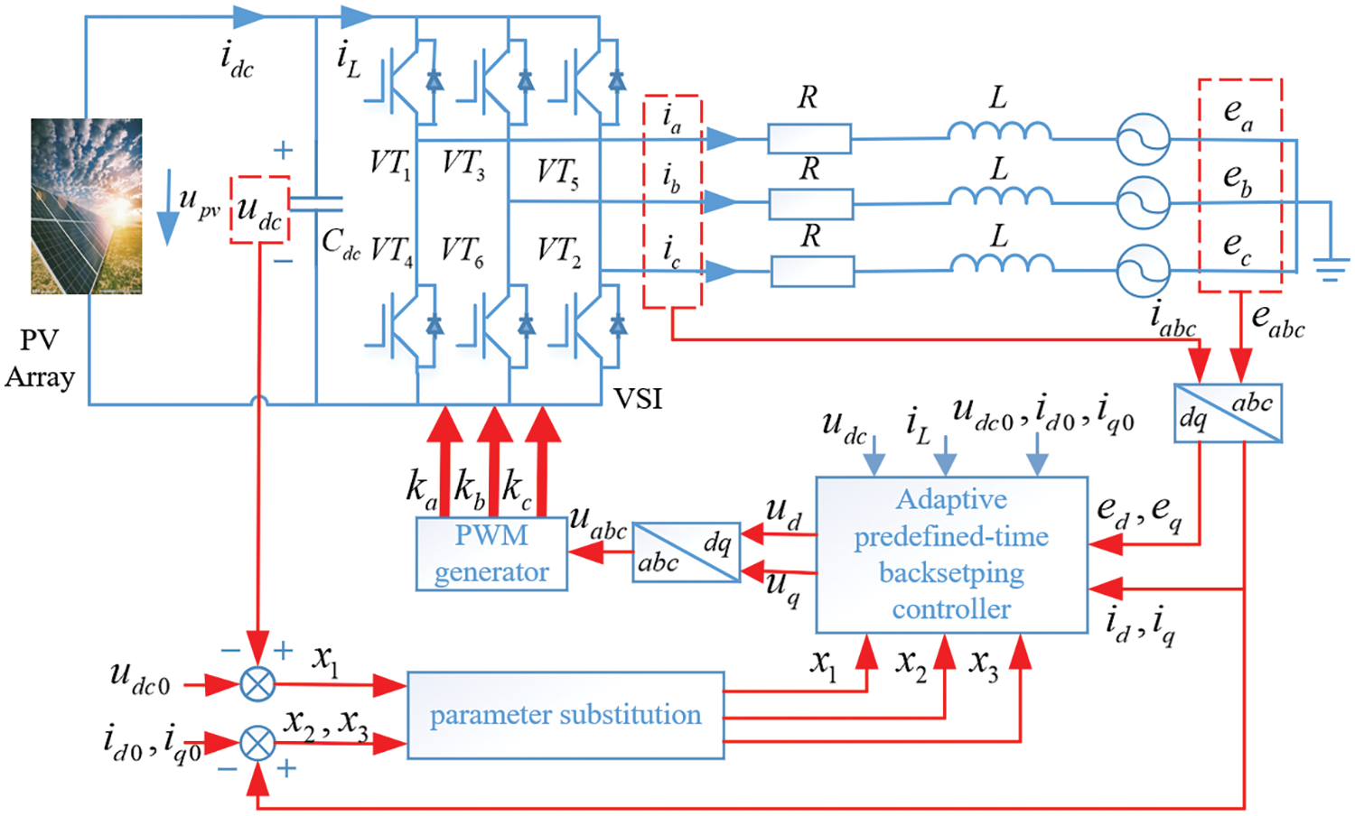
Figure 1: Topological structure diagram of three-phase PV grid-connected inverter
Eq. (1) provides the relationship of current and voltage in the three-phase grid-connected system, where
with
Basen on the Kirchhoff’s current law, the voltage
where
After ignoring the fluctuation of
By invoking Eqs. (3) and (5), we can obtain
Define the reference signal of voltage
where the system state variables are chosen as
For all headings, please capitalize the first character of each word except prepositions, and conjunctions.
The control object is to formulate the predefined time control laws
Lemma 1 [32]. For an n-order system
Lemma 2 [33]. For
The following assumptions hold for the VSI system (7).
Assumption 1 [34]. The unknown external disturbances
Assumption 2. The gain functions in inverter dynamics (7) are uniformly continuous satisfying
Assumption 3. Other functions in inverter dynamics (7) and their first time-derivatives are uniformly continuous.
Remark 1. Due to the randomness of photovoltaic power generation, the uncertainty of bus voltage, the aging problems and thermal effects in the inverter, disturbances terms should be considered. In practical systems, disturbances are usually subjected to various physical limitations, such as power supply stability, circuit design and the effects of filters. These factors result in the limited magnitude of disturbances within a certain range, making the disturbances bounded. Therefore, Assumption 1 holds. Assumptions 2 and 3 are reasonable as active power
For all headings, please capitalize the first character of each word except prepositions, and conjunctions.
The predefined time constant is introduced directly in the predefined-time control, allowing for the adjustment of different predefined times by choosing the value of the time constant in advance. The time-varying function
Condition 1. Time-varying function
Condition 2. Time-varying function
Condition 3.
Condition 4. The initial values
where
For the 1-order system of the Q-axis, the time-varying function
Condition 5.
Condition 6.
Condition 7.
Condition 8. The initial value
and
Remark 2. Time-varying functions are used to achieve the desired tracking performance with a stable time-upper limit. The controller design ensures that the output tracking errors of the system can track the desired trajectory. The upper limit of the system’s convergence time can be adjusted by determining the time constant
3 Adaptive Predefined-Time Backstepping Control
The adaptive control is formulated to estimate and compensate for the disturbances in inverter model (7). The time-varying function
Fig. 2 states the signal diagram of the closed-loop system. Adaptive control laws are introduced to estimate and compensate for the upper limit
where
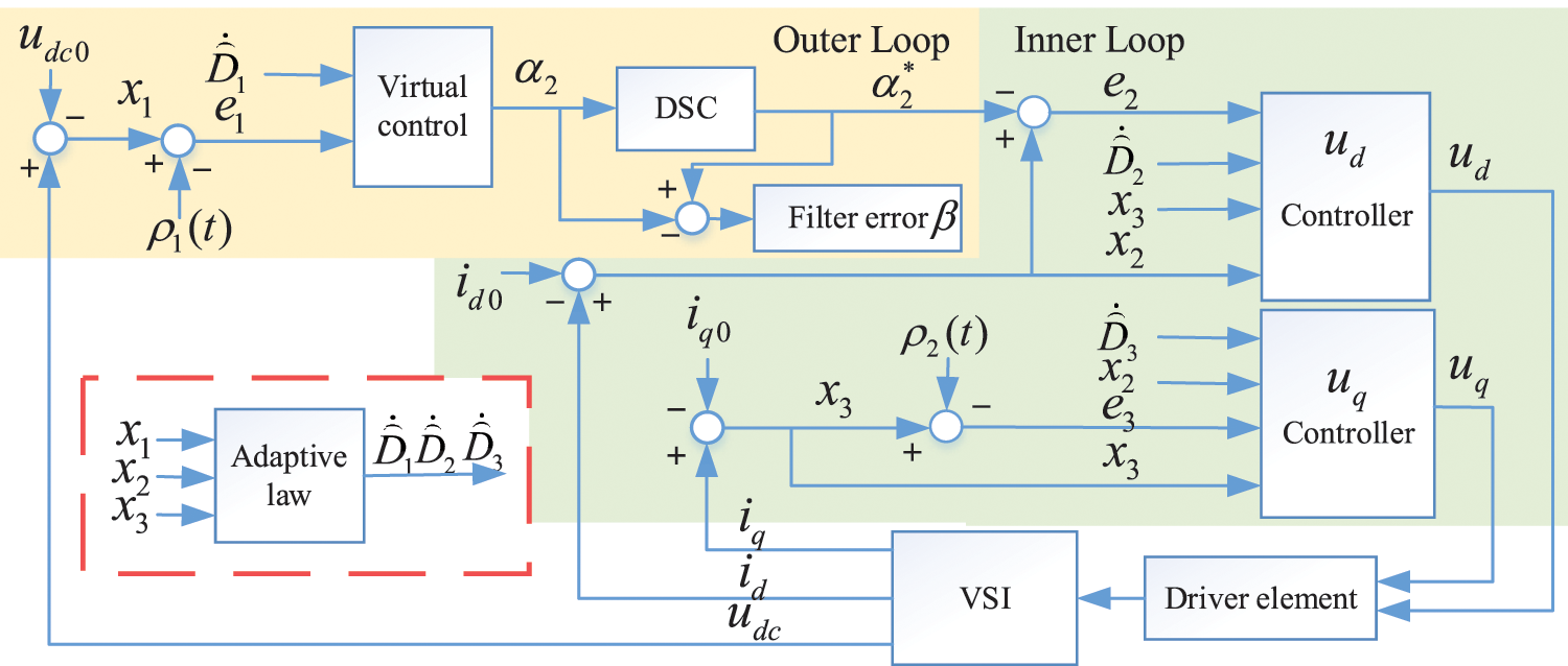
Figure 2: Signal diagram of the closed-loop system
The state tracking error is designed
where
The first-time derivative of
The virtual control law
where
Substituting the virtual controller (15) into Eq. (14) yields
Choose a Lyapunov function candidate
Along the trajectories (12), (15) and (16), the first-time derivative of
The following inequalities hold by Young’s inequality
To avoid the “computational explosion problem” in backstepping control, the dynamic surface control (DSC) is introduced. That is, the signal
where
Define the state tracking errors
The first-time derivative of
The control laws
where
Consider the following Lyapunov function
Substituting Eq. (25) into the differential dynamic of
with inequalities
The state tracking errors
where
The first-time derivative of
The control laws
where
Define a Lyapunov function candidate
The time derivative of
where the inequalities
Choosing the total Lyapunov function
From Eqs. (18), (27) and (33),
where
By the Lyapunov theory, the predefined time stability of the closed-loop system is achieved, which is summarized in Theorem 1.
Theorem 1. For the inverter (7) in the PV system, the control laws
Poof. Define a vector
The controller gains are selected as
From Eqs. (35)–(37), we can deduce that
Next, the discussion focuses on the boundedness of signals in the closed-loop system in the compact set
Invoking the definition
The first derivation of the virtual controller
Apparently
In addition, according to Eq. (36),
Remark 3. For
1. Based on the initial states (8) and (10), select the suitable time-varying functions (9) and (11) to fulfill the predefined time stability conditions.
2. Choose the appropriate parameters
3. Choose appropriate parameters
The simulation is carried on the photovoltaic system to demonstrate the effectiveness of the proposed control method. The physical parameters are as follows:
Case1. Simulations under different predefined times
The initial condition is set to
Fig. 3 shows the trajectories of state

Figure 3: State variables and tracking errors at
Figs. 4a and 5a show the trajectories of state variables

Figure 4: State variables and tracking errors at

Figure 5: State variables and tracking errors at
A comparison simulation of finite-time backstepping control and fixed-time backstepping control are performed. Fig. 6a shows the trajectories of state variables

Figure 6: State variables and tracking errors in traditional backstepping controller
Fig. 7 shows the estimation value of the virtual control at
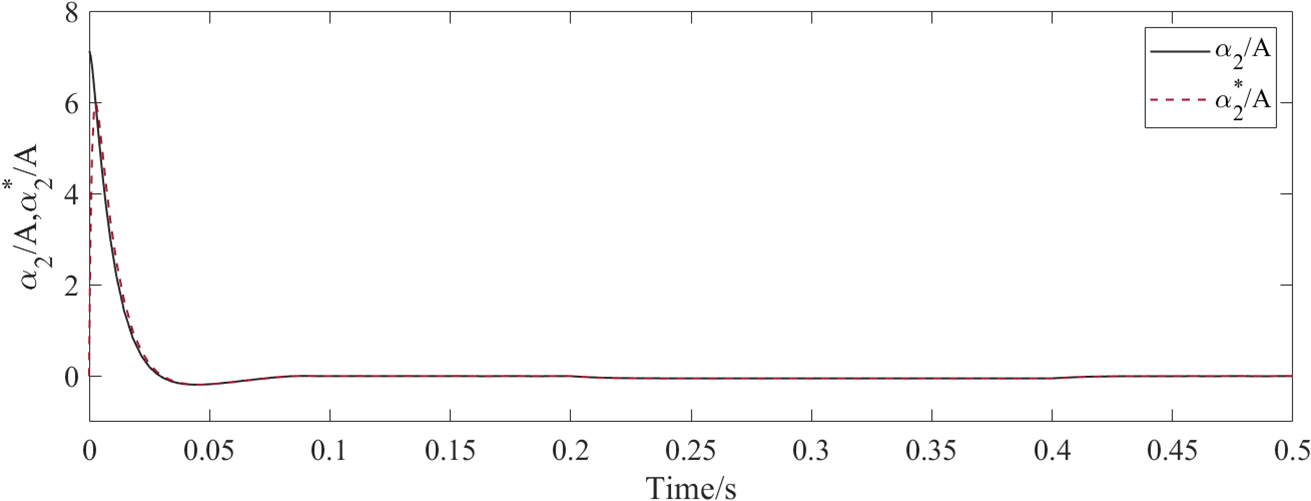
Figure 7: Estimation value of virtual controller at

Figure 8: Controllers under different predefined times
Case2. Simulation under different initial states
To address the tracking performance of the controller, different initial states
Fig. 9 displays the state responses
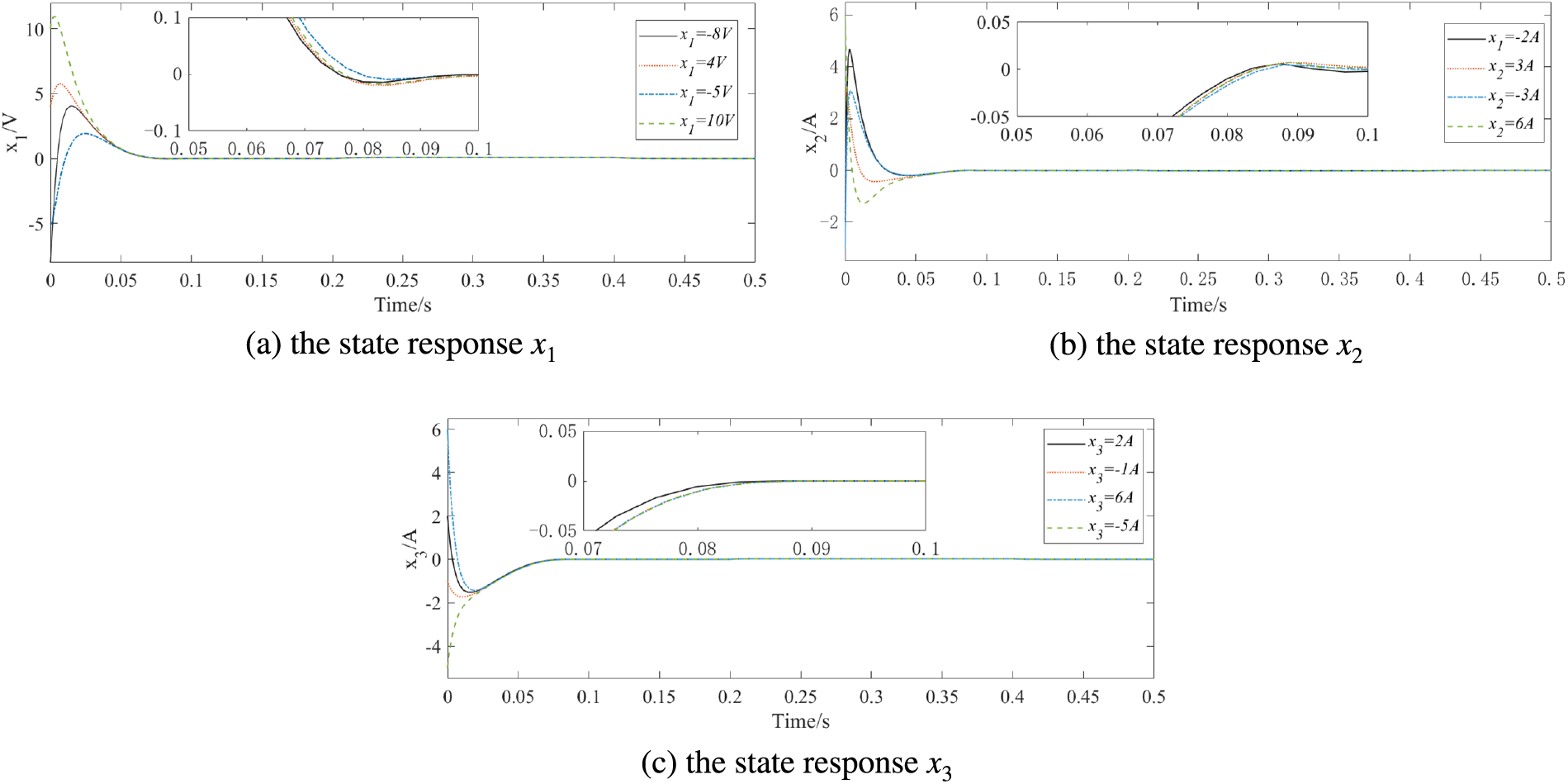
Figure 9: State response under different initial states at
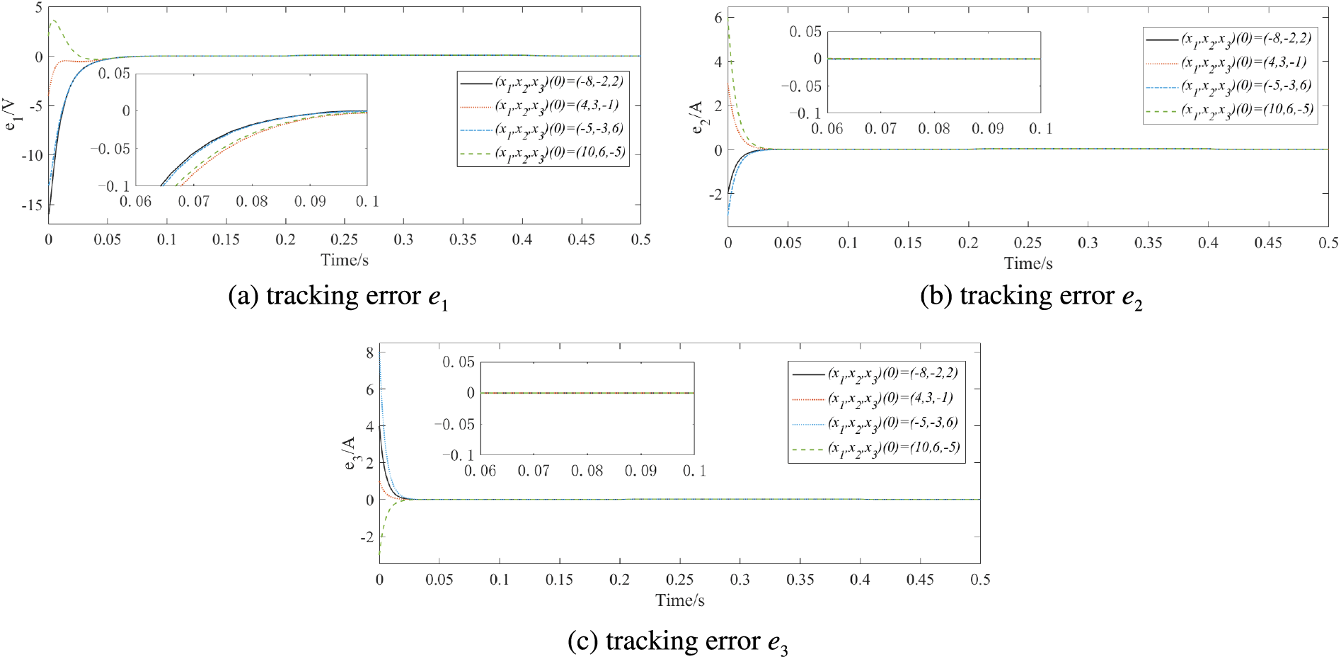
Figure 10: Tracking errors under different initial states at
Fig. 11 illustrates the curves of state variables in finite time backstepping control under different initial states. Apparently, the tracking process of state variables is slow and the trajectory changes are small under different initial states, achieving tracking about 0.35 s. Fig. 12 depicts the state responses variables in a fixed-time controller under different initial states. The convergence time of fixed time control has been improved and effective tracking can be achieved in different initial states, while the tracking goal is reached within 0.2 s. Compared with finite-time control and fixed-time control, predefined time control can approach the upper limit of convergence time more accurately, while provide the improved convergence speed and control performance effectively.
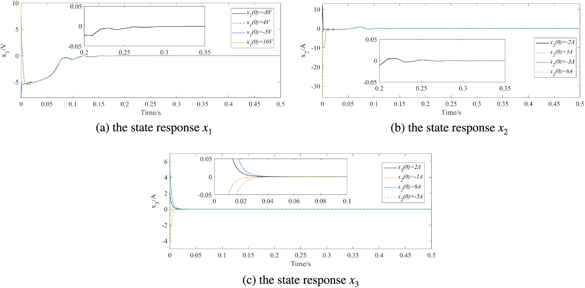
Figure 11: State responses under different initial states in finite-time backstepping controller
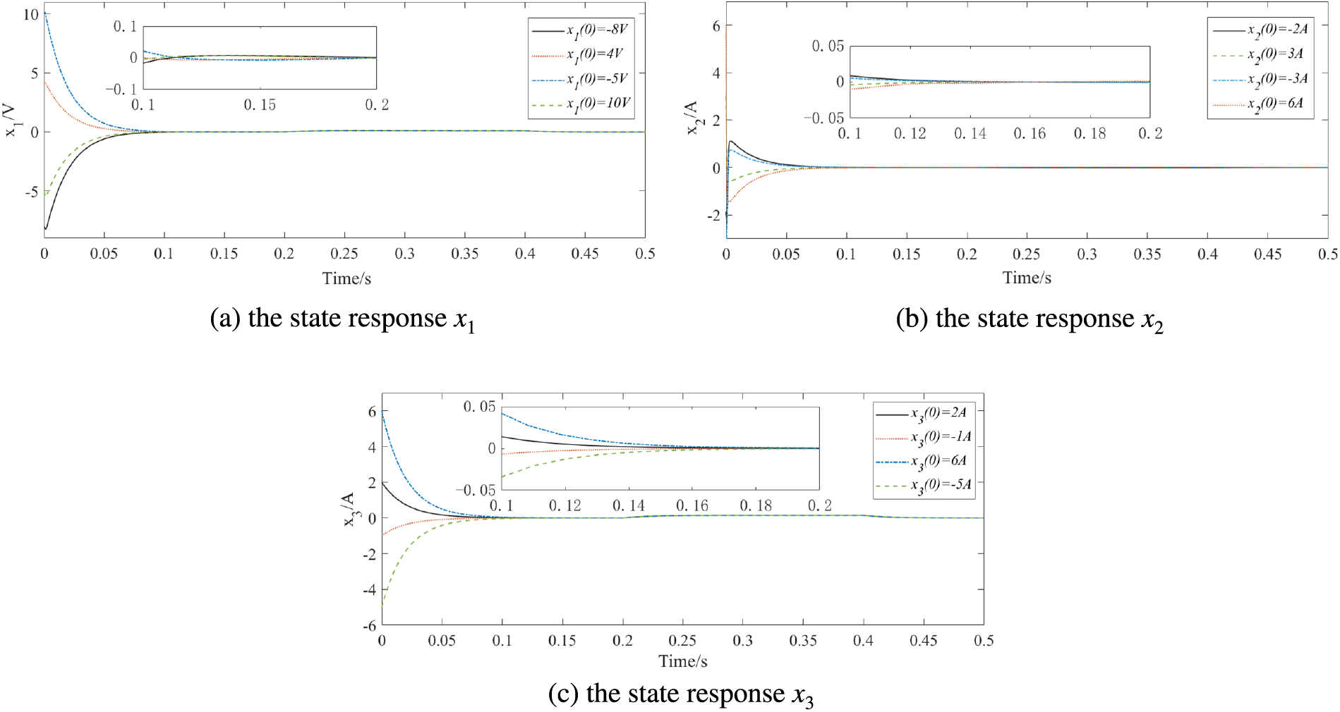
Figure 12: State responses under different initial states in fixed-time backstepping controller
Figs. 13–15 show the controllers’ trajectories in finite-time control, fixed-time control, and predefined-time control, respectively. Based on the simulation results, the predefined-time backstepping controllers and can achieve grid-connection objectives within the predefined time, effectively reduce the convergence time and improve the quality of grid-connected electrical energy.

Figure 13: Controllers under different initial states at

Figure 14: Controllers under different initial states in finite-time backstepping controller

Figure 15: Controllers under different initial states in fixed-time backstepping controller
To realize the effective control of VSI in a grid-connected PV system, a predefined-time controller is formulated. The time-varying functions are introduced in state tracking errors during the backstepping recursive design. Analytical differential calculation of the virtual control in backstepping control is avoided by the DSC strategy, and the disturbance compensation is realized by adaptive control. Furthermore, the global stability of the proposed predefined time control is verified by the Lyapunov theory. The simulation results demonstrate that the proposed predefined-time controller can implement predefined-time control and has excellent control performance for the inverter. The predefined time control method proposed in this paper can track the DC voltage and connect the unit power factor to the grid in the predefined time, but it depends on the initial states of the system, which should be solved in the future research.
Acknowledgement: Thanks to the editors and the anonymous reviewers for the helpful comments and suggestions that improve the presentation of the manuscript.
Funding Statement: This work was supported by the State Grid Corporation of China Headquarters Science and Technology Project under Grant No. 5400-202122573A-0-5-SF.
Author Contributions: The authors confirm contribution to the paper as follows: Dan Liu and Yanze Xu contributed to controller formulation. Kan Cao and Ping Xiong contributed to system stability analysis. Jiarui Zhang and Yunfei Mu wrote the manuscript and performed the simulations experiment. Xiaotong Ji contributed to the conception of the paper significantly. All authors reviewed the results and approved the final version of the manuscript.
Availability of Data and Materials: The authors confirm that the data supporting the findings of this study are available within the article. Additional data that support the findings of this study are available upon request from the corresponding author, subject to reasonable request.
Conflicts of Interest: The authors declare that they have no conflicts of interest to report regarding the present study.
References
1. J. Chen, Y. Lv, and T. Fan, “Research on the evolution and driving factors of digitalization of energy in China–A new perspective based on coupling coordination,” Heliyon, vol. 9, no. 3, May 2023. doi: 10.1016/j.heliyon.2023.e14138. [Google Scholar] [PubMed] [CrossRef]
2. D. Pullaguram, S. Mishra, and N. Senroy, “Event-triggered communication based distributed control scheme for DC microgrid,” IEEE Trans. Power Syst., vol. 33, no. 5, pp. 5583–5593, Sep. 2018. doi: 10.1109/TPWRS.2018.2799618. [Google Scholar] [CrossRef]
3. R. H. Lasseter, Z. Chen, and D. Pattabiraman, “Grid-forming inverters: A critical asset for the power grid,” IEEE J. Emerg. Sel. Top. Power Electron., vol. 8, no. 2, pp. 925–935, Dec. 2019. doi: 10.1109/JESTPE.2019.2959271. [Google Scholar] [CrossRef]
4. Y. X. Ji, W. He, S. J. Cheng, K. Jürgen, and M. Zhan, “Dynamic network characteristics of power-electronics-based power systems,” Sci. Rep., vol. 10, no. 1, pp. 9946, Jun. 2020. doi: 10.1038/s41598-020-66635-0. [Google Scholar] [PubMed] [CrossRef]
5. L. Zhang, Z. Chen, H. Zhang, Z. H. Ma, B. W. Cao and L. H. Song, “Accurate study and evaluation of small PV power generation system based on specific geographical location,” Energy Eng., vol. 117, no. 6, pp. 453–470, Aug. 2020. doi: 10.32604/EE.2020.013276. [Google Scholar] [CrossRef]
6. H. Abubakr, J. C. Vasquez, K. Mahmoud, M. M. F. Darwish, and J. M. Guerrero, “Comprehensive review on renewable energy sources in Egypt-current status, grid codes and future vision,” IEEE Access, vol. 10, pp. 4081–4101, Mar. 2022. doi: 10.1109/ACCESS.2022.3140385. [Google Scholar] [CrossRef]
7. F. Hasan, J. H. Ahmed, and N. K. Abdul Hadi, “Performance analysis of a rooftop hybrid connected solar PV system,” Energy Eng., vol. 119, no. 4, pp. 1729–1744, 2022. doi: 10.32604/ee.2022.021190. [Google Scholar] [CrossRef]
8. M. Inci, “Technoeconomic analysis of fuel cell vehicle-to-grid (FCV2G) system supported by photovoltaic energy,” Energy Technol., vol. 11, no. 4, pp. 2201162, Apr. 2023. doi: 10.1002/ente.202201162. [Google Scholar] [CrossRef]
9. M. İnci and K. Ç. Bayındır, “Single-stage vehicular fuel cell system with harmonic elimination capability to suppress distortion effects of electric vehicle parking lots,” J. Power Sources, vol. 597, pp. 234175, Mar. 2024. doi: 10.1016/j.jpowsour.2024.234175. [Google Scholar] [CrossRef]
10. M. İnci, “Connecting multiple vehicular PEM fuel cells to electrical power grid as alternative energy sources: A case study,” Int. J. Hydrogen Energy, vol. 52, pp. 1035–1051, Jan. 2024. doi: 10.1016/j.ijhydene.2023.08.228. [Google Scholar] [CrossRef]
11. X. Deng, F. P. Da, H. J. Shao, and X. Wang, “A survey of the researches on grid-connected solar power generation systems and power forecasting methods based on ground-based cloud atlas,” Energy Eng., vol. 120, no. 2, pp. 385–408, Jul. 2023. doi: 10.32604/ee.2023.023480. [Google Scholar] [CrossRef]
12. D. Z. Xu, Y. C. Dai, C. S. Yang, and X. G. Yan, “Adaptive fuzzy sliding mode command-filtered backstepping control for islanded PV microgrid with energy storage system,” J. Frank. Inst. Eng. Appl. Math., vol. 356, no. 4, pp. 1880–1898, Mar. 2019. doi: 10.1016/j.jfranklin.2019.01.012. [Google Scholar] [CrossRef]
13. X. Shi, Y. Cheng, C. Yin, X. Huang, and S. M. Zhong, “Design of adaptive backstepping dynamic surface control method with RBF neural network for uncertain nonlinear system,” Neurocomputing, vol. 330, pp. 490–503, Feb. 2019. doi: 10.1016/j.neucom.2018.11.029. [Google Scholar] [CrossRef]
14. S. Dhar and P. K. Dash, “Adaptive backstepping sliding mode control of a grid interactive PV-VSC system with LCL filter,” Sustain. Energy, Grids Netw., vol. 6, pp. 109–124, Jun. 2016. doi: 10.1016/j.segan.2016.03.001. [Google Scholar] [CrossRef]
15. Z. X. Zhong, X. Y. Wang, and H. K. Lam, “Finite-time fuzzy sliding mode control for nonlinear descriptor systems,” IEEE/CAA J. Autom. Sin., vol. 8, no. 6, pp. 1141–1152, Jun. 2021. doi: 10.1109/JAS.2021.1004024. [Google Scholar] [CrossRef]
16. El. J. Khazane and E. H. Tissir, “Achievement of MPPT by finite time convergence sliding mode control for photovoltaic pumping system,” Sol. Energy, vol. 166, pp. 13–20, May 2018. doi: 10.1016/j.solener.2018.03.026. [Google Scholar] [CrossRef]
17. M. Y. Xie, M. M. Gulzar, H. Tehreem, M. Y. Javed, and S. T. H. Rizvi, “Automatic voltage regulation of grid connected photovoltaic system using Lyapunov based sliding mode controller: A finite-time approach,” Int. J. Control Autom. Syst., vol. 18, pp. 1550–1560, Jun. 2020. doi: 10.1007/s12555-019-0563-x. [Google Scholar] [CrossRef]
18. P. Zhang, G. R. Zhang, and H. B. Du, “Finite-time consensus for power regulation of parallel PV Grid-connected inverters,” IEEE Trans. Circuits Syst. II-Express Briefs, vol. 67, no. 11, pp. 2632–2636, Nov. 2020. doi: 10.1109/TCSII.2020.2964956. [Google Scholar] [CrossRef]
19. S. Dhar and P. K. Dash, “A new backstepping finite time sliding mode control of grid connected PV system using multivariable dynamic VSC model,” Int. J. Electr. Power& Energy Syst., vol. 82, pp. 314–330, Nov. 2016. doi: 10.1016/j.ijepes.2016.03.034. [Google Scholar] [CrossRef]
20. C. S. Yang, S. F. Ni, Y. C. Dai, X. N. Huang, and D. D. Zhang, “Anti-disturbance finite-time adaptive sliding mode backstepping control for PV inverter in master-slave-organized islanded microgrid,” Energies, vol. 13, no. 17, pp. 4490, Sep. 2020. doi: 10.3390/en13174490. [Google Scholar] [CrossRef]
21. W. Y. Jiang, S. S. Ge, and D. Y. Li, “Fixed-time-synchronized control: A system-dimension-categorized approach,” Sci. China Inf. Sci., vol. 66, no. 7, pp. 1–18, Jul. 2023. doi: 10.1007/s11432-022-3649-1. [Google Scholar] [CrossRef]
22. L. N. Liu and G. H. Yang, “Distributed fixed-time optimal resource management for microgrids,” IEEE Trans. Autom. Sci. Eng., vol. 20, no. 1, pp. 404–412, Jan. 2022. doi: 10.1109/TASE.2022.3155163. [Google Scholar] [CrossRef]
23. S. Shi, G. S. Zhang, H. F. Min, Y. L. Hu, and Y. H. Sun, “Exact uncertainty compensation of linear systems by continuous fixed-time output-feedback controller,” J. Syst. Eng. Electron., vol. 33, no. 3, pp. 706–715, Jun. 2022. doi: 10.23919/JSEE.2022.000065. [Google Scholar] [CrossRef]
24. L. Y. Xiong et al., “Voltage and frequency regulation with WT-PV-BESS in remote weak grids via fixed-time containment control,” IEEE Trans. Power Syst., vol. 38, pp. 2719–2735, May 2023. doi: 10.1109/TPWRS.2022.3190847. [Google Scholar] [CrossRef]
25. S. Sahoo, S. Mishra, S. Fazeli, F. R. Li, and T. Dragicevic, “A distributed fixed-time secondary controller for DC microgrid clusters,” IEEE Trans. Energy Convers., vol. 34, no. 4, pp. 1997–2007, Dec. 2019. doi: 10.1109/TEC.2019.2934905. [Google Scholar] [CrossRef]
26. Y. N. Pan, W. Y. Ji, and H. J. Liang, “Adaptive predefined-time control for Lü chaotic systems via backstepping approach,” IEEE Trans. Circuits Syst. II: Express Briefs, vol. 69, no. 12, pp. 5064–5068, Dec. 2022. doi: 10.1109/TCSII.2022.3204050. [Google Scholar] [CrossRef]
27. R. E. Jiménez, T. J. D. Sánchez, G. D. Gómez, and A. G. Loukinanov, “Variable structure predefined-time stabilization of second-order systems,” Asian J. Control, vol. 21, no. 3, pp. 1179–1188, May 2019. doi: 10.1002/asjc.1785. [Google Scholar] [CrossRef]
28. Y. Zhang, Y. W. Wang, J. W. Xiao, and X. K. Liu, “Predefined-time secondary control for DC microgrid,” IEEE Trans. Ind. Electron., vol. 69, no. 12, pp. 13504–13513, Dec. 2021. doi: 10.1109/TIE.2021.3128899. [Google Scholar] [CrossRef]
29. F. L. Jia, J. Huang, and X. He, “Adaptive predefined-time tracking control for high-order strict-feedback nonlinear systems with unknown mismatched disturbances,” Int. J. Adapt Control Signal Process, vol. 36, no. 11, pp. 2903–2919, Sep. 2022. doi: 10.1002/acs.3502. [Google Scholar] [CrossRef]
30. J. A. Moreno, “Arbitrary-order fixed-time differentiator,” IEEE Trans. Automat. Contr., vol. 67, no. 3, pp. 1543–1549, May 2022. doi: 10.1109/TAC.2021.3071027. [Google Scholar] [CrossRef]
31. D. Xu, G. Wang, W. Yan, and C. Shen, “Nonlinear adaptive command-filtered backstepping controller design for three-phase grid-connected solar photovoltaic with unknown parameters,” presented at the 2017 Chinese Autom. Congr., Jinan, China, Oct. 20–22, 2017, pp. 7823–7827. [Google Scholar]
32. R. E. Jiménez, V. A. Muñoz, T. J. D. Sánchez, M. Defoort, and A. G. Loukianov, “A Lyapunov-like characterization of predefined-time stability,” IEEE Trans. Automat. Contr., vol. 65, no. 11, pp. 4922–4927, Nov. 2020. doi: 10.1109/TAC.2020.2967555. [Google Scholar] [CrossRef]
33. C. Song, H. B. Sun, and L. L. Hou, “A predefined time decentralized adaptive tracking control method for interconnected nonlinear systems,” Int. J. Robust Nonlinear Control, vol. 33, no. 13, pp. 7986–8014, Sep. 2023. doi: 10.1002/rnc.6806. [Google Scholar] [CrossRef]
34. H. Bécerra, C. Vázquez, G. Arechavaleta, and J. Delfin, “Predefined-time convergence control for high-order integrator systems using time base generators,” IEEE Trans. Control Syst. Technol., vol. 26, no. 5, pp. 1866–1873, Sep. 2018. doi: 10.1109/TCST.2017.2734050. [Google Scholar] [CrossRef]
35. B. J. Liu, M. S. Hou, C. H. Wu, W. C. Wang, Z. H. Wu and B. Huang, “Predefined-time backstepping control for a nonlinear strict-feedback system,” Int. J. Robust Nonlinear Control, vol. 31, no. 8, pp. 3354–3372, Feb. 2021. doi: 10.1002/rnc.5425. [Google Scholar] [CrossRef]
Cite This Article
 Copyright © 2024 The Author(s). Published by Tech Science Press.
This work is licensed under a Creative Commons Attribution 4.0 International License , which permits unrestricted use, distribution, and reproduction in any medium, provided the original work is properly cited.


 Submit a Paper
 Propose a Special lssue
 View Full Text
 Download PDF
 Downloads
 Citation Tools