
 Submit a Paper
 Propose a Special lssue
 Open Access
ARTICLE

Lithium-Ion Battery Pack Based on Fuzzy Logic Control Research on Multi-Layer Equilibrium Circuits
Faculty of Electrical and Electronic Engineering, Hubei University of Technology, Wuhan, China
* Corresponding Author: Yukan Zhang. Email:
(This article belongs to the Special Issue: Advanced Modelling, Operation, Management and Diagnosis of Lithium Batteries)
Energy Engineering 2024, 121(8), 2231-2255. https://doi.org/10.32604/ee.2024.049883
Received 21 January 2024; Accepted 18 March 2024; Issue published 19 July 2024
 View Full Text
 Download PDF
Abstract
In order to solve the problem of inconsistent energy in the charging and discharging cycles of lithium-ion battery packs, a new multilayer equilibrium topology is designed in this paper. The structure adopts a hierarchical structure design, which includes intra-group equilibrium, primary inter-group equilibrium and secondary inter-group equilibrium. This structure greatly increases the number of equilibrium paths for lithium-ion batteries, thus shortening the time required for equilibrium, and improving the overall efficiency. In terms of control strategy, fuzzy logic control (FLC) is chosen to control the size of the equilibrium current during the equilibrium process. We performed rigorous modeling and simulation of the proposed system by MATLAB and Simulink software. Experiments show that the multilayer equilibrium circuit structure greatly exceeds the traditional single-layer equilibrium circuit in terms of efficacy, specifically, the Li-ion battery equilibrium speed is improved by 12.71% in static equilibrium, 14.48% in charge equilibrium, and 11.19% in discharge equilibrium. In addition, compared with the maximum value algorithm, the use of the FLC algorithm reduces the equalization time by about 3.27% and improves the energy transfer efficiency by about 66.49% under the stationary condition, which verifies the feasibility of the equalization scheme.Keywords
Lithium-ion batteries have the advantages of high energy density, high conversion efficiency, long cycle life, no memory effect, no charging/discharging delay, low self-discharge rate, wide operating temperature range, and environmental friendliness, and thus are widely used in new energy vehicles [1]. Since the voltage of a single battery is low and insufficient to meet the power demand of electric vehicles, multiple batteries are usually connected in series to form a battery pack for use [2]. However, factors such as varying internal resistances, unequal capacities, aging, and changes in environmental temperature result in inconsistency among the batteries in the pack [3], which affects the performance and lifespan of the battery pack. To extend the lifespan of the battery pack, it is crucial to implement battery pack balancing [4].
Battery balancing circuits can be classified into two types based on whether they consume energy: Passive balancing and active balancing. Passive balancing dissipates the excess energy from high-energy cells through parallel resistors, achieving balance by consuming energy [5]. It has the advantage of being structurally simple and cost-effective but suffers from high energy loss [6]. On the other hand, active balancing transfers the excess energy from high-energy cells to low-energy cells using non-energy-consuming energy storage components such as capacitors, inductors, transformers, and direct current to direct current (DC-DC) converters [7]. Among them, the use of inductors as intermediate energy storage elements in balancing circuits has the advantages of high balancing current and easy circuit scalability [8]. In literature [9], invention of a free-combination hierarchical balancing technique on the basis of a buck-boost circuit with switched inductor, which enables balancing between any combination of batteries. However, it involves significant switch losses and results in low energy utilization. Literature [10] designs a new hierarchical balancing topology using inductors and flyback transformers, overcoming the limitation of traditional inductors that can only balance adjacent cells. However, this approach has higher transformer costs and complex control. In literature [11], an improved Buck-Boost structure is used to achieve energy transfer between the first and last cells. Literature [12] proposes simultaneous intra-group and inter-group balancing and hierarchical balancing strategies based on hierarchical balancing circuits, providing a foundation for the study of hierarchical balancing strategies in this paper.
Regarding the equalization control strategy, it means that the equalization variable is used as the judgment basis of whether the battery pack achieves consistency or not. Among the various equalization control strategies, the maximum value equalization method is simple to implement for battery equalization but lacks efficiency [13]. The mean and difference comparison methods use the average capacity of all individual cells in the battery bank as a reference. However, they are only applicable when a small number of battery banks are involved. When equalizing individual cells requires energy transfer between multiple cells, this results in less efficient equalization. Equalization is achieved using FLC, which is more effective in optimizing the equalization efficiency [14]. In this paper, the FLC algorithm [15], which does not require an accurate mathematical model, is used to improve the inconsistency of the cells and optimize the equalization efficiency by taking advantage of its strong nonlinearity, robustness, and fault tolerance.
In conclusion, to address the issues of slow balancing speed and long balancing time in the equalization circuit, this paper combines the Buck-Boost structure and multi-layered topology in the switch-inductor method. It proposes a lithium-ion battery hierarchical balancing technique based on the Buck-Boost circuit and utilizes the battery state of charge (SOC) value as the criterion to determine whether the equalization system should be activated. The battery pack is divided into hierarchical groups, and different balancing control methods are applied to each group based on their grouping. The fuzzy logic balancing strategy is used to balance the battery group.
2 Equalization Circuit Structure Analysis
2.1 The Principle of Equilibrium
As shown in Fig. 1, the equalization of the batteries in the group is completed by a bidirectional Buck-Boost equalization circuit. Taking B1 and B2 batteries as an example, when the energy of B1 is higher than that of B2, the MOSFET is turned on and off by pulse width modulation (PWM) to realize the transfer of energy, and the whole equalization process is divided into two phases, and the working principle of the Buck-Boost mode is shown in Fig. 1.
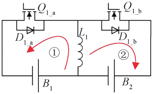
Figure 1: Buck-Boost equalization circuit current loop
Stage 1) B1 discharges as follows: The SOC of B1 is higher than that of B2, the control module sends out a signal, and the switch Q1_a is turned on. The loop consists of B1, L1, and Q1_a. B1 charges inductor L1, and the current in inductor L1 gradually increases. The electrical energy in B1 is stored in inductor L1 in the form of magnetic energy, and at a certain point the controller sends out a signal, switch Q1_a is disconnected, and the equalization current reaches the peak . The current of L1 is calculated as shown in Eq. (1).
(1)
During the whole cycle, the maximum current in the inductor is shown in Eq. (2).
(2)
In the formula: D is the duty cycle of the switch drive control signal; Ts is the period of the switch control signal.
Stage 2) The charging process of B2 is as follows: When Q1_a is disconnected, the continuity diode D1_b conducts, the magnetic energy stored in L1 is converted into electrical energy, and a closed circuit is formed by B2, L1, and D1_b. The current gradually decreases from the peak value, and the voltage decreases until the voltage at the L1 end is lower than the sum of the voltages of B2 and D1_b, then the equalization current decreases to 0, and the charging process of B2 ends. After several cycles of charging and discharging, the excess power in B1 is transferred to B2 to realize battery equalization. The current of inductor L1 is calculated as shown in Eq. (3).
(3)
The energy transferred from B1 to B2 during the entire cycle is shown in Eq. (4).
(4)
The experimental object of this lithium-ion battery equilibrium experiment is 8 lithium-ion batteries. The framework of the inductor-based multilayer equilibrium circuit proposed in this study is shown in Fig. 2.
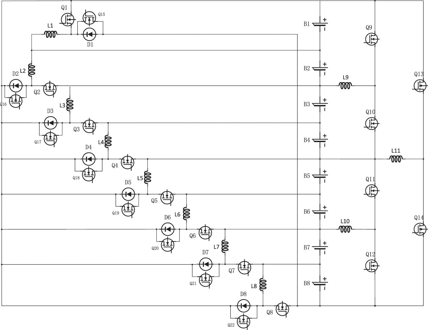
Figure 2: Inductor-based multilayer equilibrium circuit structure
2.2.1 Intra-Group Equilibrium Circuitry
The framework of the intra-group equilibrium is illustrated in Fig. 3.
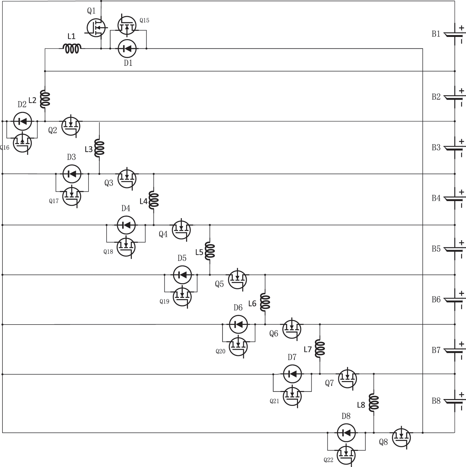
Figure 3: Within-group equilibrium circuit structure
The initiation threshold for the group balance switch tube is defined at a 5% margin. This means should the variance between the uppermost and lowermost SOC levels of an individual lithium-ion battery be in excess of 5%, the switch tube will activate. If the SOC variance falls below this threshold, the switch tube will remain inactive.
Suppose that when the SOC of lithium-ion battery cell B1 is the highest, and the difference between the SOC of B1 and the SOC of the cell with the smallest SOC in the lithium-ion battery pack is greater than 5%, the switch tube Q1 is turned on, B1 charges the energy storage inductor L1 (as shown by the red arrow in Fig. 4), after the charging is over, the switch tube Q1 is turned off, and the energy storage inductor L1 charges the lithium-ion batteries B2-B8 to complete the energy transfer (as shown by the blue arrow in Fig. 4).
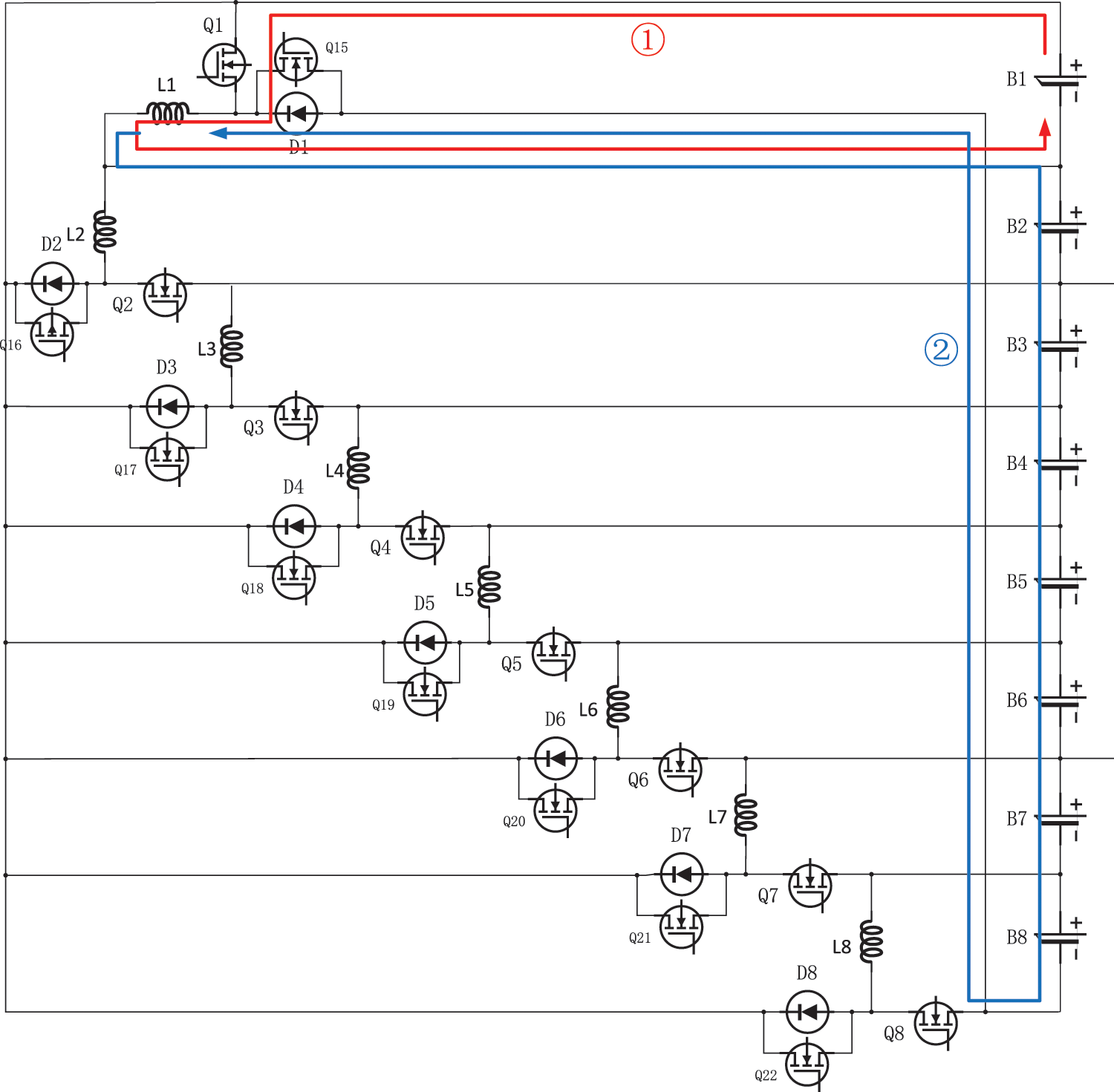
Figure 4: Lithium-ion battery B1 charging and discharging equilibrium process
When the SOC value of the lithium-ion battery BX (X is a positive integer of 2-8) other than B1 is the highest, and the difference between the highest and lowest values of the SOC of the batteries in the battery pack is greater than 5%, the switch tube QX is turned on, and the battery Bi charges the energy storage inductor LX (as shown by the red arrow in Fig. 5, where X is assumed to be 5), after the charging is over, the switch QX is turned off, and the energy storage inductor LX charges the lithium-ion batteries B1-BX-1 to complete the energy transfer (as shown by the blue arrow in Fig. 5).
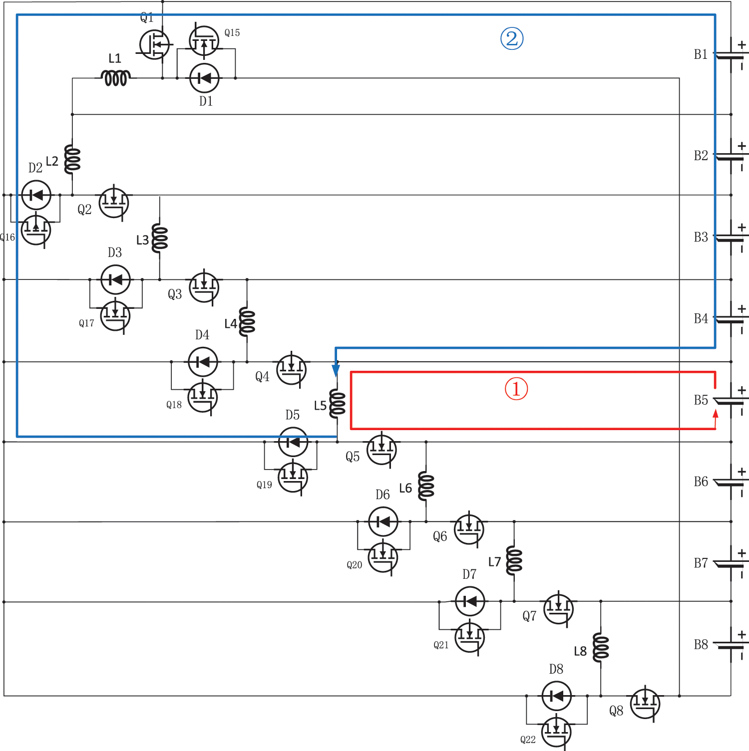
Figure 5: Lithium-ion battery B5 charging and discharging equilibrium process
2.2.2 Inter-Group Equilibrium Circuits
The overall framework of inter-group equilibrium is shown in Fig. 6, for the inter-pack equilibrium of lithium-ion batteries, an inductor-based two-stage circuit equalization structure is designed using the buck-boost principle: First, the first-stage inter-pack equilibrium of lithium-ion batteries is divided into four groups, B1 and B2 are the first group, B3 and B4 are the second group, B5 and B6 are the third group, and B7 and B8 are the fourth group. The first group of lithium-ion battery packs and the second group of lithium-ion battery packs are cell equalized, and the third group of lithium-ion battery packs and the fourth group of lithium-ion battery packs are cell balanced. Wait until the first-level inter-group equilibrium is completed, start the second-level inter-group equilibrium, and divide the lithium-ion battery pack into two groups, the lithium-ion battery B1-B4 is the first group, and the lithium-ion battery B5-B8 is the second group, The cells are then equalized between these two lithium-ion battery packs. Using two-stage lithium-ion battery pack equilibrium improves the energy utilization of lithium-ion batteries and speeds up equilibrium.
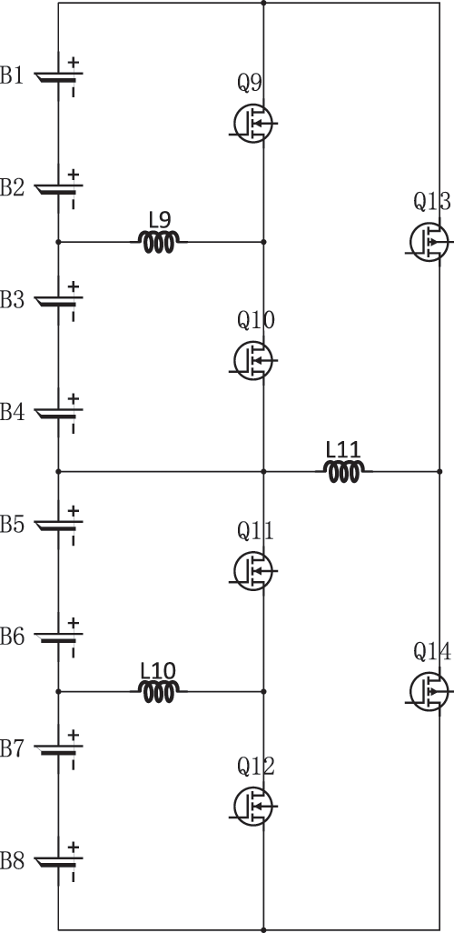
Figure 6: Inter group equilibrium circuit structure
When equilibrium between the first level groups, the conduction threshold of the switching transistor is 2.5%. Let us consider the scenario where the mean SOC of the initial lithium-ion battery pack exceeds that of the second lithium-ion battery pack by a margin exceeding 2.5%, and similarly, the mean SOC of the lithium-ion third battery pack surpasses the mean SOC of the fourth lithium-ion battery pack by over 2.5%, the switching transistor Q9 and switching transistor Q11 conduct. Battery pack one and battery pack three charge the energy storage inductors L9 and L10 respectively (as shown by the red arrow in Fig. 7). After the energy storage inductor is fully charged, turn off Q9 and Q11, and open Q10 and Q12. The energy storage inductor, designated L9, is responsible for charging the second set of lithium-ion battery packs, while the energy storage inductor, marked as L10, serves to charge the fourth set of lithium-ion battery packs (as shown by the blue arrow in Fig. 7).
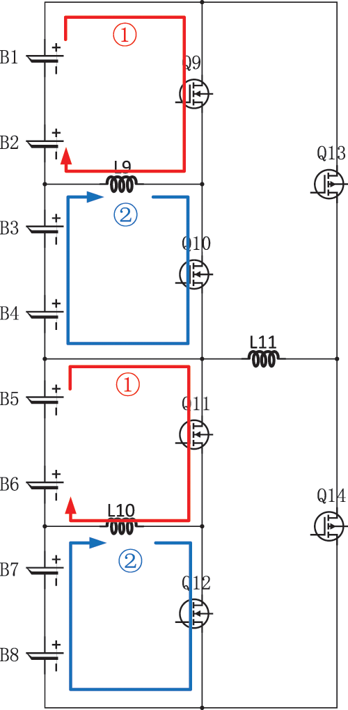
Figure 7: First-level inter-group equilibrium process
When equilibrium between groups in the second stage, the lithium-ion batteries are divided into two groups. Lithium-ion battery groups B1-B4 are the first group, and lithium-ion battery packs B5-B8 are the second group. Assuming that the mean SOC value of the first lithium-ion battery pack is 1% higher than the mean SOC value of the second lithium-ion battery pack, switch Q13 is energized, and the first group of batteries (B1-B4) starts charging the energy storage inductor L11 (as shown by the red arrow in Fig. 8). After charging is completed, switch Q13 closes, switch Q14 conducts, and energy storage inductor L11 charges the second group of batteries (B5-B8) (as shown by the blue arrow in Fig. 8).
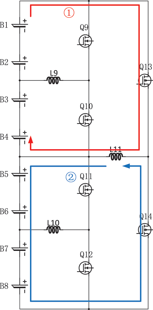
Figure 8: Secondary inter-group equilibrium process
2.3 Conventional Two-Layer Equalization Circuit Simulation Structure
In order to verify the superiority of the multilayer equilibrium circuit structure in lithium-ion battery equilibrium, a traditional double-layer equilibrium circuit is used in this paper to carry out a comparison test [16], as shown in Fig. 9.
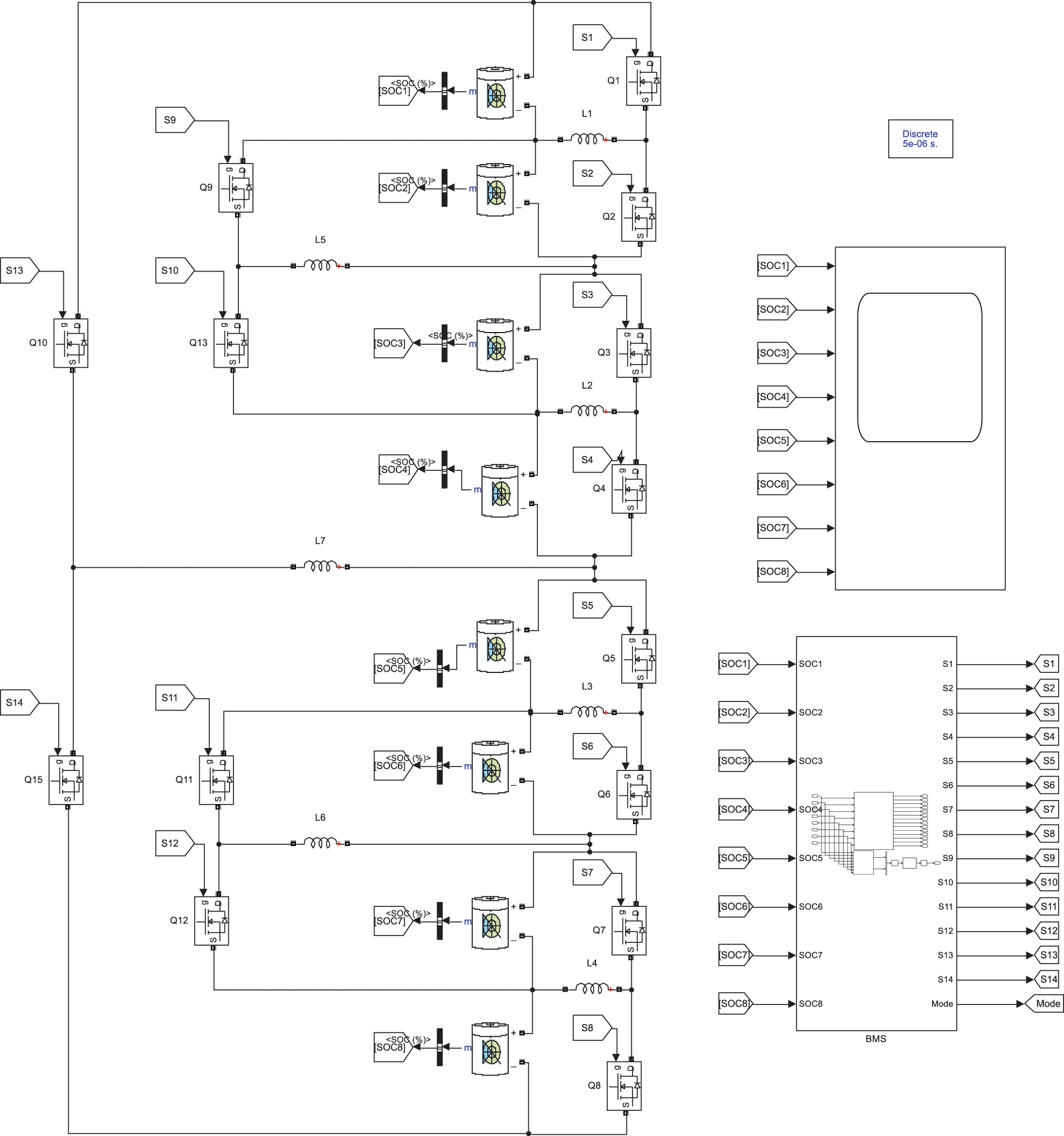
Figure 9: Traditional double-layer balanced circuit structure
3 Balanced Strategy Based on FLC
In this study, the SOC of the Lithium-ion battery is used as a reference parameter for the equilibrium process. Once the difference between the highest and lowest SOC values between Lithium-ion batteries (Lithium-ion battery packs) exceeds a predetermined threshold, the circuit starts to perform equilibrium [17]. The method designed in this paper is a layer-by-layer equilibrium technique: Firstly, intra-group equilibrium is performed until the difference in SOC between each Lithium-ion battery is less than the intra-group equilibrium threshold. Then, after completing the intra-group equilibrium, the first level of inter-group equilibrium is started [18], until the difference of SOC between each lithium-ion battery group is less than the first level of inter-group equilibrium threshold. Finally, after completing the first-level inter-group equilibrium, the second-level inter-group equilibrium is started until the difference of SOC between each lithium-ion battery group is less than the second-level inter-group equilibrium threshold, and the equilibrium is finished. In each stage of equilibrium, the lithium-ion batteries (lithium-ion battery packs) can be equalized at the same time, and this method can increase the number of equilibrium channels, thereby improving the energy transfer efficiency and shortening the time required for equilibrium [19]. The program flow of this specific equilibrium method is shown in Fig. 10.
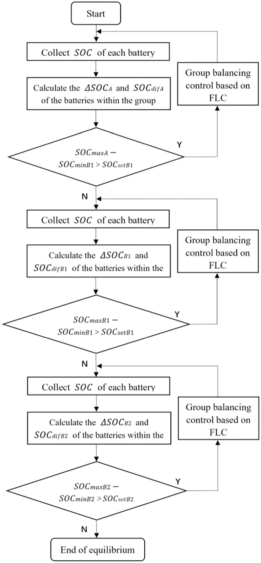
Figure 10: Flowchart of the equilibrium process based on FLC
In Fig. 10, and represent the initial highest and lowest SOC values in a single cell during intra-group equilibrium, respectively. Similarly, and correspond to the initial highest and lowest SOC values of the lithium-ion battery pack during primary intergroup equilibrium of the lithium-ion battery pack, and and correspond to the initial highest and lowest SOC values of the lithium-ion battery pack during secondary intergroup equilibrium of the lithium-ion battery pack. The equilibrium thresholds for intra-group equilibrium, primary inter-group equilibrium, and secondary inter-group equilibrium are defined as , and , which are scheduled to be 5%, 2.5%, and 1%, respectively [20].
Due to the natural differences in capacity and inner impedance of individual cells in a battery group, constructing a precise and dependable mathematical model presents a substantial challenge. Thus, this study advocates the use of FLC as a strategy for SOС-based equilibrium methods. FLC is an intelligent control algorithm that operates independently of the mathematical model and is remarkably robust, making it well-suited for nonlinear and time-varying systems.
The control strategy described in this study involves three different types of FLCs: Intra-group FLC, primary inter-group FLC, and secondary inter-group FLC. Despite the different application environments, the rules and the affiliation functions of these FLCs are the same [21], so the following is an example of intra-group FLC.
(5)
(6)
(7)
(8)
In Eqs. (5)–(8), and represent the single cell battery with the highest and lowest SOC values, respectively. is the mean SOC of lithium-ion batteries, is the mean value of the single cell battery with the highest and lowest SOC values, is the difference in charge state between the balanced battery and the entire battery group, is the difference between the individual cells with the highest and lowest SOC values in a single lithium-ion battery [22].
3.2 Design of Fuzzy Logic Controller
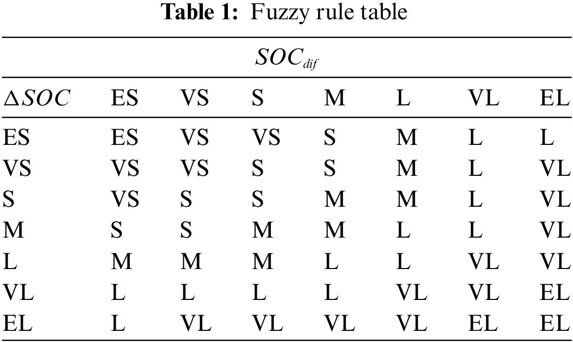
In this part of the study, we will detail the design of the FLC. The controller generates a balancing current, denoted as , which we limit to [0,5] amperes to ensure that the battery will not be affected by high currents during the balancing process, which can shorten the lifetime of the battery. We use and as input variables for FLC and set the value ranges of and to (0%, 20%) and (0%, 80%) sequentially according to their value ranges. Through the fuzzification process, the input variables are transformed into fuzzy characters, denoted as (x) and (y), respectively. Subsequently, they are categorized into seven fuzzy subsets: Extremely small (ES), very small (VS), small (S), medium (M), large (L), very large (VL), and extremely large (EL). Based on the practical experience of battery balance control, we established a fuzzy rule table as shown in Table 1.
Drawing insights from the established fuzzy rule table, we can infer specific strategies for control:
(1) A substantial equilibrium current is advocated when both the and the are considerable, with the objective of diminishing the time required for equilibrium and expediting the equilibrium process.
(2) Conversely, when both the and the are minimal, it is prudent to apply a minimal equilibrium current. This cautionary measure helps avert the risk of overcharging the cells, thus ensuring the safety of the battery.
(3) In instances where the and the are of moderate magnitudes, an intermediate equilibrium current is deemed appropriate.
The decision to employ a triangular membership function in this study is attributed to its straightforward computational approach and the efficacy of the control outcomes it yields. The fuzzy control membership functions predicated upon SOC are depicted in Figs. 11–13 [23].
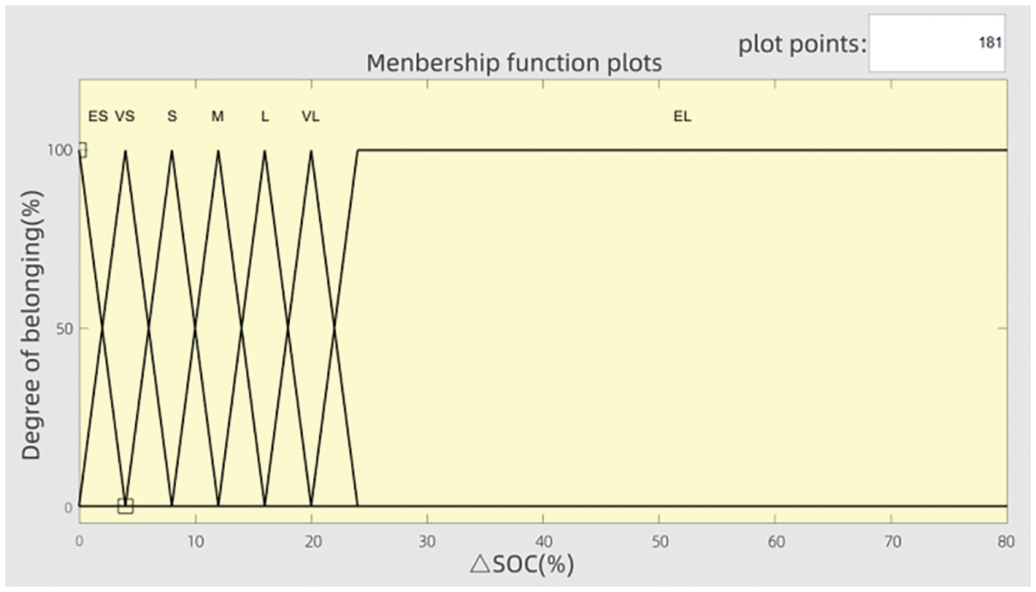
Figure 11: membership function
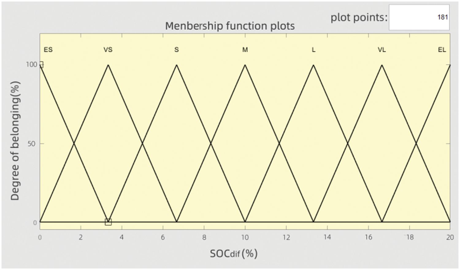
Figure 12: membership function
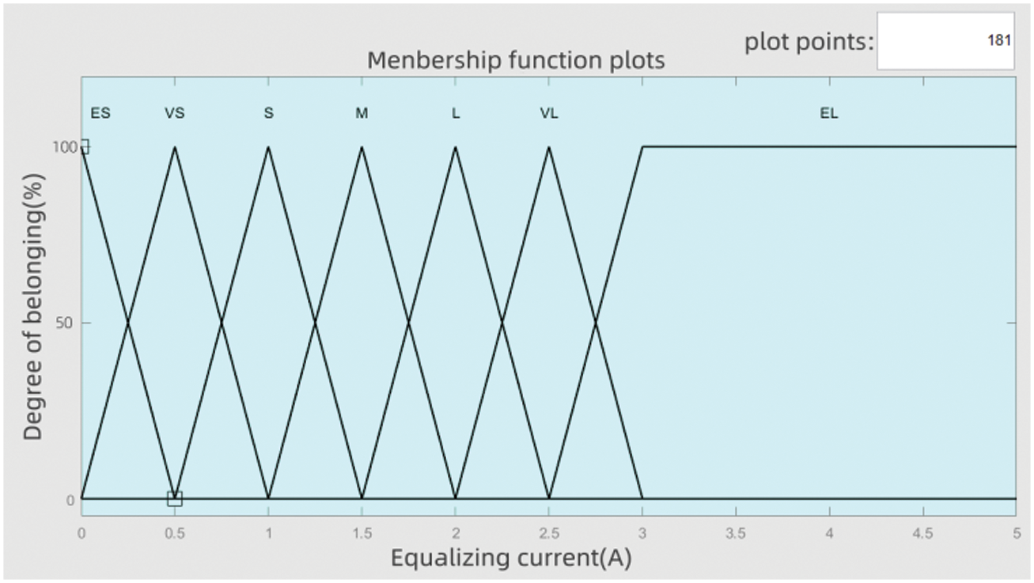
Figure 13: membership function
Based on the output fuzzy control rule table, we can obtain the following three-dimensional fuzzy control diagram. The x-axis of this 3D fuzzy control diagram is , and the y-axis is , the z-axis is the equilibrium current , and through the three-dimensional fuzzy control diagram (as shown in Fig. 14), we can more intuitively see the effect of FLC.
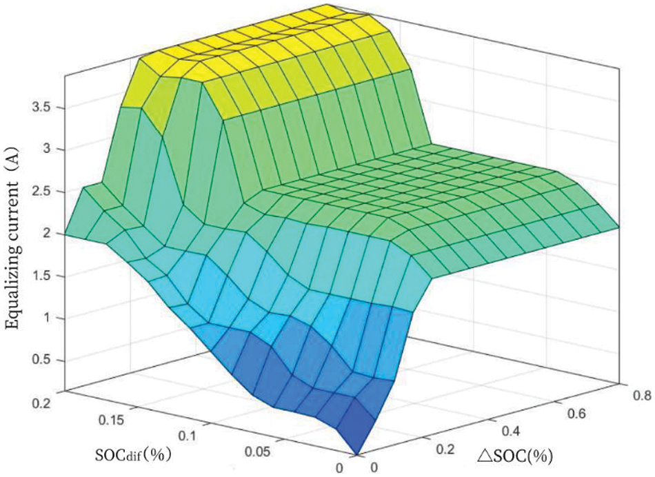
Figure 14: Fuzzy rule 3D graph
The fuzzy outcomes generated by the inference engine are not directly applicable as control signals for the switching transistor, necessitating a defuzzification process to convert them into usable signals. In this instance, the defuzzification process utilizes the centroid manner, as articulated in Eq. (9) [24]:
(9)
Within the equation, (z) represents the outcome of the fuzzy inference process. The equilibrium current, as determined by the fuzzy logic controller, is utilized to calculate the appropriate switching period. Subsequently, this timing is used to manage the equilibrium circuit by regulating the MOSFET [25].
4 Simulation Experiment Analysis
4.1 Parameter Calculation of Equalization Circuit
In order to maximize the energy utilization when discharging the inductor, the circuit needs to work in discontinuous current mode (DCM) [26], so this time to calculate the maximum value of duty cycle D. Take the example of energy transfer from battery B2 to B1, the equalization current is shown in Fig. 15 below.
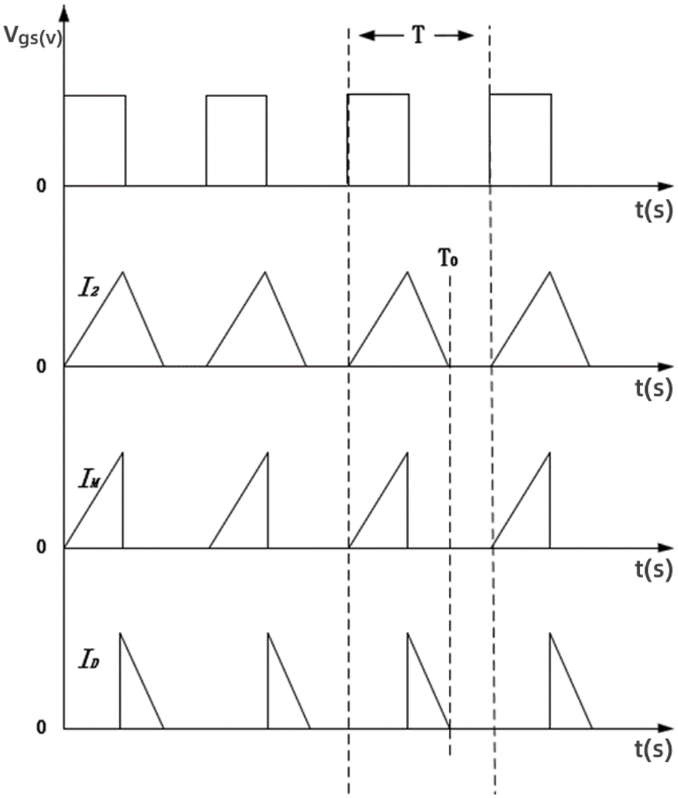
Figure 15: Current waveform graph
Vgs is the driving signal of the switching tube; I2 is the current of the inductor in one cycle; IM is the current flowing through the open phototube; ID is the current flowing through the diode. When the field-effect transistor is on, the battery current flows through the corresponding inductor. When the switching frequency is high, the current rises approximately linearly and the inductor is charged to store energy. According to the figure above, the inductor current in one cycle of the switching tube is I2 as shown in Eq. (10) below [27]:
(10)
where T0 is the moment when the inductor current is 0; V2 is the voltage across inductor L2 when switching tube Q2 is on. is the voltage across the inductor when the switching tube Q2 is turned off; T is the switching period and D is the duty cycle.
From the working principle of the single cell battery equalization sub-circuit, it is known that the ratio of voltage to energy is maximum when cell B2 transfers energy to cell B1, and the duty cycle D is calculated as the maximum value [28]. In this paper, because the battery equalization is based on voltage, a capacitor is used instead of the battery, and the capacity of the capacitor is 3300E-6F. The duty cycle of the switching tubes is calculated to be no greater than 0.45, so the constant duty cycle of the switching tubes of the multilayer lithium-ion battery equalization circuit designed in this paper is set to 0.45 under the FLC strategy. The PWM transient drive waveform for the current is shown in Fig. 16.
Figure 16: Equalization current variation at 45% duty cycle
4.2 Analysis of Simulation Experiment Results
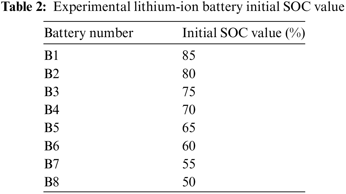
In this paper, eight lithium-ion batteries are selected as experimental objects, and the initial SOC values of the eight lithium-ion batteries are shown in Table 2, the initial mean SOC value of the lithium-ion battery pack was 67.5%, the rated voltage of a single lithium-ion battery is 3.7 V, the upper cutoff voltage is 4.2 V, the rated capacity is 5400 mAh, and the switching frequency is 8 kHz. The value of inductance is calculated according to Eq. (11). In Eq. (11), is the voltage of 8 batteries in series, according to the nominal voltage of 3.7 V to calculate 29.6 V, T is the reciprocal of the switching frequency f, switching frequency is set to 50 kHz, the maximum value of equalization current is 5A, the current ripple is about 40%, So the value of is 2A, inductance is greater than 296 μH can be. The inductance value of 330 μH is selected under comprehensive consideration.
(11)
4.2.1 Validation of FLC Algorithm
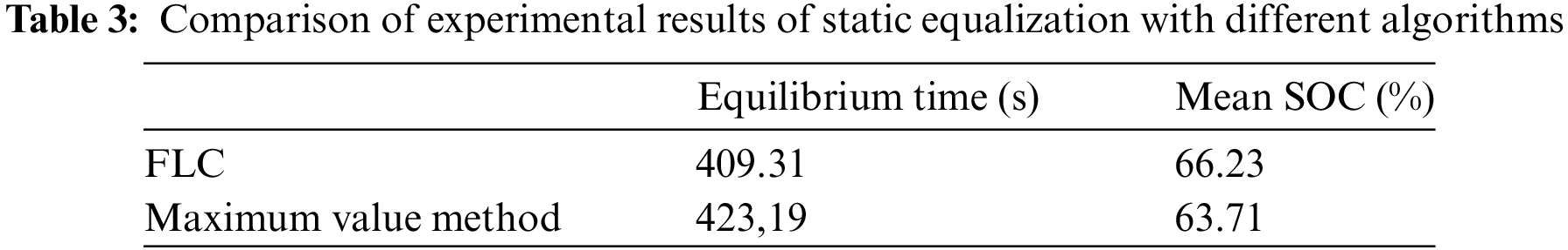
In order to demonstrate the advantages of the FLC algorithm proposed in this paper, we conducted a comparison experiment with the maximum algorithm. Figs. 17a and 17b show the SOC change lines for each cell after the use of the FLC-based algorithm and the maximum-based equalization method, respectively.
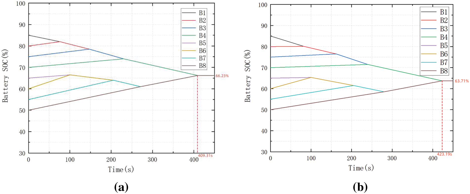
Figure 17: (a) FLC static equalization. (b) Maximum value method of static equalization
As shown in Table 3, it takes 423.19 s to equalize the battery pack using the maximum value method, while it takes 409.31 s using the FLC algorithm, so the FLC algorithm is relatively 3.27% faster in the equalization time. Based on the average initial SOC and average equilibrium SOC of the lithium-ion battery pack, it can be concluded that the FLC algorithm used in this paper improves the energy transfer efficiency by 66.49% over the maximum value algorithm.
Compared to the maximization method equilibrium strategy, the battery charging and discharging currents do not exceed the permissible values when the battery pack is operated under larger external currents, which indicates that the proposed FLC equalization strategy has better performance. The equalization currents of the Li-ion battery equalization circuit using the FLC algorithm are shown in Fig. 18, where I1-I8 are the equalization currents of eight Li-ion batteries in the equalization process. Experiments show that the equalization current varies with the change of battery SOC when the FLC algorithm is used, which can effectively prevent the battery temperature from increasing and keep the battery working normally at all times.
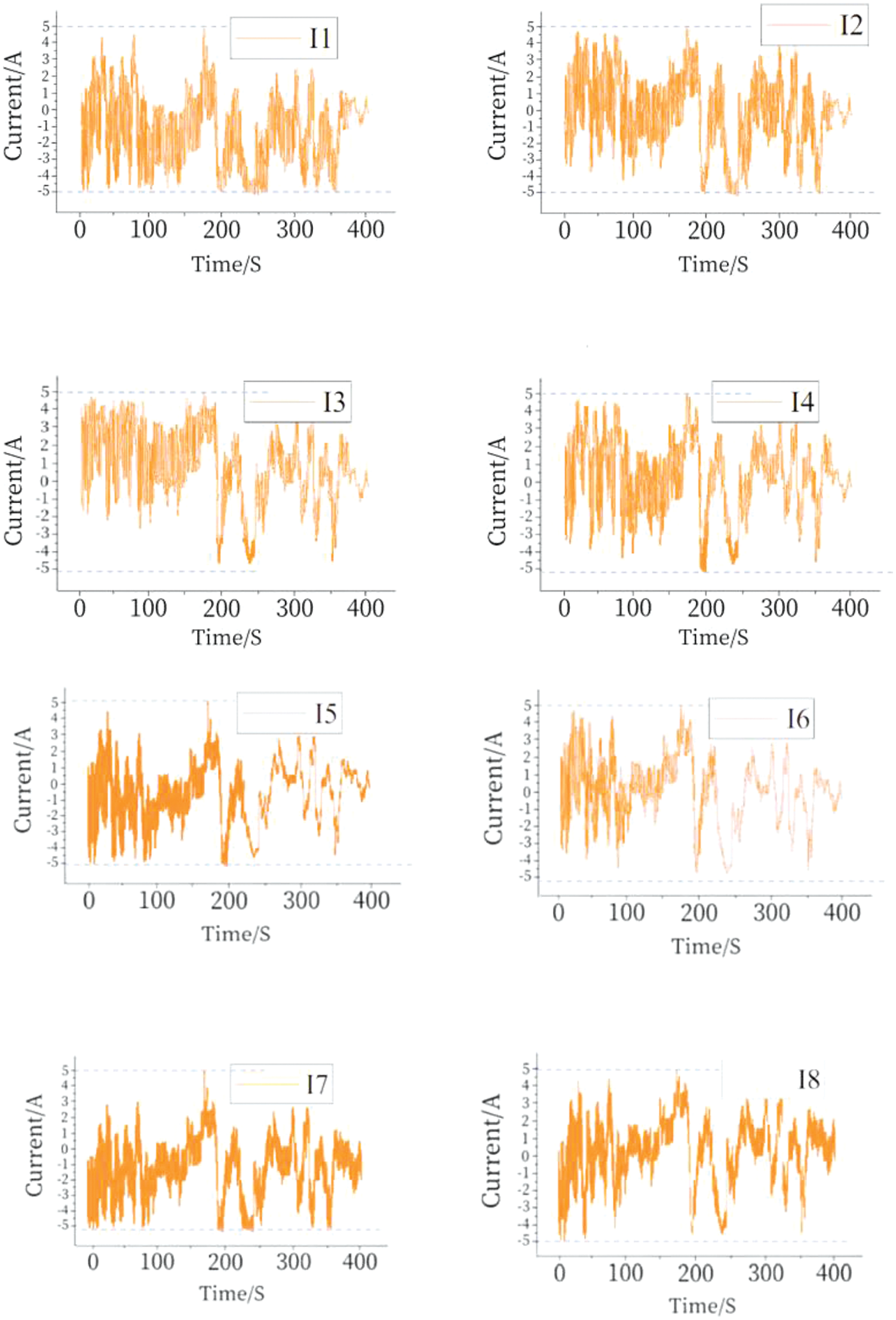
Figure 18: Fuzzy control strategy to simulate current variation
4.2.2 Static Equilibrium Experiment
In the static equilibrium experiments, the SOC variations of Li-ion batteries with multi-layer equilibrium circuits and conventional double-layer equilibrium circuits are shown in Figs. 19a and 19b below.
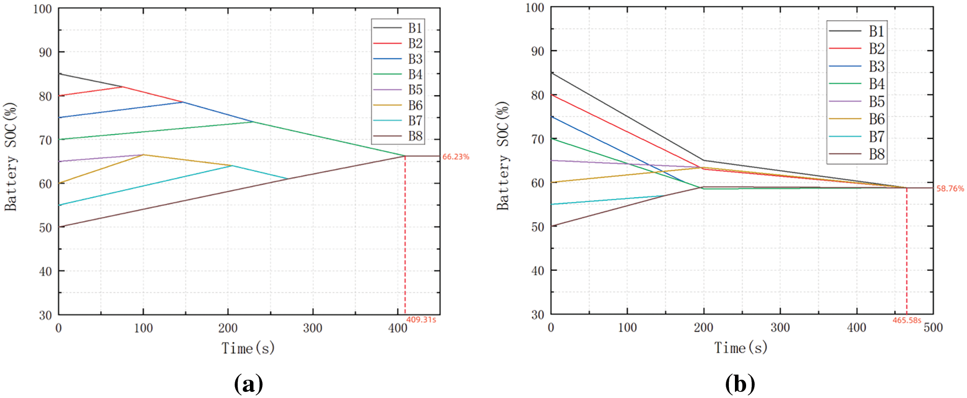
Figure 19: (a) Multilayer equilibrium circuit static equilibrium experiment. (b) Conventional double-layer equilibrium circuit static equilibrium experiment
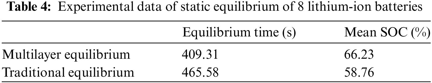
Using eight single cell lithium-ion batteries to do static equilibrium simulation experiments, the initial state, the mean value of the battery pack SOC is 67.5% when the battery pack static equilibrium is completed, the experimental data as shown in Table 4, this paper’s multilayer equilibrium circuit for equilibrium of the static equilibrium time is 409.31 s, the static equilibrium of the traditional double-layer equilibrium circuit for equilibrium of the static equilibrium time is 465.58 s, the rate of speed enhancement of 12.09%. According to the mean value of the initial SOC of each single cell and the mean value of the SOC after equilibrium, it can be concluded that the multilayer equilibrium circuit designed in this paper improves the energy transfer efficiency by 12.71% compared with the traditional equilibrium circuit.
4.2.3 Charge Equilibrium Experiment
In the charge balancing experiments, the SOC variations of Li-ion batteries with multilayer balancing circuits and conventional double-layer balancing circuits are shown in Figs. 20a and 20b below.
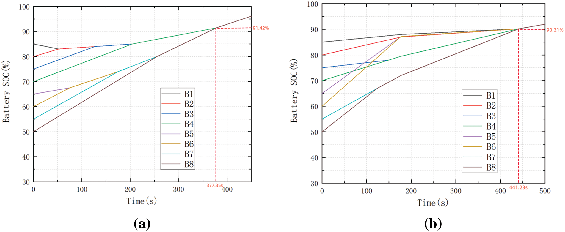
Figure 20: (a) Charge equilibrium experiment for multi-layer equilibrium circuit. (b) Charge equilibrium experiment for conventional double-level equilibrium circuit
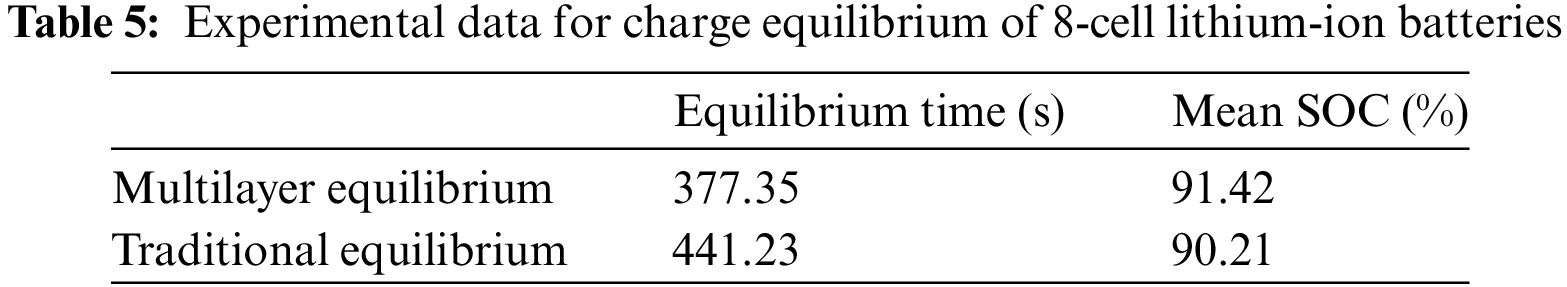
Using 8 sections of single lithium-ion batteries to do charging equilibrium simulation experiments, when the battery pack charging equilibrium is completed, the experimental data shown in Table 5, this paper’s multi-layer equilibrium circuit charging equilibrium time used for equilibrium is 377.35 s, the traditional double-layer equilibrium circuit charging equilibrium time used for equilibrium is 441.23 s, the speed of the increase of 14.48%.
4.2.4 Discharge Equilibrium Experiment
In the discharge equilibrium experiments, the SOC changes of Li-ion batteries with multilayer equilibrium circuits and conventional double-layer equilibrium circuits are shown in Figs. 21a and 21(b) below.
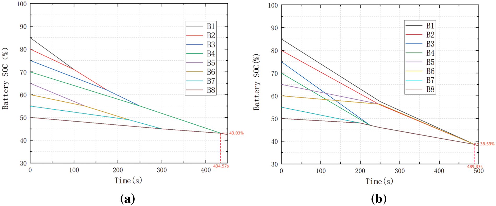
Figure 21: (a) Multilayer equilibrium circuit discharge equilibrium experiment. (b) Conventional double-layer equilibrium circuit discharge equilibrium experiment
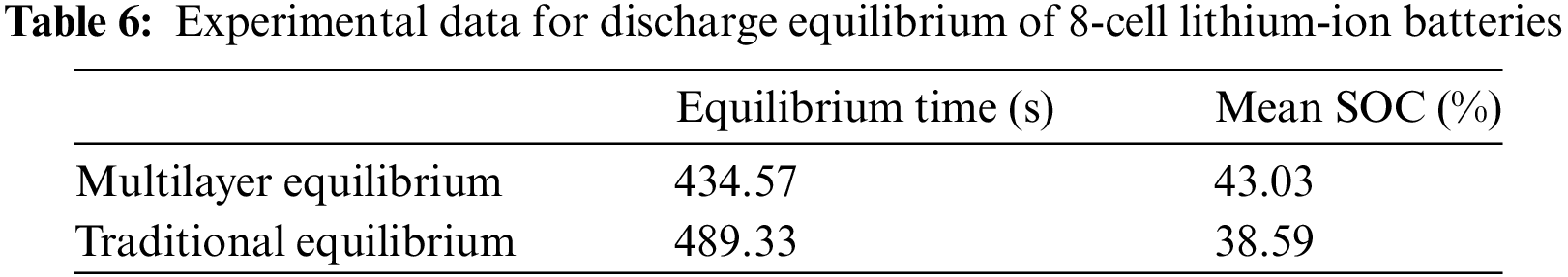
Using 8 sections of single lithium-ion battery discharge equilibrium simulation experiments, when the battery pack discharge equilibrium is completed, the experimental data shown in Table 6, this paper’s multilayer equilibrium circuit discharge equilibrium time used for equilibrium is 434.57 s, the traditional double-layer equilibrium circuit discharge equilibrium time used for equilibrium is 489.33 s, the speed of the increase of 11.19%.
In this paper, for the inconsistency of series-connected lithium-ion battery packs, a multilayer equalization method for lithium-ion batteries based on FLC is proposed, and a FLC strategy based on the SOC of batteries is proposed with the SOC as the equalization variable, which reduces the equalization time and improves the energy utilization rate. The equalization topology is divided into intra-group and inter-group. The intra-group equalization topology is the first level of equalization topology, and intra-group equalization is the first level of equalization. The inter-group equalization topology is divided into two levels, and inter-group equalization is the second level and the third level of equalization. This topology can realize the equalization between every single cell in the group, and the inter-group equalization circuit can be equalized at the same time, which can well solve the problems of slow equalization time and low efficiency of the traditional Buck-Boost topology.
In order to verify the feasibility and superiority of the FLC algorithm, a comparison experiment with the maximum equalization method is carried out. The results show that under the same equalization conditions, the FLC strategy proposed in this paper shortens the equalization time by about 3.27%, improves the energy transfer efficiency by about 66.49%, and effectively improves the consistency of the series-connected battery pack. In order to verify the feasibility and superiority of the equalization topology in this paper, comparative experiments are conducted with the traditional equalization topology under static and charge/discharge conditions. The experimental results show that compared with the traditional Buck-Boost equalization topology, the equalization topology proposed in this paper can shorten the equalization time by about 12.71%, 14.48%, and 11.19% in the static, charging, and discharging equalization experiments, respectively, which effectively improves the equalization speed of the series-connected Li-ion battery pack.
Acknowledgement: The authors acknowledge the reviewers for providing valuable comments and helpful suggestions to improve the manuscript.
Funding Statement: This research was funded by the National Natural Science Foundation of China: Research on the Energy Management Strategy of Li-Ion Battery and Sc Hybrid Energy Storage System for Electric Vehicle (51677058).
Author Contributions: The authors confirm their contribution to the paper as follows: Study conception and design: Tiezhou Wu, Yukan Zhang; data collection: Tiezhou Wu; analysis and interpretation of results: Tiezhou Wu; draft manuscript preparation: Yukan Zhang. All authors reviewed the results and approved the final version of the manuscript.
Availability of Data and Materials: Data sharing is not applicable to this article as no datasets were generated or analyzed during the current study.
Conflicts of Interest: The authors declare that they have no conflicts of interest to report regarding the present study.
References
1. Y. Hua et al., “A comprehensive review on inconsistency and equalization technology of lithium-ion battery for electric vehicles,” Int. J. Energy Res., vol. 44, no. 14, pp. 11059–11087, Nov. 2020. doi: 10.1002/er.5683. [Google Scholar] [CrossRef]
2. X. Guo, Q. Wu, C. Xing, W. Qian, and Y. Zhao, “An active equalization method for series-parallel battery pack based on an inductor,” J. Energy Storage, vol. 64, pp. 107157, Aug. 2023. doi: 10.1016/j.est.2023.107157. [Google Scholar] [CrossRef]
3. A. Samanta and S. Chowdhuri, “Active cell balancing of lithium-ion battery pack using dual DC-DC converter and auxiliary lead-acid battery,” J. Energy Storage, vol. 33, pp. 102109, Jan. 2021. doi: 10.1016/j.est.2020.102109. [Google Scholar] [CrossRef]
4. X. Liu, H. Pang, and Y. Geng, “Dual-layer inductor active equalization control for series-connected lithium-ion batteries based on SOC estimation,” Electron., vol. 11, no. 8, pp. 1169, Apr. 2022. doi: 10.3390/electronics11081169. [Google Scholar] [CrossRef]
5. Y. Chen, X. Liu, Y. Cui, J. Zou, and S. Yang, “A multi-winding transformer cell-to-cell active equalization method for lithium-ion batteries with reduced number of driving circuits,” IEEE Trans. Power Electron., vol. 31, no. 7, pp. 4916–4929, 2015. doi: 10.1109/TPEL.2015.2482500. [Google Scholar] [CrossRef]
6. M. Wang, C. Chang, and F. Ji, “A ΔSOC-based equalization strategy applied to industry,” Int. J. Low-Carbon Technol., vol. 16, no. 2, pp. 612–619, May 2021. doi: 10.1093/ijlct/ctaa095. [Google Scholar] [CrossRef]
7. X. Guo, Q. Wu, and C. Xing, “An active equalization method based on an inductor and a capacitor for series battery pack,” IEEE Trans. Power Electron, vol. 38, pp. 4040–4052, Sep. 2023. doi: 10.1109/TPEL.2022.3222333. [Google Scholar] [CrossRef]
8. B. Xia, J. Zhou, Y. Yang, H. Wang, W. Wang and Y. Lai, “A novel battery equalization method base on fuzzy logic control considering thermal effect,” IOP Conf. Ser. Earth Environ. Sci., vol. 300, no. 4, pp. 042065, Jul. 2019. doi: 10.1088/1755-1315/300/4/042065. [Google Scholar] [CrossRef]
9. B. Wang, F. Qin, X. Zhao, X. Ni, and D. Xuan, “Equalization of series connected lithium-ion batteries based on back propagation neural network and fuzzy logic control,” Int. J. Energy Res., vol. 44, no. 6, pp. 4812–4826, May 2020. doi: 10.1002/er.5274. [Google Scholar] [CrossRef]
10. T. Kim and W. Qiao, “A hybrid battery model capable of capturing dynamic circuit characteristics and nonlinear capacity effects,” IEEE Trans. Energy Convers, vol. 26, no. 4, pp. 1172–1180, Dec. 2011. doi: 10.1109/TEC.2011.2167014. [Google Scholar] [CrossRef]
11. S. Song, F. Xiao, S. Peng, C. Song, and Y. Shao, “A high-efficiency bidirectional active balance for electric vehicle battery packs based on model predictive control,” Energies, vol. 11, no. 11, pp. 3220, Nov. 2018. doi: 10.3390/en11113220. [Google Scholar] [CrossRef]
12. F. Ju, W. Deng, and J. Li, “Performance evaluation of modularized global equalization system for lithium-ion battery packs,” IEEE Trans. Autom. Sci. Eng., vol. 13, no. 2, pp. 986–996, Apr. 2016. doi: 10.1109/TASE.2015.2434052. [Google Scholar] [CrossRef]
13. M. M. Hoque, M. A. Hannan, A. Mohamed, and A. Ayob, “Battery charge equalization controller in electric vehicle applications: A review,” Renew. Sustain. Energy Rev., vol. 75, pp. 1363–1385, Aug. 2017. doi: 10.1016/j.rser.2016.11.126. [Google Scholar] [CrossRef]
14. C. Zhang, Y. Shang, Z. Li, and N. Cui, “An interleaved equalization architecture with self-learning fuzzy logic control for series-connected battery strings,” IEEE Trans. Veh. Technol., vol. 66, no. 12, pp. 10923–10934, Dec. 2017. doi: 10.1109/TVT.2017.2737401. [Google Scholar] [CrossRef]
15. J. Zheng, J. Chen, and Q. Ouyang, “Variable universe fuzzy control for battery equalization,” J. Syst. Sci. Complex., vol. 31, no. 1, pp. 325–342, Feb. 2018. doi: 10.1007/s11424-018-7366-7. [Google Scholar] [CrossRef]
16. J. Xu, B. Cao, S. Li, B. Wang, and B. Ning, “A hybrid criterion based balancing strategy for battery energy storage systems,” Energy Proc., vol. 103, pp. 225–230, Dec. 2016. doi: 10.1016/j.egypro.2016.11.277. [Google Scholar] [CrossRef]
17. Y. Zheng, W. Gao, M. Ouyang, L. Lu, L. Zhou and X. Han, “State-of-charge inconsistency estimation of lithium-ion battery pack using mean-difference model and extended Kalman filter,” J. Power Sources, vol. 383, pp. 50–58, Apr. 2018. doi: 10.1016/j.jpowsour.2018.02.058. [Google Scholar] [CrossRef]
18. T. Wu, F. Ji, L. Liao, and C. Chang, “Voltage-SOC balancing control scheme for series-connected lithium-ion battery packs,” J. Energy Storage, vol. 25, pp. 100895, Oct. 2019. doi: 10.1016/j.est.2019.100895. [Google Scholar] [CrossRef]
19. Z. Wu, R. Ling, and R. Tang, “Dynamic battery equalization with energy and time efficiency for electric vehicles,” Energy, vol. 141, pp. 937–948, Dec. 2017. doi: 10.1016/j.energy.2017.09.129. [Google Scholar] [CrossRef]
20. L. Liao and H. Chen, “Research on two-stage equalization strategy based on fuzzy logic control for lithium-ion battery packs,” J. Energy Storage, vol. 50, pp. 104321, Jun. 2022. doi: 10.1016/j.est.2022.104321. [Google Scholar] [CrossRef]
21. N. Ghaeminezhad, Q. Ouyang, X. Hu, G. Xu, and Z. Wang, “Active cell equalization topologies analysis for battery packs: A systematic review,” IEEE Trans. Power Electron., vol. 36, no. 8, pp. 9119–9135, Aug. 2021. doi: 10.1109/TPEL.2021.3052163. [Google Scholar] [CrossRef]
22. Y. Li, J. Xu, X. Mei, and J. Wang, “A unitized multi-winding transformer-based equalization method for series-connected battery strings,” IEEE Trans. Power Electron., vol. 34, no. 12, pp. 11981–11989, Dec. 2019. doi: 10.1109/TPEL.2019.2910205. [Google Scholar] [CrossRef]
23. Z. Wei, F. Peng, and H. Wang, “An LCC-based string-to-cell battery equalizer with simplified constant current control,” IEEE Trans. Power Electron., vol. 37, no. 2, pp. 1816–1827, 2021. doi: 10.1109/TPEL.2021.3102627. [Google Scholar] [CrossRef]
24. W. Han, C. Zou, L. Zhang, Q. Ouyang, and T. Wik, “Near-fastest battery balancing by cell/module reconfiguration,” IEEE Trans. Smart Grid., vol. 10, no. 6, pp. 6954–6964, Nov. 2019. doi: 10.1109/TSG.2019.2915013. [Google Scholar] [CrossRef]
25. F. Peng, H. Wang, and L. Yu, “Analysis and design considerations of efficiency enhanced hierarchical battery equalizer based on bipolar CCM buck-boost units,” IEEE Trans. Ind. Appl., vol. 55, no. 4, pp. 4053–4063, Jul. 2019. doi: 10.1109/TIA.2019.2916493. [Google Scholar] [CrossRef]
26. K. Liu, Z. Yang, X. Tang, and W. Cao, “Automotive battery equalizers based on joint switched-capacitor and buck-boost converters,” IEEE Trans. Veh. Technol., vol. 69, no. 11, pp. 12716–12724, Nov. 2020. doi: 10.1109/TVT.2020.3019347. [Google Scholar] [CrossRef]
27. S. K. Dam and V. John, “A modular fast cell-to-cell battery voltage equalizer,” IEEE Trans. Power Electron., vol. 35, no. 9, pp. 9443–9461, Sep. 2020. doi: 10.1109/TPEL.2020.2972004. [Google Scholar] [CrossRef]
28. C. H. Kuo, Y. C. Kuo, H. C. Chou, and Y. T. Lin, “P300-based brain-computer interface with latency estimation using ABC-based interval type-2 fuzzy logic system,” Int. J. Fuzzy Syst., vol. 19, no. 2, pp. 529–541, Apr. 2017. doi: 10.1007/s40815-016-0205-x. [Google Scholar] [CrossRef]
Cite This Article
 Copyright © 2024 The Author(s). Published by Tech Science Press.
This work is licensed under a Creative Commons Attribution 4.0 International License , which permits unrestricted use, distribution, and reproduction in any medium, provided the original work is properly cited.
 Downloads
 Citation Tools