
 Submit a Paper
 Propose a Special lssue
 Open Access
ARTICLE

Hybrid Multi-Infeed Interaction Factor Calculation Method Considering Voltage Regulation Control Characteristics of Voltage Source Converter
1 State Grid Smart Grid Research Institute, State Grid Corporation of China, Beijing, 102209, China
2 School of Electric Power Engineering, Northeast Electric Power University, Jilin, 132012, China
* Corresponding Author: Tuo Wang. Email:
Energy Engineering 2024, 121(8), 2257-2273. https://doi.org/10.32604/ee.2024.049861
Received 20 January 2024; Accepted 03 April 2024; Issue published 19 July 2024
 View Full Text
 Download PDF
Abstract
Voltage source converter based high voltage direct current (VSC-HVDC) can participate in voltage regulation by flexible control to help maintain the voltage stability of the power grid. In order to quantitatively evaluate its influence on the voltage interaction between VSC-HVDC and line commutated converter based high voltage direct current (LCC-HVDC), this paper proposes a hybrid multi-infeed interaction factor (HMIIF) calculation method considering the voltage regulation control characteristics of VSC-HVDC. Firstly, for a hybrid multi-infeed high voltage direct current system, an additional equivalent operating admittance matrix is constructed to characterize HVDC equipment characteristics under small disturbance. Secondly, based on the characteristic curve between the reactive power and the voltage of a certain VSC-HVDC project, the additional equivalent operating admittance of VSC-HVDC is derived. The additional equivalent operating admittance matrix calculation method is proposed. Thirdly, the equivalent bus impedance matrix is obtained by modifying the alternating current (AC) system admittance matrix with the additional equivalent operating admittance matrix. On this basis, the HMIIF calculation method based on the equivalent bus impedance ratio is proposed. Finally, the effectiveness of the proposed method is verified in a hybrid dual-infeed high voltage direct current system constructed in Power Systems Computer Aided Design (PSCAD), and the influence of voltage regulation control on HMIIF is analyzed.Keywords
The line commutated converter based high voltage direct current (LCC-HVDC) is widely used in large-capacity and long-distance transmission occasions [1,2]. Multi-infeed high voltage direct current system (MIDC) is formed by several LCC-HVDC links with close electrical distance and the receiving-end alternating current (AC) power grid. There is a strong interaction among inverters, which greatly affects the static and dynamic characteristics of the receiving-end AC power grid [3,4]. Compared with LCC-HVDC, voltage source converter based high voltage direct current (VSC-HVDC) has a more flexible control performance and can participate in voltage regulation to help to maintain the voltage stability of the power grid [5–7]. With the construction of VSC-HVDC projects, the situation gradually increases that VSC-HVDC is fed into the original MIDC system, and then a hybrid multi-infeed high voltage direct current system (HMIDC) is formed. The receiving-end power grid will show new operating characteristics due to the complex interactions among multiple inverters of different types [8–10]. The research on the interaction of multiple inverters in MIDC and HMIDC is of great significance for the planning and operation of the receiving-end power grid.
To evaluate the voltage interaction between the inverters in the MIDC, the CIGRE working group proposed the index of multi-infeed interaction factor (MIIF) [11]. MIIF is an experimental index by definition, which needs to be obtained through multiple simulations. For complex large-scale power grids, it cannot adapt to the changes in the structure and operation mode of the power grid, and it takes a lot of time for simulation. Due to the deficiencies of the simulation method, the fast calculation method of MIIF based on the impedance ratio is adopted [12–14]. The method only needs to form the AC system impedance matrix to calculate MIIF. However, the influence of the control response characteristics of LCC-HVDC is ignored in the method. Considering the control response characteristics of LCC-HVDC, the power flow equation is modified by the sensitivity of active and reactive power delivered from inverters to the bus voltage, and the calculation method of MIIF based on the Jacobian matrix is proposed [15]. Although the method has a clear physical meaning, it cannot consider the dynamic impedance characteristics of the power source, load, and other components. To take the dynamic impedance characteristics of power equipment into account, an improvement method of the equivalent impedance ratio is proposed, and the influence of the active power delivered from the inverters on the bus voltage is neglected in the method [16]. Considering the influence of active and reactive power on inverter bus voltage, the MIIF calculation method under small disturbance is proposed [17].
In the HMIDC, there are some great research efforts on the interaction of multiple inverters. The positive contribution of the VSC-HVDC link to the LCC-HVDC link in the area of commutation failure immunity index, effective short circuit ratio, voltage sensitivity factor, temporary overvoltage, and DC line fault recovery are investigated [18]. The methods of analyzing and evaluating the interaction between VSC-HVDC and LCC-HVDC control systems are proposed [19,20]. The MIIF calculation method of the HMIDC considering DC control response characteristics is proposed [21]. Few studies focus on the MIIF of the HMIDC, though it is valuable for evaluating the voltage and power stability, the risk of LCC-HVDC commutation failure, and the interaction of harmonics [22–24]. In projects, VSC-HVDC can be equipped with voltage regulation control to enhance voltage stability, which affects the voltage interaction between the inverters. It is necessary to study the MIIF calculation method in HMIDC considering the voltage regulation control characteristics of VSC-HVDC. The following two problems need to be solved:
1) How to calculate MIIF quickly and accurately in the HMIDC system.
2) How to consider the voltage regulation characteristics of VSC-HVDC during the fast calculation of MIIF.
Facing these issues, the following contributions are made:
1) Referring to the MIIF of the MIDC system, the hybrid multi-infeed interaction factor (HMIIF) of the HMIDC system is defined to describe the voltage interaction between VSC-HVDC and LCC-HVDC. The HMIIF calculation method based on the equivalent bus impedance ratio is proposed. The equivalent bus impedance matrix is obtained by modifying the AC system admittance matrix with the additional equivalent operating admittance matrix considering the characteristics of HVDC. HMIIF is calculated based on the equivalent bus impedance ratio.
2) Based on the voltage regulation control characteristic curve of a certain VSC-HVDC project, the additional equivalent operating admittance under the control of VSC-HVDC is derived to reflect the control characteristics. Under the voltage regulation control, the admittance is updated and used in the HMIIF calculation method based on the equivalent bus impedance ratio.
This paper proposes the HMIIF calculation method considering voltage regulation control characteristics of VSC-HVDC. Based on the power system network equations, the additional equivalent operating admittance matrix considering the control response characteristics of DC under small disturbance is established. According to the characteristic curve between the reactive power and the voltage of a certain VSC-HVDC project, the additional equivalent operating admittances are derived, and the additional equivalent operating admittance matrix is constructed. The AC system impedance matrix is modified by the additional equivalent operating admittance matrix, and the equivalent bus impedance matrix is obtained. The HMIIF is calculated by the equivalent bus impedance ratio. The simulation model of the hybrid dual-infeed DC system is built in PSCAD/EMTDC to verify that the calculation method can effectively obtain the index HMIIF.
In the MIDC, MIIF can be used to evaluate the voltage interaction between the inverters. Similarly, to describe the voltage interaction between the inverters in the HMIDC, the hybrid multi-feed interaction factor (HMIIF) can be introduced. HMIIFji is the ratio of the voltage changes at the inverter buses j and i in HMIDC when inverter bus i induces an approximate 1% step voltage through the artificial switched connection of a shunt reactive element.
where ∆Ui and ∆Uj are the voltage change rate of the inverter bus i and j, and Ui is the voltage of the inverter bus i before the voltage step.
Assuming a total of N inverters are connected to the receiving-end power grid, there are k LCC-HVDC links and N-k VSC-HVDC links. Based on the multi-port Thevenin equivalent method, a simplified model of the HMIDC can be established, as shown in Fig. 1. In the figure, Ei ∠ ξi and Zi are the AC equivalent source voltage and impedance of inverter i, Ki and XTi are the transformation ratio and leakage reactance of the transformer connected to inverter i, Ui ∠ θi and Bci are the equivalent admittance of bus voltage and reactive power compensation capacitor of inverter i, and Zi,j is the equivalent coupling impedance between inverter i and j.
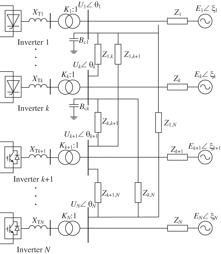
Figure 1: Simplified HMIDC system model
According to the power network equation, the bus voltage Uj of the inverter j before the voltage step can be expressed as:
where Zjm is the mutual impedance between the bus nodes of inverter j and m, and Im is the current injected into the bus node of the inverter m.
According to the definition of HMIIF, it is assumed that the shunt reactor ZLi is connected to the bus of inverter i, which induces an approximate 1% step voltage. The equivalent circuit of the system after the voltage step is shown in Fig. 2.
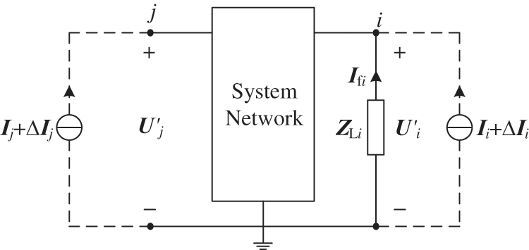
Figure 2: Equivalent circuit after voltage step
After the voltage step, the bus voltage U′j of inverter j can be written as:
where Ifi is the current flowing from the grounding point to the bus node of the inverter i through the reactor ZLi, and ∆ Im is the current variation caused by the voltage step.
The bus voltage U′i of inverter i can be expressed as:
By calculating (4), the current Ifi can be obtained as:
The voltage variation ∆ Uj can be further written as:
If rewriting (6) into the vector, the expression can be given:
where Zj0 is the row vector composed of the jth row elements of the AC system impedance matrix Z, and ∆I is the column vector of the current variation.
If rewriting (7) into the matrix, the following expression can be given:
where Z0i is a column vector composed of elements in the ith column of the AC system impedance matrix Z, and ∆U is the column vector of the voltage variation.
In the case of small disturbances, it can be considered that the power grid is linear near the steady-state operating point, and the additional equivalent operating admittance at the bus node of inverter m is defined as:
The matrix Y∆ with the additional equivalent operating admittance as the main diagonal elements can be constructed. Rewriting (9) into the matrix, the expression can be given:
By substituting (10) into (8), the column vector of the voltage variation can be deduced as:
where E0i is a column vector composed of elements in the ith column of the unit matrix E.
Assuming Zeq=( Y–Y∆)−1, (11) can be rewritten as:
Observing (12), it can be seen that under small disturbance, the voltage variation vector can be expressed as the product of the ith column vector of the equivalent bus impedance matrix and the current injected into the bus node of the inverter i by the shunt reactor ZLi.
3 Calculation of Additional Equivalent Operating Admittance
The additional equivalent operating admittance matrix is a diagonal matrix composed of additional equivalent operating admittance as its elements. The diagonal matrix elements need to be deduced.
For any inverter, the apparent power delivered by the inverter is SI = UI II*. Where UI is the bus voltage of the inverter, and II is the current flowing from the inverter to the bus. Under small disturbances, apparent power variation ∆SI satisfy can be expressed as:
Then, (13) can be written as:
According to the definition of HMIIF, the reactance of the shunt reactive element needs to be extremely large to show an approximate 1% step voltage in the bus. Before and after the voltage step, the variation of the phase angle of the bus voltage can be approximately ignored. Therefore,
Under the steady-state operation of the HMIDC, the system operating parameters can be known. If the functional relationship between the apparent power and the magnitude of bus voltage is constructed and substituted into (15), the elements of the additional equivalent operating admittance matrix Y∆ can be calculated.
3.1 Equivalent Operating Admittance of LCC-HVDC
In the LCC-HVDC link, constant DC current (CC) control is used in the rectifier, while constant extinction angle (CE) control is used in the inverter. LCC-HVDC link satisfies the following operating equation:
where UdI is the DC voltages of the inverter, PI is the active power transmitted by the inverter, QI is the reactive power delivered by the inverter, KI and XTI are the transformation ratio and leakage reactance of the transformer connected to the inverter, φI and γI are the power factor angle and extinction angle of the inverter, respectively, and Id is the DC current.
The functional relationship between the apparent power and the magnitude of the bus voltage for the LCC-HVDC link can be derived based on (16)–(20), and the additional equivalent operating admittances can be obtained [17]. Eq. (21) is the calculation equation for the additional equivalent operating admittance for the LCC-HVDC link.
The relevant parameters A is followed as:
The additional equivalent operating admittance of the LCC-HVDC can be calculated based on the above equations.
3.2 Equivalent Operating Admittance of VSC-HVDC
For the VSC-HVDC link, the rectifier or the inverter needs to adopt CV control to keep the DC voltage constant while the other can adopt CP control. VSC-HVDC can be equipped with voltage regulation control to help to maintain the voltage stability of the AC grid in projects. Since the DC link can only transmit active power, there is no need to consider the voltage regulation control of the rectifier.
For a certain VSC-HVDC project with voltage regulation control in southern China, the characteristic curve between the reactive power and the bus voltage is shown in Fig. 3. When the bus voltage of the inverter is in the range of [Ulow, Uhigh], the inverter adopts constant reactive power (CQ) control. If the voltage is located in the range of [Umin, Ulow] or [Uhigh, Umax], the voltage regulation control will be adopted. Assuming a large disturbance makes the voltage out of [Umin, Umax], the ride-through control will be started. This paper focuses on the calculation of HMIIF under the small disturbance and analyzes the CQ control and the voltage regulation control rather than the ride-through control. In the project, Qmin = −0.2 pu, Qmax = 0.2 pu, Umin = 0.9 pu, Umax = 1.1 pu, Ulow = 0.95 pu, and Uhigh = 1.05 pu.
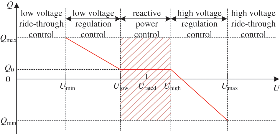
Figure 3: Characteristic curve between reactive power and bus voltage of a certain VSC-HVDC project
3.2.1 Constant Reactive Power (CQ) Control
In this control mode, the reactive power QI delivered by the inverter is constant Q0. While the rectifier adopts constant active power (CP) control and active power transmitted is PR, the inverter adopts constant DC voltage (CV) control and DC voltage is UdI. The steady-state equation of VSC-HVDC can be expressed as:
Therefore, the apparent power SI delivered by the inverter can be derived as:
From Eq. (24), it can be seen that the variation of the apparent power ∆SI = 0. Substituting the expressions of SI and ∆SI into (15), the additional equivalent operating admittance of the VSC-HVDC under the control mode can be obtained as:
While the rectifier adopts CV control, the inverter adopts CP control and the active power transmitted is PI. Similarly, the additional equivalent operating admittance of the VSC-HVDC under the control mode can be obtained as:
3.2.2 Low Voltage Regulation (LVR) Control
In this control mode, the reactive power QI delivered by the inverter can be expressed by the bus voltage UI.
where klow is the droop coefficient of the low voltage regulation control, and it can be calculated as:
While the rectifier adopts CP control and the active power transmitted is PR, the inverter adopts CV control and the DC voltage is UdI. The apparent power SI delivered by the inverter can be derived as:
From Eq. (29), the variation ∆SI of the apparent power can be deduced as:
Substituting the expressions of SI and ∆SI into (15), the additional equivalent operating admittance of the VSC-HVDC under the control mode can be obtained as:
While the rectifier adopts CV control and the DC voltage is UdR, the inverter adopts CP control and the active power is PI. Similarly, the additional equivalent operating admittance of VSC-HVDC under the control mode can be obtained as:
3.2.3 High Voltage Regulation (HVR) Control
In this control mode, the additional equivalent operating admittance of VSC-HVDC can be deduced referring to the low voltage regulation control.
While the rectifier adopts CP control and the active power is PR, the inverter adopts CV control and the DC voltage is UdI. The additional equivalent operating admittance is expressed as:
While the rectifier adopts CV control, the inverter adopts CP control and the active power is PI. The additional equivalent operating admittance is expressed as:
Observing the additional equivalent operating admittance calculation equations, it can be seen that the additional equivalent operating admittance can be obtained according to the system operating parameters. The additional equivalent operating admittance matrix Y∆ can be formed.
In the HMIDC system, the equivalent bus impedance matrix Zeq can be obtained by modifying the original AC system admittance matrix Y with the additional equivalent operating admittance matrix Y∆. According to the definition of HMIIF and (12), the calculation expression of the HMIIF between inverter j and i can be obtained as:
The complete calculation process of HMIIF is shown in Fig. 4. The proposed calculation method is an improvement of the method based on impedance ratio. The voltage regulation control characteristics of VSC-HVDC are modeled in additional equivalent operating admittance. The control response characteristics of LCC-HVDC and VSC-HVDC are shown by the additional equivalent operating admittance matrix. A more accurate calculation value of HMIIF can be obtained by modifying the impedance of the original power network. It is helpful to evaluate the voltage interaction between the inverters in the HMIDC quickly and accurately.
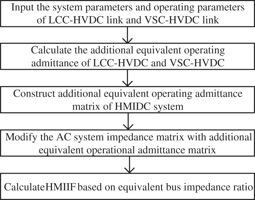
Figure 4: Complete calculation process
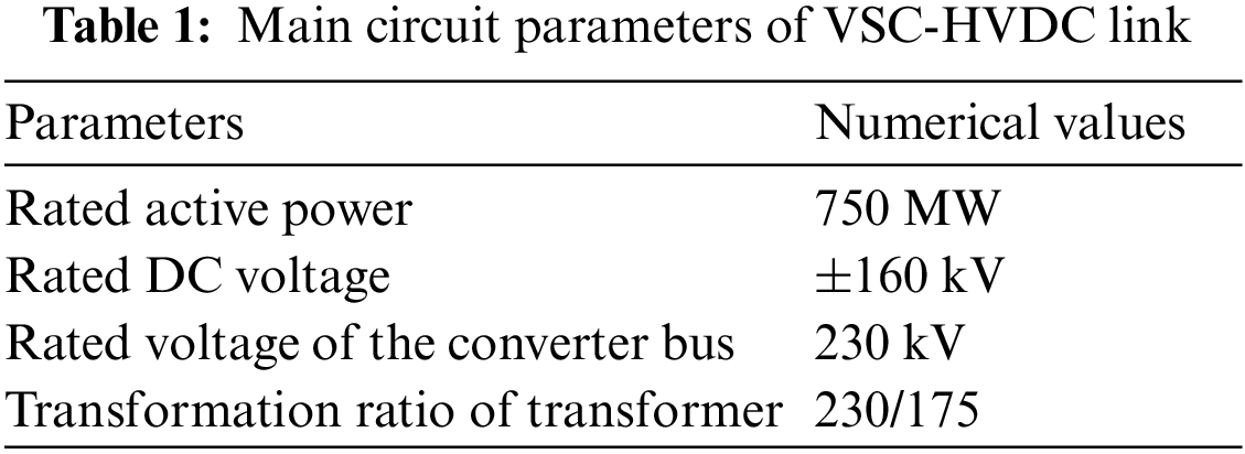
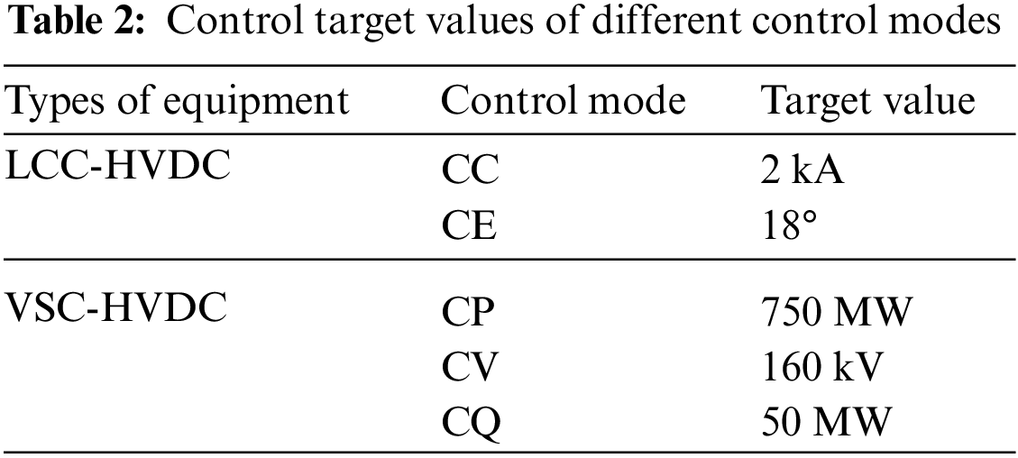
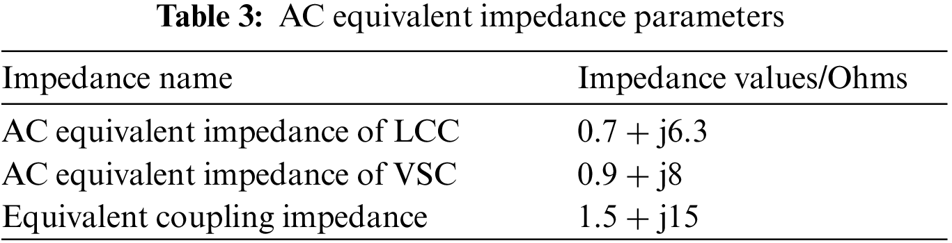
In order to verify the effectiveness of the HMIIF calculation method, a hybrid dual-infeed HVDC system is built in Power Systems Computer Aided Design (PSCAD). The system structure is shown in Fig. 5. The parameters of CIGRÉ HVDC benchmark system are adopted for LCC-HVDC. The main circuit parameters of VSC-HVDC are shown in Table 1. The inverters of LCC-HVDC and VSC-HVDC are named as inverter 1 and inverter 2, respectively, and the control target values are shown in Table 2. The AC system equivalent impedance parameters are shown in Table 3.
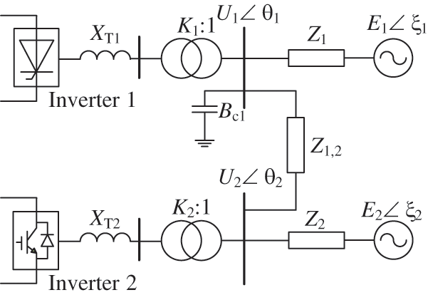
Figure 5: Hybrid dual-infeed system
At 3 s, inverter bus 1 or 2 induces an approximate 1% step voltage through the artificial switched connection of a shunt reactive element and HMIIF is calculated based on the time domain simulation method. In addition, the impedance ratio method and the proposed method are used to calculate HMIIF for comparison.
5.1 Validation of Calculation Method under CQ Control
The AC equivalent source voltage magnitudes of LCC-HVDC and VSC-HVDC are set to 1.05 and 1 pu, respectively. In this case, VSC-HVDC operates in CQ mode. The numerical comparison of different acquisition methods for HMIIF under CQ control mode is shown in Table 4. Since the calculation result deviation of different acquisition methods for HMIIF is small, only the simulation results for calculating HMIIF21 are given in Fig. 6. The predicted bus voltage of VSC-HVDC from the impedance ratio method and the proposed method is obtained based on calculated HMIIF, respectively. Similarly, only the simulation results for calculating HMIIF21 are given under the LVR control and HVR control.
Figure 6: Simulation results under CQ control
Observing the simulation results in Fig. 6, when the bus of LCC-HVDC induces an approximate 1% step voltage under CQ control, the predicted bus voltage of VSC-HVDC from the impedance ratio method and the proposed method is almost the same as the time domain simulation method.
It can be seen from Table 4 that when the VSC-HVDC adopts CQ control, the maximum calculation error of the proposed method is 3.22%, while that of the impedance ratio method is 4.44%. The proposed method considers the control response characteristics of LCC-HVDC and VSC-HVDC. Compared with the impedance ratio method, the proposed method can obtain more accurate index values.
5.2 Validation of Calculation Method under LVR Control
The AC equivalent source voltage magnitudes of LCC and VSC are set to 1.05 and 0.85 pu, respectively. In this case, VSC operates in LVR control mode and the simulation results are shown in Fig. 7. Numerical comparison of different acquisition methods for HMIIF under this control mode is shown in Table 4.

Figure 7: Simulation results under LVR control
Observing the simulation results in Fig. 7, when the bus of LCC-HVDC induces an approximate 1% step voltage under LVR control, the predicted bus voltage of VSC-HVDC from the proposed method is closer to the time domain simulation method than the impedance ratio method.
It can be found from Table 4 that the LVR control of VSC-HVDC nearly has no influence on the HMIIF12. It means that the LVR control of VSC-HVDC cannot change the effect of the voltage disturbance at the bus of VSC-HVDC on the bus voltage of LCC-HVDC. However, the HMIIF21 under the LVR control is smaller than that under CQ control. Therefore, the LVR control of VSC-HVDC can weaken the effect of the voltage disturbance at the bus of LCC-HVDC on the bus voltage of VSC-HVDC.
Additionally, Table 4 shows that the maximum calculation error of the proposed method is 3.56%, while that of the impedance ratio method is 5.07%. The proposed method considers the LVR control characteristics of VSC-HVDC. Compared with the impedance ratio method, the calculation error is smaller.
5.3 Validation of Calculation Method under HVR Control
The AC equivalent source voltage magnitudes of LCC and VSC are set to 1.05 and 1.1 pu, respectively, and the voltage phase angles are both set to 0. In this case, VSC operates in HVR control mode and the simulation results are shown in Fig. 8. Numerical comparison of different acquisition methods for HMIIF under this control mode is shown in Table 4.
Figure 8: Simulation results under HVR control
Observing the simulation results in Fig. 8, when the bus of LCC-HVDC induces an approximate 1% step voltage under HVR control, the predicted bus voltage of VSC-HVDC from the proposed method is closer to the time domain simulation method than the impedance ratio method.
From Table 4, the HVR control of VSC-HVDC cannot change the effect of the voltage disturbance at the bus of VSC-HVDC on the bus voltage of LCC-HVDC. However, the HVR control of VSC-HVDC can weaken the effect of the voltage disturbance at the bus of LCC-HVDC on the bus voltage of VSC-HVDC. It can be seen the HMIIF21 under the HVR control is smaller than that under the LVR control. The reason for the phenomenon is that there is a bigger droop coefficient in the HVR control mode.
Moreover, it can be found in Table 4 that the maximum calculation error of the proposed method is 3.81%, while that of the impedance ratio method is 5.20%. The proposed method considers voltage regulation control characteristics of VSC-HVDC. Compared with the impedance ratio method, the calculation accuracy is higher.
5.4 The Influence of Reactive Power from VSC-HVDC on HMIIF
In the HMIDC system, changing reactive power from VSC-HVDC can alter the DC additional equivalent operating admittance, thereby affecting the HMIIF index. Adjust the reactive power target value of VSC-HVDC to obtain the HMIIF as shown in Fig. 9a.
Figure 9: Influence of reactive power from VSC-HVDC and AC system impedance on HMIIF
Observing Fig. 9a, it can be seen that as the reactive power from VSC-HVDC increases, the HMIIF12 increases, indicating that the voltage disturbance of VSC-HVDC converter bus has a greater impact on the voltage of other converter buses, while the HMIIF21 decreases, indicating that the voltage disturbance of other converter buses has a smaller impact on the voltage of VSC-HVDC converter bus. Therefore, when voltage disturbances occur at the VSC-HVDC converter bus, the reactive power from VSC-HVDC should be appropriately reduced. When voltage disturbances occur at other converter buses, increasing the reactive power output of VSC-HVDC appropriately can reduce the interaction between converter bus voltages, which is beneficial for maintaining the voltage stability of other converter buses.
5.5 The Influence of AC System Equivalent Impedance on HMIIF
For a simplified model of a hybrid multi-infeed AC/DC system, the equivalent impedance of the AC system includes the equivalent source impedance and the equivalent coupling impedance, whose values directly determine the node impedance of the AC system, thereby affecting the HMIIF. By simply changing the AC equivalent impedance Z1 of LCC-HVDC, the AC equivalent impedance Z2 of VSC-HVDC, and the equivalent coupling impedance Z1, 2, the HMIIF index is shown in Fig. 9.
From Figs. 9b and 9c, it can be seen that as the AC equivalent impedance of LCC increases, HMIIF12 increases, while HMIIF21 remains almost unchanged. As the AC equivalent impedance of VSC increases, HMIIF21 increases, while HMIIF12 remains almost unchanged. Observing Fig. 9d, an increase in equivalent coupling impedance can simultaneously reduce HMIIF12 and HMIIF21 weakening the voltage interaction between the converters.
Based on the above case study, different control modes, reactive power from VSC-HVDC, and AC system equivalent impedance will affect HMIIF. The main findings are as follows:
1) The voltage regulation control of VSC-HVDC greatly affects the HMIIF21 but nearly has no influence on the HMIIF12. The voltage regulation control of VSC-HVDC can reduce the HMIIF21. It means that the voltage regulation control can weaken the effect of the voltage disturbance at the bus of LCC-HVDC on the bus voltage of VSC-HVDC, which can help to maintain the voltage stability of the power grid.
2) The increase in the reactive power from VSC-HVDC can decrease the HMIIF21. When voltage disturbances occur, increasing the reactive power from VSC-HVDC appropriately can reduce the interaction between converter bus voltages, which is beneficial for maintaining the voltage stability of other converter buses.
3) The increase in the AC equivalent impedance of LCC-HVDC can increase HMIIF12, and the increase in the AC equivalent impedance of VSC-HVDC can increase HMIIF21. Decreasing AC equivalent impedance can reduce the influence on the converter bus voltage from the voltage disturbances occurring at other converter buses. The increase in equivalent coupling impedance can simultaneously reduce HMIIF12 and HMIIF21, weakening the voltage interaction between the converters.
In this paper, a hybrid multi-infeed interaction factor calculation method considering voltage regulation control characteristics of VSC-HVDC is proposed, and a hybrid dual-infeed DC system is constructed for simulation verification and analysis. The calculation method based on the equivalent bus impedance ratio can be used to obtain HMIIF. Only relying on the operating parameters and the AC system admittance matrix, the HMIIF between inverters can be calculated at one time with fast calculation speed and high accuracy. And the HMIIF under different control modes are greatly different. It cannot be ignored the influence of the control mode while analyzing the voltage interaction between inverters. The voltage regulation control of VSC-HVDC can weaken the effect of the voltage disturbance at the bus of LCC-HVDC on the bus voltage of VSC-HVDC, which can help to maintain the voltage stability of the power grid.
Acknowledgement: The authors thank the editors and reviewers for their valuable comments and helpful suggestions to improving the manuscript.
Funding Statement: This work was supported by the Technology Project of the State Grid Corporation Headquarters Management (Contract No. 5100-202158467A-0-0-00).
Author Contributions: The authors confirm contribution to the paper as follows: Study conception and design: Tuo Wang; data collection: Fengze Han, Tuo Wang; analysis and interpretation of results: Shan Liu, Chengbin Chi, Yanan Wu, Lin Zhu; draft manuscript preparation: Fengze Han, Tuo Wang. All authors reviewed the results and approved the final version of the manuscript.
Availability of Data and Materials: All data generated or analysed during this study are included in this published article.
Conflicts of Interest: The authors declare that they have no conflicts of interest to report regarding the present study.
References
1. C. Wu, D. Zhang, and J. He, “A double-ended protection principle for an LCC-VSC-MTDC system with strong anti-interference ability,” Energy Eng., vol. 120, no. 2, pp. 299–316, Nov. 2022. doi: 10.32604/ee.2023.023532 [Google Scholar] [CrossRef]
2. D. Zhang, C. Wu, and J. He, “Single-ended protection principle for LCC-VSC-MTDC system with high resistance fault tolerance,” Energy Eng., vol. 120, no. 1, pp. 1–21, Oct. 2022. doi: 10.32604/ee.2022.023304 [Google Scholar] [CrossRef]
3. H. Xiao, X. Duan, Y. Zhang, and Y. Li, “Comparative analysis of inter-inverter interactions in emerging hierarchical-infeed and conventional multi-infeed LCC-HVDC systems,” IEEE Trans. Energy Convers., vol. 38, no. 1, pp. 27–37, Mar. 2023. doi: 10.1109/TEC.2022.3192489. [Google Scholar] [CrossRef]
4. M. Szechtman, M. J. Ximenes, and A. R. Saavedra, “Comparative analysis of stability and electromagnetic transient studies for HVDC multi-infeed systems,” CSEE J. Power Energy Syst., vol. 3, no. 3, pp. 253–259, Sep. 2017. doi: 10.17775/CSEEJPES.2016.01730. [Google Scholar] [CrossRef]
5. R. Shah, J. C. Sánchez, R. Preece, and M. Barnes, “Stability and control of mixed AC-DC systems with VSC-HVDC: A review,” IET Gener. Transmiss. Distrib., vol. 12, no. 10, pp. 2207–2219, Apr. 2018. doi: 10.1049/iet-gtd.2017.1140. [Google Scholar] [CrossRef]
6. I. E. Maysse et al., “Nonlinear observer-based controller design for VSC-based HVDC transmission systems under uncertainties,” IEEE Access, vol. 11, pp. 124014–124030, Nov. 2023. doi: 10.1109/ACCESS.2023.3330440. [Google Scholar] [CrossRef]
7. I. E. Maysse et al., “Observer and nonlinear control design of VSC-HVDC transmission system,” Int. J. Electr. Power Energy Syst., vol. 145, pp. 108609, Feb. 2023. doi: 10.1016/j.ijepes.2022.108609. [Google Scholar] [CrossRef]
8. D. Oliveira, G. C. B. Leal, D. Herrera, E. Galván-Díez, J. M. Carrasco and M. Aredes, “An analysis on the VSC-HVDC contribution for the static voltage stability margin and effective short circuit ratio enhancement in hybrid multi-infeed HVDC systems,” Energies, vol. 16, no. 1, pp. 532, doi: 10.3390/en16010532. [Google Scholar] [CrossRef]
9. H. Xiao and Y. Li, “Multi-infeed voltage interaction factor: A unified measure of inter-inverter interactions in hybrid multi-infeed HVDC systems,” IEEE Trans. Power Del., vol. 35, no. 4, pp. 2040–2048, Dec. 2019. doi: 10.1109/TPWRD.2019.2960393. [Google Scholar] [CrossRef]
10. H. H. Yin et al., “Interaction mechanism analysis and additional damping control for hybrid multi-infeed HVDC system,” IEEE Trans. Power Del., vol. 37, no. 5, pp. 3904–3916, Oct. 2022. doi: 10.1109/TPWRD.2022.3140826. [Google Scholar] [CrossRef]
11. CIGRE Working Group B4.41, “Systems with multiple DC infeed,” Technical Brochure 364, Paris, France: CIGRE, 2008, pp. 16–19. [Google Scholar]
12. Y. Shao and Y. Tang, “Fast evaluation of commutation failure risk in multi-infeed HVDC systems,” IEEE Trans. Power Syst., vol. 33, no. 1, pp. 646–653, May 2017. doi: 10.1109/TPWRS.2017.2700045. [Google Scholar] [CrossRef]
13. H. Xiao, H. Li, A. M. Gole, and X. Duan, “Computationally efficient and accurate approach for commutation failure risk areas identification in multi-infeed LCC-HVdc systems,” IEEE Trans. Power Electron, vol. 35, no. 5, pp. 5238–5253, Sep. 2019. doi: 10.1109/TPEL.2019.2943182. [Google Scholar] [CrossRef]
14. X. Chen, A. M. Gole, and M. Han, “Analysis of mixed inverter/rectifier multi-infeed HVDC systems,” IEEE Tran. Power Del., vol. 27, no. 3, pp. 1565–1573, Mar. 2012. doi: 10.1109/TPWRD.2012.2187356. [Google Scholar] [CrossRef]
15. D. L. H. Aik and G. Andersson, “Analysis of voltage and power interactions in multi-infeed HVDC systems,” IEEE Trans. Power Del., vol. 28, no. 2, pp. 816–824, Jan. 2013. doi: 10.1109/TPWRD.2012.2227510. [Google Scholar] [CrossRef]
16. C. Xia, X. Hua, Z. Wang, and Z. Huang, “Analytical calculation for multi-infeed interaction factors considering control modes of high voltage direct current links,” Energies, vol. 11, no. 6, pp. 1506, doi: 10.3390/en11061506. [Google Scholar] [CrossRef]
17. F. Zhang et al., “Study on calculation method of multi-infeed HVDC interaction factor considering small disturbance response characteristics of HVDC transmission system,” (in ChineseProc. CSEE, vol. 39, no. 18, pp. 5308–5315, Sep. 2019. [Google Scholar]
18. Q. Guo, M. Yoon, C. Kim, and G. Jang, “Commutation failure and voltage sensitivity analysis in a hybrid multi-infeed HVDC system containing modular multilevel converter,” Int. Trans. Elect. Energy Syst., vol. 26, no. 10, pp. 2259–2271, Oct. 2016. doi: 10.1002/etep.2206. [Google Scholar] [CrossRef]
19. C. Guo, W. Liu, C. Zhao, and X. Ni, “Small-signal dynamics and control parameters optimization of hybrid multi-infeed HVDC system,” Int. J. Electr. Power Energy Syst., vol. 98, pp. 409–418, Jun. 2018. doi: 10.1016/j.ijepes.2017.12.009. [Google Scholar] [CrossRef]
20. C. Guo, W. Liu, J. Zhao, and C. Zhao, “Impact of control system on small-signal stability of hybrid multi-infeed HVDC system,” IET Gener. Transmiss. Distrib., vol. 12, no. 19, pp. 4233–4239, Oct. 2018. doi: 10.1049/iet-gtd.2018.5087. [Google Scholar] [CrossRef]
21. Q. Li, T. Wang, C. Mao, Z. Li, Y. Xin and S. Jiang, “Multi-infeed interaction factor calculation method of hybrid multi-infeed HVDC system considering DC control characteristics,” (in ChinesePower Syst. Tech., vol. 45, no. 8, pp. 3125–3133, Aug. 2021. [Google Scholar]
22. D. Liu, D. Shi, and Y. Li, “A new definition of short-circuit ratio for multi-converter HVDC systems,” J. Electr. Eng. Tech., vol. 10, no. 5, pp. 1958–1968, Sep. 2015. doi: 10.5370/JEET.2015.10.5.1958. [Google Scholar] [CrossRef]
23. B. Rehman, C. Liu, H. Li, C. Fu, and W. Wei, “Analysis on local and concurrent commutation failure of multi-infeed HVDC considering inter-converter interaction,” J. Modern Power Syst. Clean Energy, vol. 10, no. 4, pp. 1050–1059, Jun. 2021. doi: 10.35833/MPCE.2020.000164. [Google Scholar] [CrossRef]
24. W. Yao, L. Wang, H. Zhou, Y. Xiong, and J. Wen, “Harmonics interaction mechanism and impact on extinction angles in multi-infeed HVDC systems,” IEEE Trans. Power Del, vol. 38, no. 4, pp. 2427–2440, Feb. 2023. doi: 10.1109/TPWRD.2023.3243412. [Google Scholar] [CrossRef]
Cite This Article
 Copyright © 2024 The Author(s). Published by Tech Science Press.
This work is licensed under a Creative Commons Attribution 4.0 International License , which permits unrestricted use, distribution, and reproduction in any medium, provided the original work is properly cited.
 Downloads
 Citation Tools