
 Submit a Paper
 Propose a Special lssue
 Open Access
ARTICLE

Ladder Time Stepwise Inertia Coordinated Control Method of Multiple Wind Farms to Suppress System Frequency Secondary Drop
1 Tongliao PowerSupply Company, State Grid East Inner Mongolia Electric Power Company, Tongliao, 028000, China
2 Key Laboratory of Modern Power System Simulation and Control & Renewable Energy Technology, Northeast Electric Power University, Jilin, 132012, China
* Corresponding Author: Xianchao Liu. Email:
(This article belongs to the Special Issue: Wind Energy Development and Utilization)
Energy Engineering 2024, 121(8), 2293-2311. https://doi.org/10.32604/ee.2024.048752
Received 17 December 2023; Accepted 16 April 2024; Issue published 19 July 2024
 View Full Text
 Download PDF
Abstract
When employing stepwise inertial control (SIC), wind power generation can offer significant frequency support to the power system, concurrently mitigating energy shortages and suppressing secondary frequency drop. Nonetheless, further investigation is imperative for implementing stepped inertia control due to variations in frequency regulation capabilities and operational safety among diverse wind farm groups. Consequently, this paper advocates a multi-wind farm ladder timing SIC method designed to alleviate secondary drops in system frequency. Initially, the paper introduces the fundamental principles of stepped inertia control for a doubly-fed induction generator (DFIG) and deduces the relationship between support energy, wind power deficit at the exit, and SIC’s inertia power and support duration. Subsequently, the wind farm group is categorized into three groups using the classic wind speed zoning method, and the additional power reference for SIC is computed based on rotor safety requirements. A ladder time for the wind farm groups is introduced to address the potential exacerbation of secondary frequency drop issues resulting from the simultaneous activation of stepwise inertia control across all wind farms. The relationship between the initial kinetic energy loss of the wind farm group, the power deficit upon the exit of stepwise inertia control, and the ladder time is deduced. The NSGA-II multi-objective optimization algorithm is then employed to adjust the ladder time among multiple wind farm groups in the system. Finally, a modified IEEE-9 test system comprising three wind fields is constructed in MATLAB/Simulink to validate the proposed method. The results demonstrate the efficacy of the ladder time SIC coordinated strategy in providing robust frequency support, suppressing secondary frequency drops, streamlining control tasks, and enhancing the safety of wind power frequency regulation.Keywords
In the global low-carbon transformation context, wind power generation technology has become many countries’ most competitive renewable energy generation technology [1–3]. Wind power technology has the advantages of low power generation cost and mature technology. However, as the penetration rate of doubly-fed induction generators (DFIGs) gradually increases, DFIGs operate in the maximum power tracking mode, and the rotation speed is decoupled from the power system’s frequency, making the unit unresponsive to the power grid. With the frequency fluctuation ability, the system’s frequency stability is facing severe challenges [4,5].
To ensure the secure and stable operation of the power system, numerous countries have issued guidelines for wind power auxiliary service functions, mandating that wind farms possess the same capacity to engage in system frequency regulation as traditional power plants [6,7]. Experts and scholars have proposed various frequency stability control strategies, notably reserve control of variable speed/pitch angle [8,9] and virtual inertia control [10]. The reserve control approach, relying on variable speed/pitch angle, implements active load shedding preemptively, endowing the new energy unit with swift frequency regulation reserves. In instances of grid frequency reduction, wind turbine units can release reserve power to partake actively in rapid frequency regulation. However, the frequency modulation technique of renewable energy power reserves faces limitations imposed not only by natural conditions but also by the increased fatigue load due to load-shedding operations on wind power. This operational strain leads to a shortened service life for new energy and diminished economic viability [11]. Virtual inertia control simulates the inertia response and primary frequency regulation process by detecting frequency deviation through the differential and proportional links. It utilizes the rotor to absorb or release kinetic energy, adjusting the output to achieve frequency adjustment. Despite providing the capacity to respond to frequency changes actively, the excessive use of rotor kinetic energy in comprehensive inertia control can result in a secondary drop upon exiting frequency regulation.
There are two primary approaches to addressing the issue of secondary frequency drop. One method involves enhancing the energy recovery path post-frequency regulation exit. For instance, literature [12–14] utilized torque-limited straight lines or smooth curves to govern the recovery trajectory of the wind power rotor speed. However, this method exhibits a prolonged speed recovery time, and in the event of wind speed disturbances, the operating trajectory is susceptible to deviating from the predetermined state. In another study, reference [15] devised a wind turbine timing exit strategy at the new energy station level to mitigate secondary drops. This approach relies on a time-based energy recovery method, but intricate design complexities may hinder its practical application. The second approach entails formulating a comprehensive frequency regulation “energy throughput” process for new energy. References [16–18] devised a frequency regulation path under stepwise inertial control (SIC). They constrained the tuning of frequency regulation exit time and power increment based on the frequency nadir, showcasing the substantial potential for future applications. Adjusting the frequency modulation exit time and power increment holds significant potential for future applications. However, these studies exclusively consider SIC at the wind turbine level. Given the frequency control requirements of a high-penetration renewable energy power system, it becomes imperative to account for operational disparities and safety considerations among wind farm groups. Consequently, a coordinated control strategy must be designed to suppress initial and secondary frequency drops effectively. Moreover, existing SIC variable parameter tuning methods are numerous and intricate [19,20], posing challenges in applying differentiated online applications to large-scale wind farm groups and presenting significant hurdles to further engineering applicability.
In conclusion, the current SIC frequency control strategy inadequately considers variations among wind farm groups, diminishing its practicality in power systems characterized by high wind power. This paper introduces a collaborative frequency control strategy for wind farm groups based on ladder time stepwise inertia, aiming to mitigate the initial and secondary frequency drops in the power grid while accounting for differences in wind power operation and operational safety. The main contributions compared to existing research results are the following:
(1) A fixed inertia duration is devised to enhance the applicability of the SIC strategy for wind power involvement in power system frequency regulation. This aims to alleviate control complexities and to improve feasibility in practical power grid applications.
(2) Considering the safety limit of wind power speed, the additional power command of SIC is tailored for various wind speed operation conditions. This design aims to prevent the overuse of wind power, which could result in excessively low wind power speeds and necessitate withdrawal from operation.
(3) Simultaneously initiating SIC in all wind farms may exacerbate the issue of secondary frequency drop, and the concept of ladder time for SIC among wind farm groups is introduced. The relationship between the initial kinetic energy loss of the wind farm group, power deficit upon SIC exit, and ladder time is derived, and a multi-objective optimization model is formulated. The NSGA-II multi-objective optimization algorithm is utilized to refine the ladder time coordination among multiple wind farm groups in the system.
The subsequent sections of this paper are organized as follows: Section 2 delineates the fundamental operational principles of the wind power SIC strategy and scrutinizes the primary reasons for the secondary drop in frequency. Section 3 formulates the ladder time SIC strategy, encompassing SIC duration, additional power command, and ladder time. Section 4 substantiates the efficacy of the proposed control strategy through experimentation in a 9-node example featuring a group of wind farms.
2 Stepwise Inertia Control of DFIG
Doubly-fed induction generators (DFIG) primarily consist of wind turbines, gearboxes, high and low-speed shafts, asynchronous generators, back-to-back converters, and their respective control systems. The power system configuration featuring DFIG is illustrated in Fig. 1.
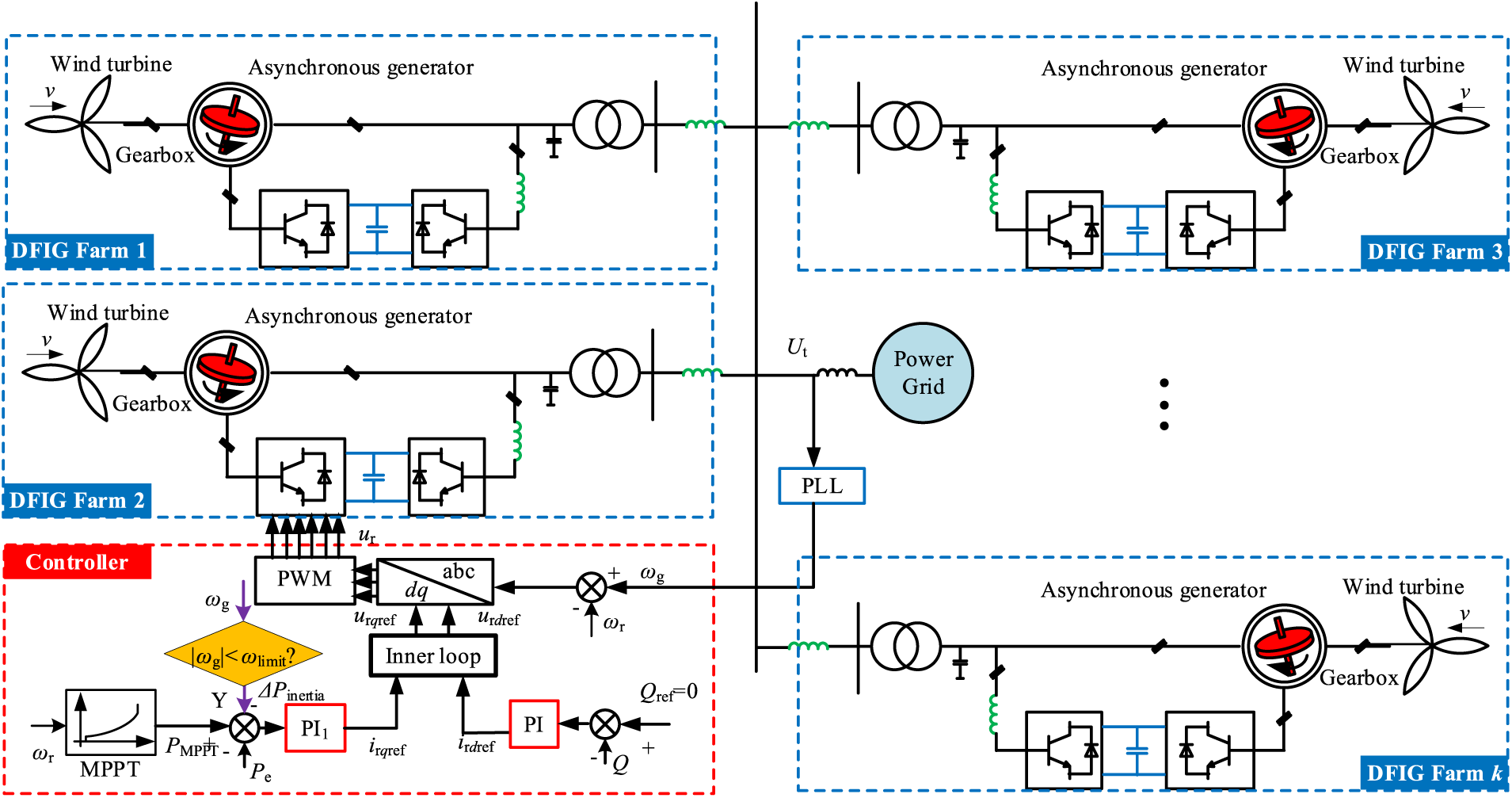
Figure 1: DFIG grid-connected system structure
The DFIG regulates the rotor current via the rotor-side converter to ensure its electromagnetic power operates at the maximum power tracking point. Consequently, DFIG exhibits minimal responsiveness to the grid frequency. The mechanical torque of the DFIG can be computed using the aerodynamic equation described by the wind turbine:
When the frequency falls beyond the dead band, the SIC is activated, and the motion trajectory of the DFIG is shown in Fig. 2.
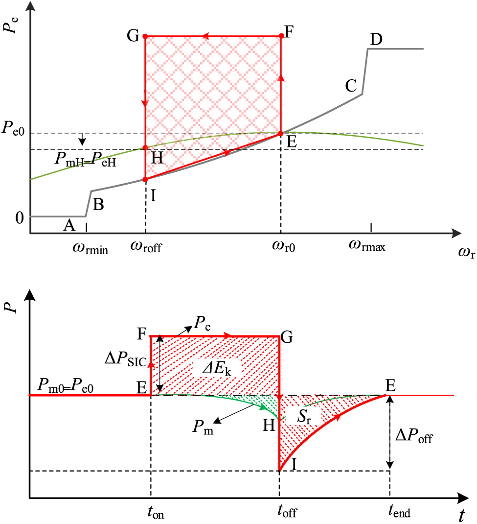
Figure 2: Active power curve of DFIG under SIC
In Fig. 2, ABCD represents the maximum power point tracking (MPPT) curve of DFIG. The initial operating point of DFIG is denoted as point E. When a sudden change in frequency occurs in the power grid due to a disturbance (taking the frequency drop caused by a sudden load increase as an example), the stepwise inertia control generates an additional active power reference
where
At the toff moment, SIC exits the run. The MPPT control of DFIG is in the dominant position, the electromagnetic power suddenly changes to
where
According to Eq. (3), it can be analyzed that there is a nonlinear relationship between the power plunge
where
The couplings Eqs. (3)–(5) then give
From Eq. (6), it can be seen that there is a positive correlation between the plunging power
As the DFIG operates at point I, where the electromagnetic power is less than the mechanical power, the grid frequency change rate transitions from negative to positive. The additional torque becomes negative, initiating acceleration of the DFIG rotor. Concurrently, under the control of MPPT and extra torque, the electromagnetic power swiftly recovers, and the mechanical power gradually returns to
From the whole process of SIC, the kinetic energy released by the rotor of the wind turbine can be deduced as:
where
If a linear approximation describes the speed recovery phase, the energy change in the recovery phase is known to be according to the principle of conservation of energy:
Associative Eqs. (6) and (8) can be calculated tend as:
From Eq. (9), the stopping time mainly has an influence relationship with SIC duration and DFIG rotor inertia.
In real power grids with large-scale DFIGs, employing differentiated parameter selection raises control complexity and costs while diminishing service life. Conversely, the analysis of energy changes has hitherto focused solely on the unit level, neglecting the broader energy impact associated with the differentiated operation of large-scale wind farm groups and the potential increased risk of secondary frequency drops. Consequently, this paper aims to develop a control strategy that considers control difficulty, the frequency modulation capability of the wind farm group, and the mitigation of secondary frequency drops.
3 Ladder Stepwise Control Strategy Considering the Differentiation of DFIG Farm Group Operations
The wide-area control strategy for DFIG field groups encompasses wind turbines with small capacity and large size. Hence, it is imperative to consider variations in frequency regulation capabilities and control workload. Additionally, accounting for frequency fluctuations arising from the simultaneous frequency regulation of multiple wind farms within the actual power grid becomes crucial to address the secondary drop issue. Consequently, a stepwise control strategy is devised, considering the differentiated operation of DFIG field groups.
3.1 Stepwise Control Parameter Tuning for DFIG Farms Frequency Control Capacity and Difficulty
The SIC time of wind power is fixed (
Assume a set of wind farms
Combined with the operating conditions of the wind speed field group, the SIC power command is:
In addition, the SIC power of the wind farm group needs to meet its capacity constraints:
where
By combining Eqs. (11) and (12), the additional power for the three types of wind farm groups can be determined. For ease of control at the power grid centralized control layer, fixing the control parameters for the unified wind speed zone is convenient. Consequently, conservative initial values of 7, 10, and 12 m/s can be utilized for low, medium, and high wind speed field groups, and calculations can be performed accordingly. Taking the DFIG dynamic simulation model parameters of MATLAB/Simulink as an example, the binary table illustrating SIC power instructions for wind power speed safety constraints is presented in Table 1.
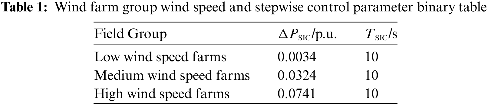
It can be seen from Table 1 that under the same frequency support time, the higher the initial wind speed, the greater the SIC additional power command designed considering speed safety and frequency support capabilities, and the greater the support energy for the power grid. The total released rotor kinetic energy of all wind farms is:
Eq. (13) indicates that, in a specific operating mode, the enhanced SIC of the wind farm group described in this article releases rotor kinetic energy to a certain extent. The challenge is to organize the rational release of rotor kinetic energy for all three types of wind farms, ensuring frequency stability in support of the grid. Simultaneously, restoring the system to its initial state in an organized and safe manner is crucial, with the primary control objective of minimizing secondary frequency drops during recovery.
3.2 DFIG Farms Step Time Interval to Suppress Frequency Secondary Drop
The primary cause of the secondary drop in system frequency is the early-stage release of rotor kinetic energy by the wind power SIC. During the rotor speed recovery stage, the system must absorb the deficient energy. From the Eq. (13) analysis, it becomes evident that the overdraft power amount
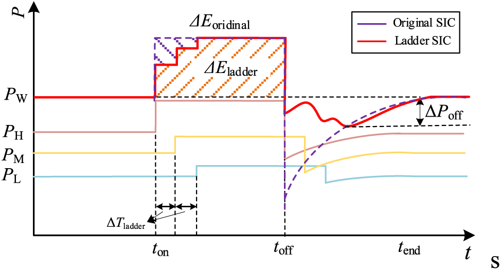
Figure 3: Active power of DFIG using ladder time SIC
In Fig. 3, the purple curve represents the active power of the wind farm group controlled by traditional SIC. In contrast, the red curve represents the active power of the wind farm group controlled by the proposed ladder SIC strategy. Observing Fig. 3, it is evident that the proposed ladder time SIC strategy diminishes the rotor speed acceleration region compared to the traditional SIC strategy. The rotor energy difference between the two can be expressed as:
Even though the energy of inertial support may experience a reduction, the energy difference can prove advantageous in addressing the overall power deficit of the wind farm group upon exiting frequency regulation. This enables a gradual recovery of the wind farm group, alleviating short-term energy gaps and mitigating the secondary frequency drop. It is worth noting that the secondary drop of the system is directly related to the ladder time. The moment of maximum power gap corresponds to the exit moment of the low wind speed field group. During this moment, the power gaps for the three echelon field groups are:
where
At this time,
3.3 SIC Ladder Time Tuning of DFIG Farms
(1) Multi-objective optimization method for ladder time tuning
This paper formulates the objective function to minimize the kinetic energy loss
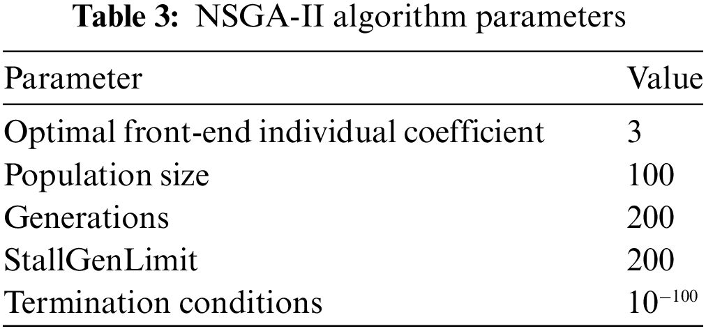
The optimization objectives aim to maximize the suppression of frequency drop and minimize wind power shortage upon exiting frequency regulation. The maximum ladder time limit is set to ensure the initial frequency modulation support effect with traditional kinetic energy. The commonly used NSGA-II multi-objective optimization algorithm is employed to solve the above model and obtain the decision variable ladder time for optimization. It is emphasized that if all wind speeds in the system are uniform, all wind farm groups can be divided into three equal parts and optimized according to the three echelon categories mentioned above.
(2) NSGA-II-based multi-objective optimization solution method
The NSGA-II (Non-dominated Sorting Genetic Algorithm II) represents an advanced genetic algorithm rooted in the principles of Pareto optimality. It improves upon the selection and reproduction methods inherent in genetic algorithms. This algorithm categorizes individuals based on their dominance and non-dominance relationships. It employs a swift, non-dominated sorting technique and measures crowding distance to identify solutions along the Pareto front. Incorporating elitism ensures a competitive environment between parent and offspring populations, thereby ensuring highly satisfactory outcomes in multi-objective optimization [21]. The schematic representation of NSGA-II’s program structure is illustrated in Fig. 4.
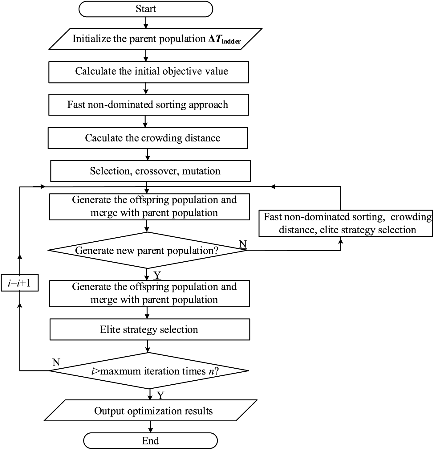
Figure 4: NSGA-II algorithm solution flow
The diagram illustrates that NSGA-II can be primarily delineated into the following key components:
a. Fast, non-dominated sorting approach
To categorize the given initial population
b. Crowding distance calculation
The calculation of crowding distance requires ascending sorting of the population based on the magnitude of each objective function value. Subsequently, for each objective function, the boundary solution (corresponding to the maximum or minimum value of the function) is assigned an infinite distance value. All other intermediate solutions are assigned a distance value equal to the absolute normalized difference in function values between two adjacent solutions. This computation is then performed for different objective functions. The crowding distance value is the sum of distances corresponding to each objective. Before calculating the crowding distance, normalize each objective function. The algorithm outlined below provides an overview of the crowding distance calculation process for all non-dominated solutions.
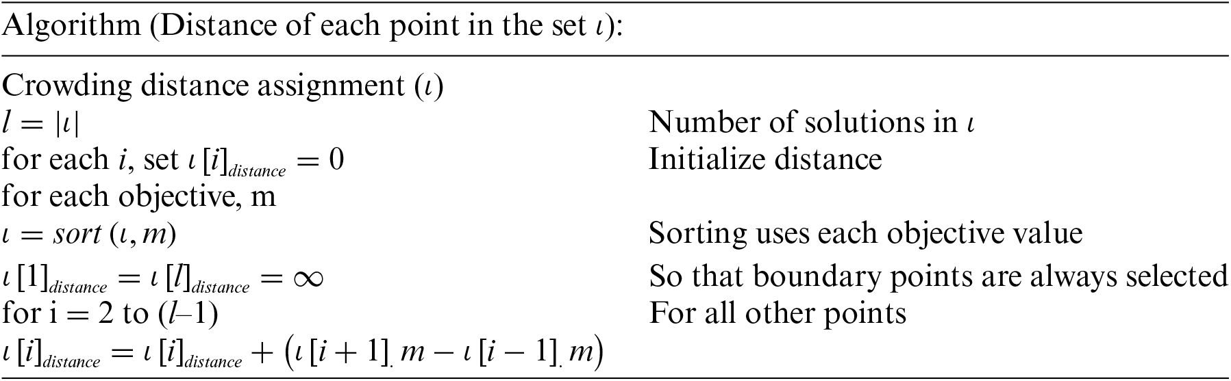
Here, ι[i].m refers to the m-th objective function value of the i-th individual in the set ι.
c. Selection operator
Two sets of individuals are randomly chosen; if the two individuals do not share the same rank, the set with the smaller crowding distance is retained. When they belong to the same rank, the set with the more considerable crowding distance is selected.
d. Elite strategy
The primary objective of the elite retention strategy is to prevent the loss of elite solutions. To achieve this, parent and new-generation solutions are blended, and a new set of solutions is subsequently generated using a fast, non-dominated method and crowding distance calculation.
In practical applications, batches of wind farm groups and ladder times can be updated on a rolling basis by the scheduling time scale, such as every 15 min—the online control framework of the proposed echelon SIC is depicted in Fig. 5.
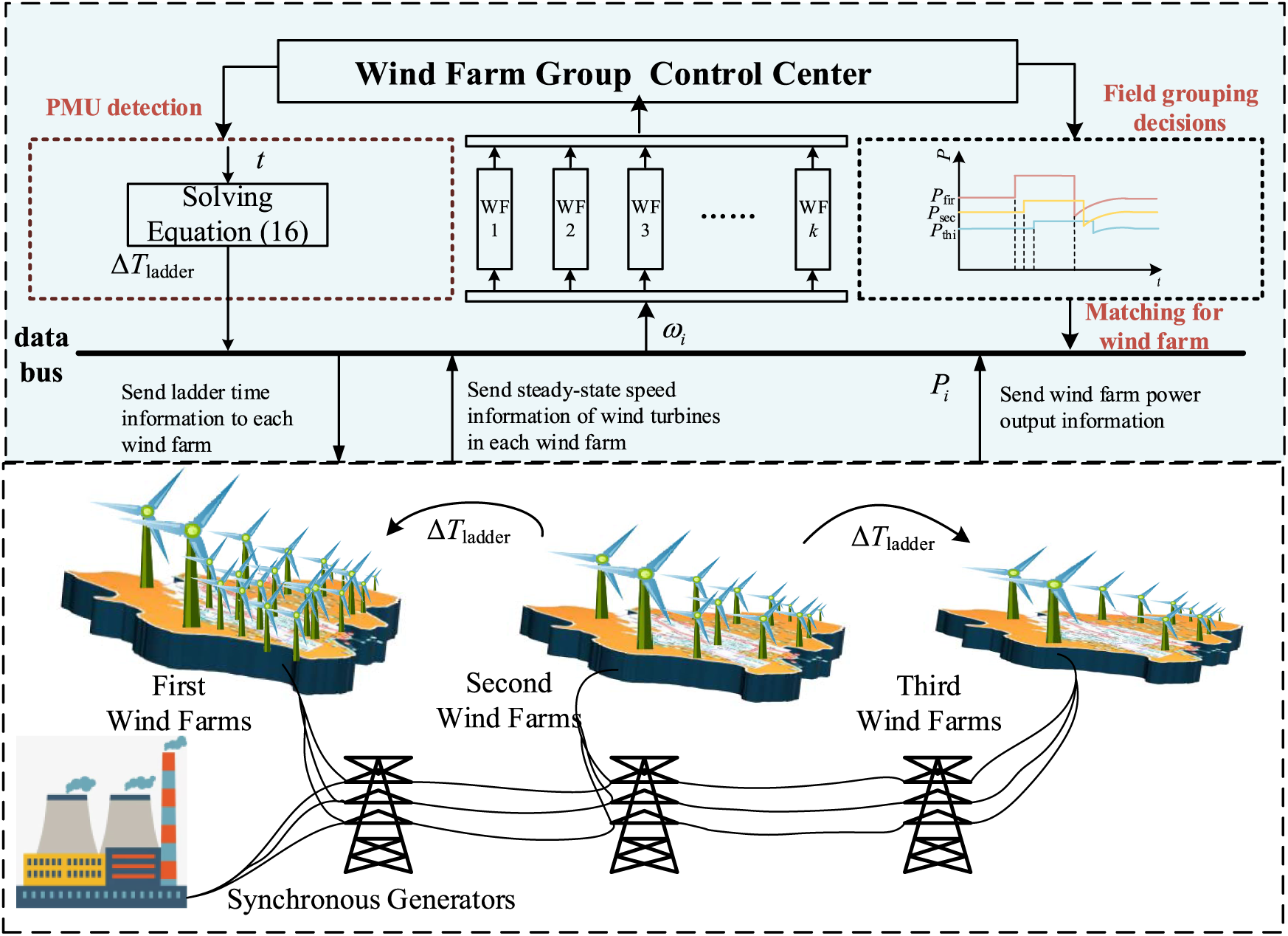
Figure 5: Ladder time SIC control frame for DFIG field groups
A WECC-9 node power system simulation model is constructed using MATLAB/Simulink to validate the efficacy of the proposed ladder time SIC coordination for wind farm groups. The system structure is illustrated in Fig. 6. Notably, three equivalent wind farms substitute generator 3. While the structural parameters of all wind turbines are identical, the number of units and wind speeds differ among the four wind farms. The critical information is summarized in Table 2.
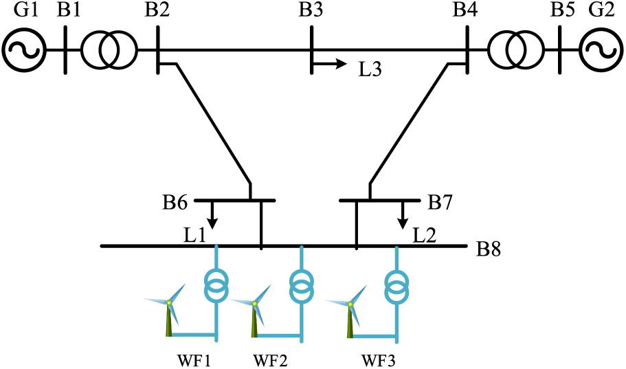
Figure 6: WECC-9 test system with wind farms
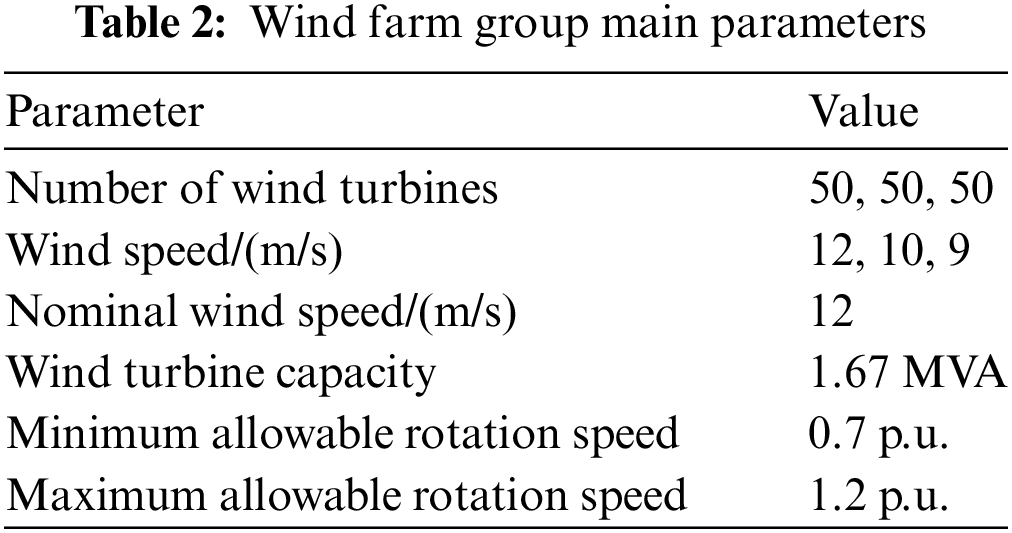
Based on the operational information provided in Table 2, the wind farms can be classified into the high wind speed group (Wind Farm 1), medium-speed group (Wind Farm 2), and low wind speed group (Wind Farm 3).
4.1 Parameter Tuning Method Verification
The ladder time SIC parameters are computed based on the wind speed, and the corresponding parameters are detailed in Table 1. The effectiveness of the proposed parameter design is verified below. Assuming the system baseline capacity is 100 MVA, the maximum
The Pareto front results are calculated using the operating information of all wind farms in the system and formula (16), as illustrated in Fig. 7.
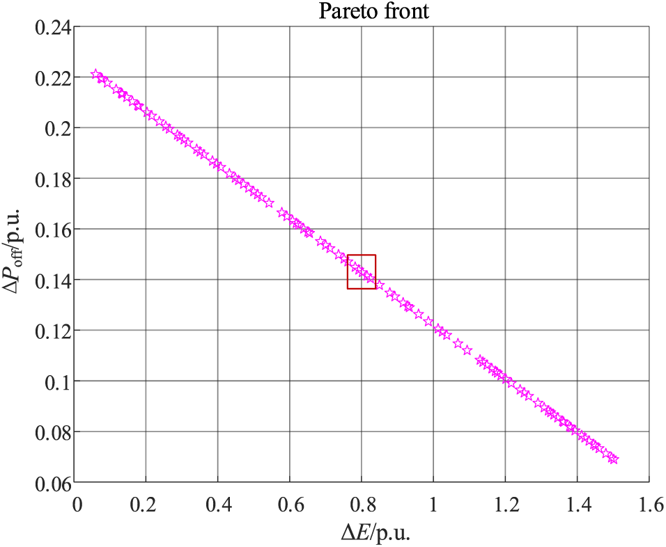
Figure 7: Multi-objective optimization results
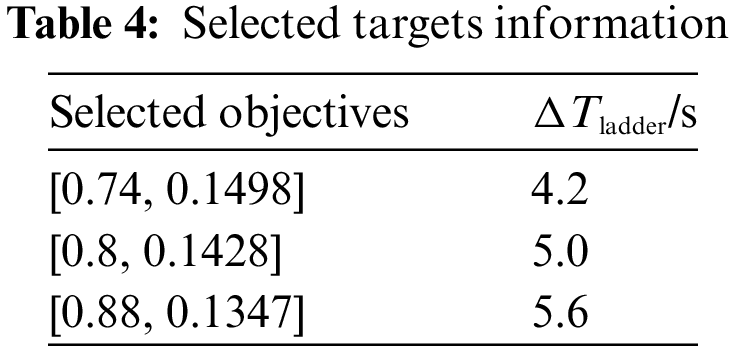
Fig. 7 displays the results of multi-objective optimization based on energy deviation and wind power shortage in the initial stage. In these optimization solution sets, both can be comprehensively considered by assigning penalty factors. However, the two physical quantities possess distinct properties. Therefore, to further select a suitable target, we suggest considering three groups that encompass all three targets: [0.74, 0.1498], [0.8, 0.1428], and [0.88, 0.1347]. Further domain simulation can be performed to obtain appropriate targets. The optimization results under the three penalty factors are detailed in Table 4.
A 5% load surge occurs at
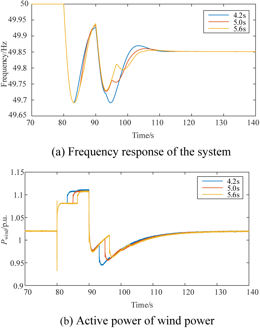
Figure 8: Multi-objective optimization results
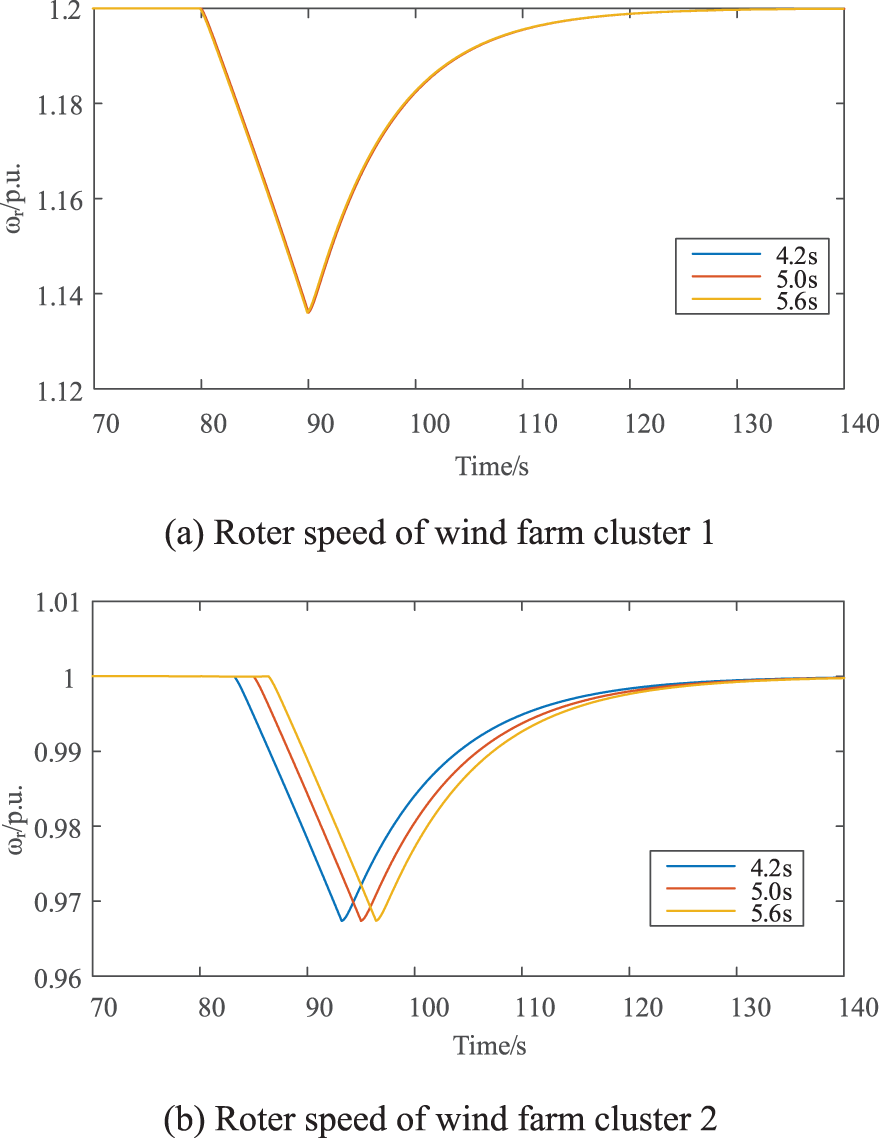
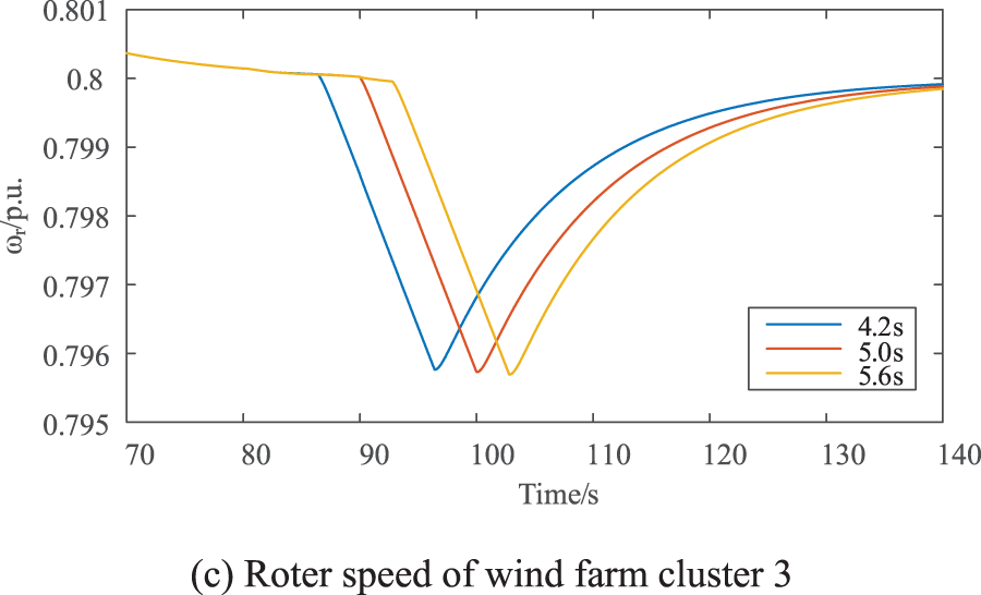
Figure 9: Variation of rotational speeds of system wind farm clusters
Fig. 8 compares frequency response with total wind power using the selected time intervals. An appropriately increased ladder time alleviates multiple frequency drops to varying degrees. A ladder time of 4.2 s may exacerbate subsequent drops more than the initial one. Simultaneously, the smaller the ladder time, the faster the frequency recovery, with less impact on the initial frequency drop. This is attributed to the system’s inertia level being approximately 4.2 s, and the second input batch has already surpassed the first frequency drop. In conclusion, considering both factors, we opt for 5 s as the basis for subsequent verification. Meanwhile, Fig. 9 depicts the dynamic response of the wind turbine speed under three distinct ladder time parameters. It is evident that, under the three proposed parameters, the minimum wind power speed remains above the predetermined minimum allowable speed (
4.2 Validation of the Proposed Ladder SIC
In the following, the effectiveness of the proposed control method is verified against the additional frequency control and conventional SIC control, respectively. Therefore, three simulation scenarios are set up as follows:
Case 1: Wind power does not participate in the frequency support control of the system.
Case 2: All wind farm groups adopt traditional SIC.
Case 3: All wind farm groups adopt the ladder time SIC.
Additionally, introduce a sudden 5% increase in active power load at
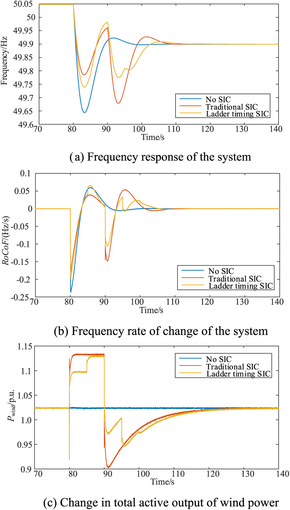
Figure 10: Comparison of simulation results under three control strategies
Figs. 10a–10c illustrate the changes in system frequency response, system frequency change rate, and total active power for the wind farm group in the three cases. In cases where wind power does not participate in the active frequency support of the system, the system experiences a single frequency drop, reaching an extreme value of 49.62 Hz, with the maximum frequency change rate reaching 0.248 Hz/s. When traditional SIC controls wind power, the first frequency drop reaches an extreme value of 49.78 Hz, and the maximum frequency change rate is 0.18 Hz/s, significantly impeding the system’s frequency change and contributing to frequency support. However, a secondary drop in frequency begins to emerge, reaching 49.65 Hz, exceeding the initial drop. After adopting the ladder time SIC strategy proposed in this paper, the first and second frequency drops are significantly suppressed, and the frequency and wind power recovery speeds are faster. To quantify the advantages of the ladder time SIC strategy, the maximum frequency change rate, the extreme value of the first frequency drop, the extreme value of the second frequency drop, and the frequency recovery time are selected as consideration factors. The relevant information is presented in Table 5.
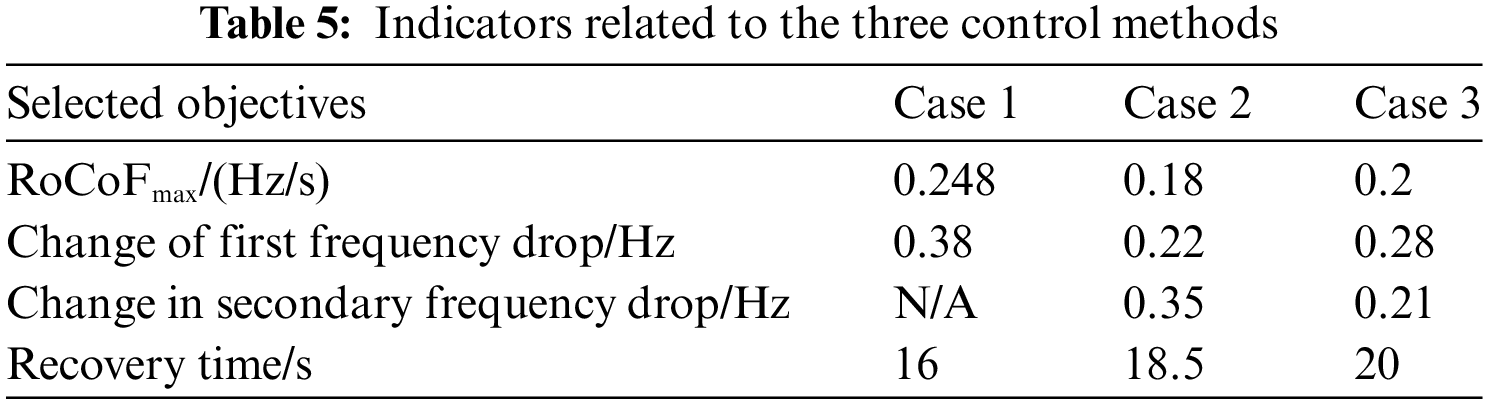
As evident from Table 5, the proposed control strategy effectively mitigates the impact of the initial frequency drop, addresses the secondary frequency drop, and facilitates faster frequency recovery. This ensures system frequency stability throughout the entire stage. To further address the speed safety issue of wind power, the results of wind power speed changes under the three cases are presented in Fig. 11.
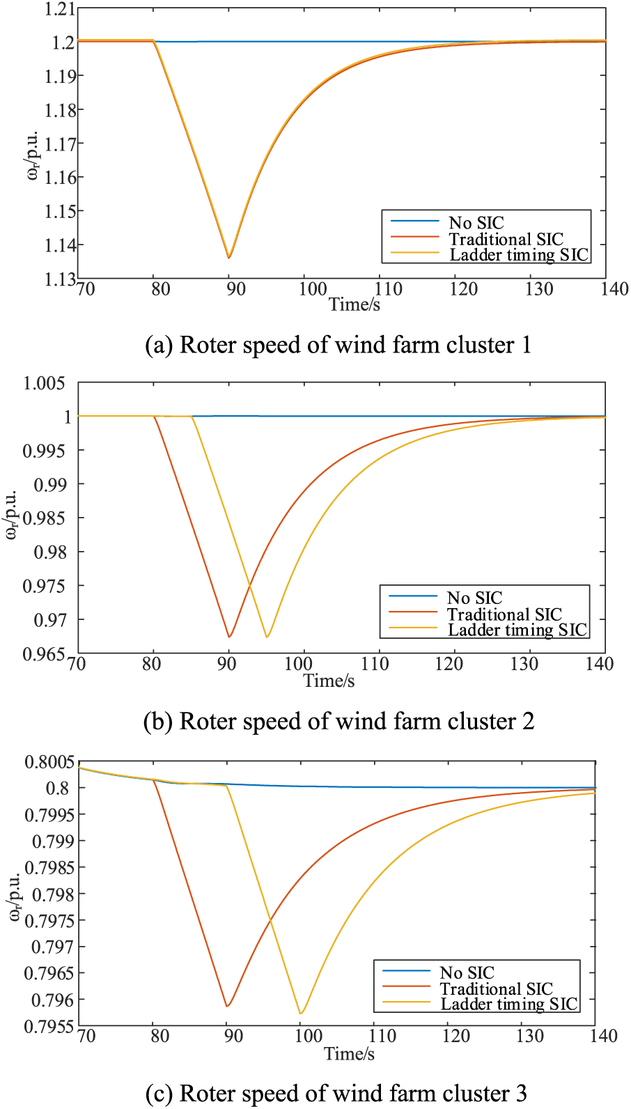
Figure 11: Variation of rotational speeds of system wind farm clusters
Figs. 11a–11c depict the rotor speed changes of wind farm groups 1–3, respectively. The rotor releases kinetic energy since the three wind farms operate in high, medium, and low wind speed states. It then gradually returns to normal following the SIC method mentioned above—a process involving kinetic energy absorption. Throughout this change process, the rotor speed consistently surpasses the safety limit, highlighting that the proposed SIC parameter tuning method considers the rotor speed’s safety during the change process and is highly feasible.
To significantly enhance the active participation of wind power in the frequency support of the power grid, this paper has introduced a ladder time SIC strategy, considering the safety of wind power speed and the supportive impact on both primary and secondary frequency drops. The effectiveness of the proposed control strategy was validated in the modified WECC-9 test system incorporating wind power, leading to the following conclusions:
(1) The paper analyzed the characteristics of wind power SIC participating in frequency regulation, establishing relationships among power deficit, SIC support time, frequency regulation full-stage time, and SIC support amount.
(2) A differentiated sequential SIC support method for multiple wind farm groups was designed, considering wind power and energy deficits. The paper established a ladder time parameter optimization and setting method for multi-wind farm groups, demonstrating the effectiveness of the proposed setting method in addressing these two factors.
(3) The proposed ladder time SIC strategy not only significantly suppresses the frequency dropout process but also mitigates the occurrence of secondary frequency dropout. Additionally, it helps avoid the risk of wind power withdrawal that may arise from excessive rotor speed overdraft.
Acknowledgement: None.
Funding Statement: This paper was supported by a grant from the fund: State Grid Inner Mongolia East Power Co., Ltd. Science and Technology Project (SGMDTL00YWJS2200994).
Author Contributions: The authors confirm contribution to the paper as follows: study conception and design: Xianchao Liu, Yuchen Qiu; data collection: He Li; analysis and interpretation of results: Jidong Li; draft manuscript preparation: Yuchen Qiu. All authors re viewed the results and approved the final version of the manuscript.
Availability of Data and Materials: The authors confirm that the data supporting the findings of this study are available within the article.
Conflicts of Interest: The authors declare that they have no conflicts of interest to report regarding the present study.
References
1. Ratnam, K. S., Palanisamy, K., Yang, G. (2020). Future low-inertia power systems: Requirements, issues, and solutions–A review. Renewable and Sustainable Energy Reviews, 124, 109773. 10.1016/j.rser.2020.109773 [Google Scholar] [CrossRef]
2. Kushwaha, P., Prakash, V., Bhakar, R., Yaragatti, U. R. (2022). Synthetic inertia and frequency support assessment from renewable plants in low carbon grids. Electric Power Systems Research, 209, 107977. 10.1016/j.epsr.2022.107977 [Google Scholar] [CrossRef]
3. Wu, M., Shi, J., Wen, H., Qiu, Y., Guo, C. (2022). Research on power and energy balance of new power system under low carbon emission path. Energy Reports, 8, 197–207. 10.1016/j.egyr.2022.10.133 [Google Scholar] [CrossRef]
4. Yan, K., Li, G., Zhang, R., Xu, Y., Jiang, T. et al. (2023). Frequency control and optimal operation of low-inertia power systems with HVDC and renewable energy: A review. IEEE Transactions on Power Systems, 39(2), 1–17. [Google Scholar]
5. Wu, Z., Gao, W., Gao, T., Yan, W., Zhang, H. et al. (2018). State-of-the-art review on frequency response of wind power plants in power systems. Journal of Modern Power Systems and Clean Energy, 6(1), 1–16. 10.1007/s40565-017-0315-y [Google Scholar] [CrossRef]
6. Karbouj, H., Rather, Z. H., Flynn, D., Qazi, H. W. (2019). Non-synchronous fast frequency reserves in renewable energy integrated power systems: A critical review. International Journal of Electrical Power & Energy Systems, 106, 488–501. 10.1016/j.ijepes.2018.09.046 [Google Scholar] [CrossRef]
7. Obaid, Z. A., Cipcigan, L. M., Abrahim, L., Muhssin, M. T. (2019). Frequency control of future power systems: Reviewing and evaluating challenges and new control methods. Journal of Modern Power Systems and Clean Energy, 7(1), 9–25. 10.1007/s40565-018-0441-1 [Google Scholar] [CrossRef]
8. Prasad, R., Padhy, N. P. (2020). Synergistic frequency regulation control mechanism for DFIG wind turbines with optimal pitch dynamics. IEEE Transactions on Power Systems, 35(4), 3181–3191. 10.1109/TPWRS.59 [Google Scholar] [CrossRef]
9. Morren, J., Pierik, J., de Haan, S. W. (2006). Inertial response of variable speed wind turbines. Electric Power Systems Research, 76(11), 980–987. 10.1016/j.epsr.2005.12.002 [Google Scholar] [CrossRef]
10. Berizzi, A., Bosisio, A., Ilea, V., Marchesini, D., Perini, R. et al. (2022). Analysis of synthetic inertia strategies from wind turbines for large system stability. IEEE Transactions on Industry Applications, 58(3), 3184–3192. 10.1109/TIA.2022.3154671 [Google Scholar] [CrossRef]
11. Wang, Y., Bayem, H., Giralt-Devant, M., Silva, V., Guillaud, X. et al. (2014). Methods for assessing available wind primary power reserve. IEEE Transactions on Sustainable Energy, 6(1), 272–280. [Google Scholar]
12. Kang, M., Kim, K., Muljadi, E., Park, J. W., Kang, Y. C. (2016). Frequency control support of a doubly-fed induction generator based on the torque limit. IEEE Transactions on Power Systems, 31(6), 4575–4583. 10.1109/TPWRS.2015.2514240 [Google Scholar] [CrossRef]
13. Wu, Z., Gao, W., Wang, X., Kang, M., Hwang, M. et al. (2016). Improved inertial control for permanent magnet synchronous generator wind turbine generators. IET Renewable Power Generation, 10(9), 1366–1373. 10.1049/rpg2.v10.9 [Google Scholar] [CrossRef]
14. Nie, Y., Liu, J., Gao, L., Wu, Y., Li, Z. (2023). Nonlinear rotor kinetic energy control strategy of DFIG-based wind turbine participating in grid frequency regulation. Electric Power Systems Research, 223, 109678. 10.1016/j.epsr.2023.109678 [Google Scholar] [CrossRef]
15. Conroy, J. F., Watson, R. (2008). Frequency response capability of full converter wind turbine generators in comparison to conventional generation. IEEE Transactions on Power Systems, 23(2), 649–656. 10.1109/TPWRS.2008.920197 [Google Scholar] [CrossRef]
16. Kang, M., Lee, J., Hur, K., Park, S. H., Choy, Y. et al. (2015). Stepwise inertial control of a doubly-fed induction generator to prevent a second frequency dip. Journal of Electrical Engineering & Technology, 10(6), 2221–2227. 10.5370/JEET.2015.10.6.2221 [Google Scholar] [CrossRef]
17. Bao, W., Ding, L., Liu, Z., Zhu, G., Kheshti, M. et al. (2020). Analytically derived fixed termination time for stepwise inertial control of wind turbines–Part I: Analytical derivation. International Journal of Electrical Power & Energy Systems, 121, 1–10. [Google Scholar]
18. Guo, Y., Bao, W., Ding, L., Liu, Z., Kheshti, M. et al. (2020). Analytically derived fixed termination time for stepwise inertial control of wind turbines—Part II: Application strategy. International Journal of Electrical Power & Energy Systems, 121, 106106. [Google Scholar]
19. Tan, B., Zhao, J., Netto, M., Krishnan, V., Terzija, V. et al. (2022). Power system inertia estimation: Review of methods and the impacts of converter-interfaced generations. International Journal of Electrical Power & Energy Systems, 134, 107362. 10.1016/j.ijepes.2021.107362 [Google Scholar] [CrossRef]
20. Skiparev, V., Nosrati, K., Tepljakov, A., Petlenkov, E., Levron, Y. et al. (2023). Virtual inertia control of isolated microgrids using an NN-based VFOPID controller. IEEE Transactions on Sustainable Energy, 14(3), 1558–1568. 10.1109/TSTE.2023.3237922 [Google Scholar] [CrossRef]
21. Seshadri, A. (2006). A fast elitist multiobjective genetic algorithm: NSGA-II. MATLAB Central, 182, 182–197. [Google Scholar]
Cite This Article
 Copyright © 2024 The Author(s). Published by Tech Science Press.
This work is licensed under a Creative Commons Attribution 4.0 International License , which permits unrestricted use, distribution, and reproduction in any medium, provided the original work is properly cited.
 Downloads
 Citation Tools