
 Submit a Paper
 Propose a Special lssue
 Open Access
ARTICLE

Performance of Gas-Steam Combined Cycle Cogeneration Units Influenced by Heating Network Terminal Steam Parameters
1 Zhongshan Jiaming Electric Power Co., Ltd., CNOOC Gas & Power Group, Zhongshan, 528403, China
2 School of Electric Power, South China University of Technology, Guangzhou, 510640, China
* Corresponding Author: Cheng Yang. Email:
Energy Engineering 2024, 121(6), 1495-1519. https://doi.org/10.32604/ee.2024.047832
Received 19 November 2023; Accepted 02 February 2024; Issue published 21 May 2024
 View Full Text
 Download PDF
Abstract
The determination of source-side extracted heating parameters is of great significance to the economic operation of cogeneration systems. This paper investigated the coupling performance of a cogeneration heating and power system multidimensionally based on the operating characteristics of the cogeneration units, the hydraulic and thermodynamic characteristics of the heating network, and the energy loads. Taking a steam network supported by a gas-steam combined cycle cogeneration system as the research case, the interaction effect among the source-side prime movers, the heating networks, and the terminal demand thermal parameters were investigated based on the designed values, the plant testing data, and the validated simulation. The operating maps of the gas-steam combined cycle cogeneration units were obtained using THERMOFLEX, and the minimum source-side steam parameters of the steam network were solved using an inverse solution procedure based on the hydro-thermodynamic coupling model. The cogeneration operating maps indicate that the available operating domain considerably narrows with the rise of the extraction steam pressure and flow rate. The heating network inverse solution demonstrates that the source-side steam pressure and temperature can be optimized from the originally designed 1.11 MPa and 238.8°C to 1.074 MPa and 191.15°C, respectively. Under the operating strategy with the minimum source-side heating parameters, the power peak regulation depth remarkably increases to 18.30% whereas the comprehensive thermal efficiency decreases. The operation under the minimum source-side heating steam parameters can be superior to the originally designed one in the economy at a higher price of the heating steam. At a fuel price of $0.38/kg and the power to fuel price of 0.18 kg/(kW·h), the critical price ratio of heating steam to fuel is 119.1 kg/t. The influence of the power-fuel price ratio on the economic deviation appears relatively weak.Keywords
Nomenclature
| Unit price ($) | |
| Power peak regulation depth | |
| Diameter of steam pipeline (m) | |
| Specific enthalpy of steam at node center (J/kg) | |
| Acceleration of gravity (m/s2) | |
| Depth of pipe buried directly (m) | |
| Coefficient of convective heat transfer (W/(m2·K)) | |
| Total heat transfer coefficient (W/(m2·K)) | |
| Axial length of pipeline (m) | |
| Fuel mass flow rate (kg/s) | |
| The steam flow at jth iteration (t/h) | |
| Heating steam flow (t/h) | |
| Average electric power supply (MW) | |
| Steam pressure (MPa) | |
| Heat transfer resistance ((m·K)/W) | |
| Relative humidity | |
| Temperature (K) | |
| Temperature (°C) | |
| Flow velocity (m/s) | |
| Ratio of energy price to fuel price (kg/(kW·h)) | |
| Coefficient of volume expansion (K-1) | |
| Ratio of heating steam price to fuel price (kg/t) | |
| The temperature difference between the outermost of the pipe and the ambient (K) | |
| Efficiency (%) | |
| Fuel output-cost ratio | |
| Thermal conductivity (W/(m·K)) | |
| Thermal conductivity of the fluid surrounding the pipeline (W/(m·K)) | |
| Soil thermal conductivity (W/(m·K)) | |
| Steam dynamic viscosity (pa·s) | |
| Kinematic viscosity of steam (m2/s) | |
| Angle between the pipe section and horizontal direction (°) | |
| Density (kg/m3) | |
| Acronyms | |
| CHP | Cogeneration of heating and power |
| HP | High-pressure |
| IP | Intermediate-pressure |
| LP | Low-pressure |
| HRSG | Heat recovery steam generator |
| TCA | Turbine rotor cooling air system |
| FGH | Fuel gas heating |
| LHV | Lower heating value |
| Re | The number of Reynolds |
| Pr | The steam Prandtl criterion number |
| Gr | The Graschof criterion number |
| Sub and Superscripts | |
| cc | Combined cycle cogeneration unit |
| h | Average heating supply |
| f | Fuel |
| chp | Cogeneration of heating and power |
| p | Power or energy |
| s | Steam |
| 0 | Parameters at design condition |
| a | Ambient |
| i | In the pipeline |
| e | Outside of the steam pipeline |
The district and centralized heating systems have become an effective measure for low-carbon and circular development, efficient utilization of energy, and as well, for high-quality economic and social development [1]. According to the National Bureau of Statistics 2021 from China, the central heating steam capacity reached 11.8 × 10⁴ t/h, with a heating capacity of 6.8 × 10⁹ GJ by the end of December 2021. In the medium and long term, during the 14th Five-Year Plan period, the district heating capacity and total heat supply will maintain a steady growth trend. Cogeneration of heating and power (CHP) is the main type of source for district or central heating, owing to its cascade utilization of energy and high efficiency [2,3]. The heating source can be produced by many prime movers including coal-fired steam power units [4], gas turbines, and combined cycle units [5–7], etc. The steam for heating may be extracted from the turbine interstage or exhaust, which will influence the power output of the units. Thus, the source-side parameters of the steam or water for heating are important for CHP unit economic operation [8,9].
The source-side steam parameters, i.e., mass flow, pressure, and temperature, depend on the characteristics of prime movers and the demand-side heating load [10]. Rich researches have been carried out on the optimization of CHP design capacity and operating strategies. An optimum design of a CHP system was achieved by using a combination of pinch technology and mathematical programming, where the system consisted of a gas turbine as the topping cycle, a hot oil system, and an organic Rankine cycle as the bottoming cycle [11]. To recover the excessive waste heat from the exhaust steam and reduce the exergy destruction of the heating supply, Pang et al. proposed a steam-ejected CHP system and carried out research on the comparative designs and optimizations of the steam ejector [12]. To reduce the energy losses in economic, energy, and environmental terms of view, a method was established by optimizing the nominal capacities of the components in a trigeneration system for a watersport complex [13].
Concerning performance improvement of CHP systems, Zhang et al. [14] investigated the configuration of enamel heat pipe exchange (EHPE) in a CHP system. Their result indicated that the application of EHPE could obviously improve the energy efficiency and slightly promote the exergy efficiency. In order to improve the operating flexibility of CHP units influenced by the strong interdependency of heating and power cogeneration, Yu et al. [15] proposed demand-side thermal storage in a regional integrated energy system. Liu et al. [16] proposed a method to express the feasible operation domain of a coal-fired double-extraction CHP unit with a 3D operation domain, and the operating boundary constraints of the double-extraction unit were elaborated. The optimal scheme of heating modes was obtained under different power loads. A source-network-load-storage scheduling scheme considering thermal inertia was proposed to realize the coordinated operation of source, network, load, and storage in an integrated electricity & district heating system. Four comparative cases were conducted based on wind power data for a day-ahead dispatch problem [17]. An optimization algorithm was implemented at a test bench for controlling a CHP unit in combination with thermal energy storage, both in real hardware. The hardware-in-the-loop tests were intended to reveal the effects of demand forecasting accuracy, the impact of thermal energy storage capacity, and the influence of load profiles on the demand-oriented operation of CHP units [18]. The above-mentioned research improved the operating performance of CHP systems or components from the viewpoint of source-side configuration and operating modes.
A CHP system includes source-side prime movers, users, and heating networks as well. According to the flexibilization of the consumer side, Brost et al. [19] presented a simulation-based method for the technical and economic investigation of energy flexibility measures in an industrial steam supply system. The characteristics of steam transmission in heating pipeline networks strongly influence the required parameters on the source side. In the transmission process of the district central heating medium, the state parameters of the medium will constantly change due to heat dissipation and friction resistance. Jakubek et al. [20] presented an analysis of the heat losses from pre-insulated pipes and twin pipes in a heating system network. They compared the heat losses in the ground calculated by analytical solution with the measurements on an experimental setup. An experimental investigation was performed to study the condensation-induced water hammer phenomenon caused by steam-water direct contact condensation in a horizontal pipe. The entire water hammer process was captured by a high-speed video camera and its pressure fluctuation was synchronously measured [21]. Steinegger et al. [22] proposed a quasi-dynamic load flow calculation approach for entire district heating networks. Based on a steady-state heat load flow calculation, they used a modified potential node method from electric systems. These researches indicated that the hydraulic and thermal conditions are strongly coupled with each other, which makes the flow mechanism in heating networks more complicated.
The dispatching operation mode of heating networks can rely on experience and manual adjustment of the heating parameters, which easily leads to the increase of pipeline temperature drop and pressure loss, consequently bringing certain risks to the stability and safety of heating networks [23]. To lower the risks of steam stagnation resulting in condensation-induced water hammer, Zhong et al. [24] built a hydraulic calculation model to study the steam flow regime considering heat dissipation and condensation in pipes. However, when the demand-side heating load changes in a wide range and cannot be adjusted timely, the heating steam parameters will deviate from economic working conditions on the source side, or lead to insufficient steam quality on the demand side. Therefore, the hydraulic and thermodynamic coupling characteristics of heating networks are the basis for solving the economical extraction parameters on the source side under variable heating loads. Hydraulic coupling calculations, generally based on a steady model and a quasi-dynamic model, have been carried out in heating networks or pipes [25,26]. To investigate the changes in steam parameters in a long-distance heating system, a variety of working conditions were simulated using software for compressible fluid pipe networks, based on hydraulic and thermal coupling performance [27]. In a decomposition-iteration solving method proposed by Qin et al. [28], the thermal-hydraulic coupling calculation was completed through the following iteration steps: 1) Independent hydraulic and thermal calculations; 2) Updating the hydraulic conditions according to the results of the thermal calculations. Wang et al. [29] proposed a novel model, where the simulation of steam transportation in pipes was improved with consideration of the amount of drainage loss in both superheated and saturated steam scenarios. They concluded that the simulated pressure, density, and temperature parameters of steam flow were superiorly accurate. To save computation time, Guelpa et al. [30] carried out a novel method for the simulation of thermal networks, where the hydraulic process was replaced with a data-driven model, and the dynamic thermal process was calculated using a mechanism model. Zhou et al. [31] developed a novel adaptive space step simulation approach for steam heating networks, where condensate loss was considered. Meanwhile, a quasi-linear-fitting method was proposed to simplify the calculation of steam enthalpy. Yang et al. [32] proposed an improved method for heating network characteristics, which incorporated the dynamic hydraulic–thermal processes and quantified the dynamic offsets. In their research, the steam network was simulated by a thermal-electrical analogy model and graph theory. To investigate the spatial and temporal transportation of steam, Zhong et al. [33] established a dynamic hydraulic analytical model of heating steam by introducing the reference temperature and momentum linearization assumptions. Ge et al. [34] carried out a hydraulic calculation for a complex pipe network using the graph theory method. The results showed that the model improved the calculation accuracy and the model was feasible in the actual application of heating pipe networks.
Although there have been many models based on hydraulic and thermal coupling performance in heating networks, the simulation mainly belongs to a forward problem. In the solution to a forward problem of a heating network, the source-side heating parameters are given, and consequently, the terminal thermal parameters can be worked out subject to the hydraulic and thermal coupling. However, few researchers have focused on the inverse problem in a heating network of cogeneration systems. The solution of the inverse problem obtains the minimum source-side steam parameters at various terminal thermal loads, which therefore is significant for the economic decoupling of heating and power in a cogeneration unit. As mentioned above, the source-side steam parameters to meet the demand-side heating load depend on the characteristics of prime movers and the hydraulic-thermal coupling performance of heating networks. However, there is less discussion on the interaction effect among the source-side prime movers, the heating networks, and the terminal demand thermal parameters.
1.3 Contributions and Structure
Given the heating networks characterized by transmission complexity and variable loads, a steam network supported by a cogeneration project in South China [35] is to be taken as the research case; and the source-side steam parameters are to be solved on basis of hydraulic-thermal coupling performance of steam transmission at typical heating loads. Consequently, the effect of terminal steam parameters on the cogeneration unit based on the inverse problem is to be discussed. The contribution and innovation of this work lie in:
• Operation maps of an M701F4 gas turbine-based cogeneration unit at off-design steam parameters extracted for heating.
• The inverse solution to the source-side minimum steam parameters at typical heating loads.
• Enhancement in the power regulation depth under minimum steam parameters.
• Superiority of operating economy under minimum source-side heating parameters.
The main technical procedure of this work can be summarized in Fig. 1. The subsequent contents are to be organized in the following structure: i) Cogeneration system and the performance evaluation indicators; ii) Operation maps and performance of the cogeneration units; iii) Solution to the inverse problem in the heating steam networks; iv) Comparison of the operation economy at different source-side steam parameters. Following this logical organization, primary knowledge can be covered on the interaction effect among the source-side prime movers, the heating networks, and the terminal demand thermal parameters. This work may present a meaningful reference for the optimization of the heating parameters collaboratively based on the power source, heating network, and demand-side energy loads.
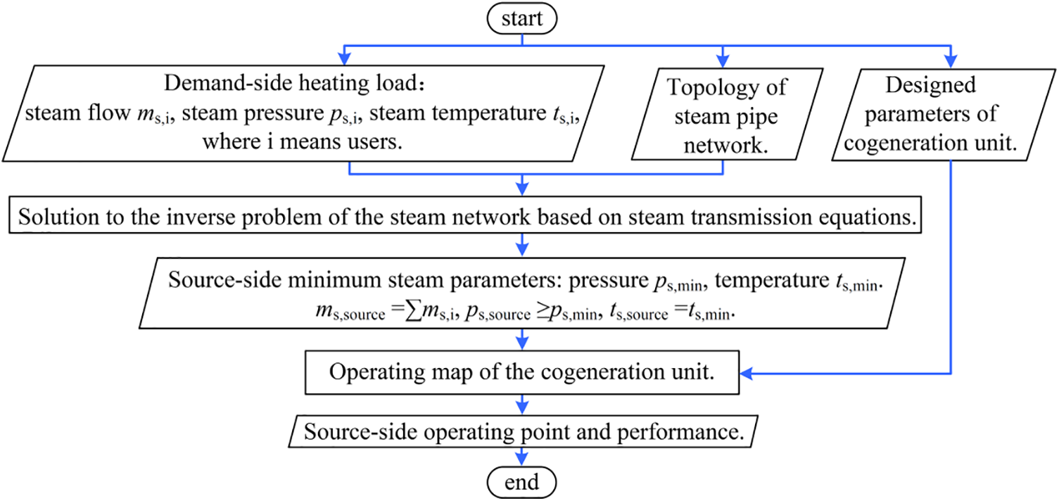
Figure 1: Technical procedure of the work
2 Description of the Cogeneration System and the Performance Indicators
2.1 Source-Side Cogeneration Unit
A 1 on 1 gas-steam combined cycle cogeneration unit with dual shafts at the source side is sketched as Fig. 2. It is composed of one M701F4 gas turbine, one BHDB-M701F4-Q1 three-pressure reheat natural cycle waste heat boiler, one LCC145/112-10.9/2.3/1.3/566/566 steam turbine and two generators. The steam for heating rated at 1.3 MPa is extracted from the intermediate-pressure steam cylinder. Under the guaranteed performance conditions [35], i.e., the ambient temperature
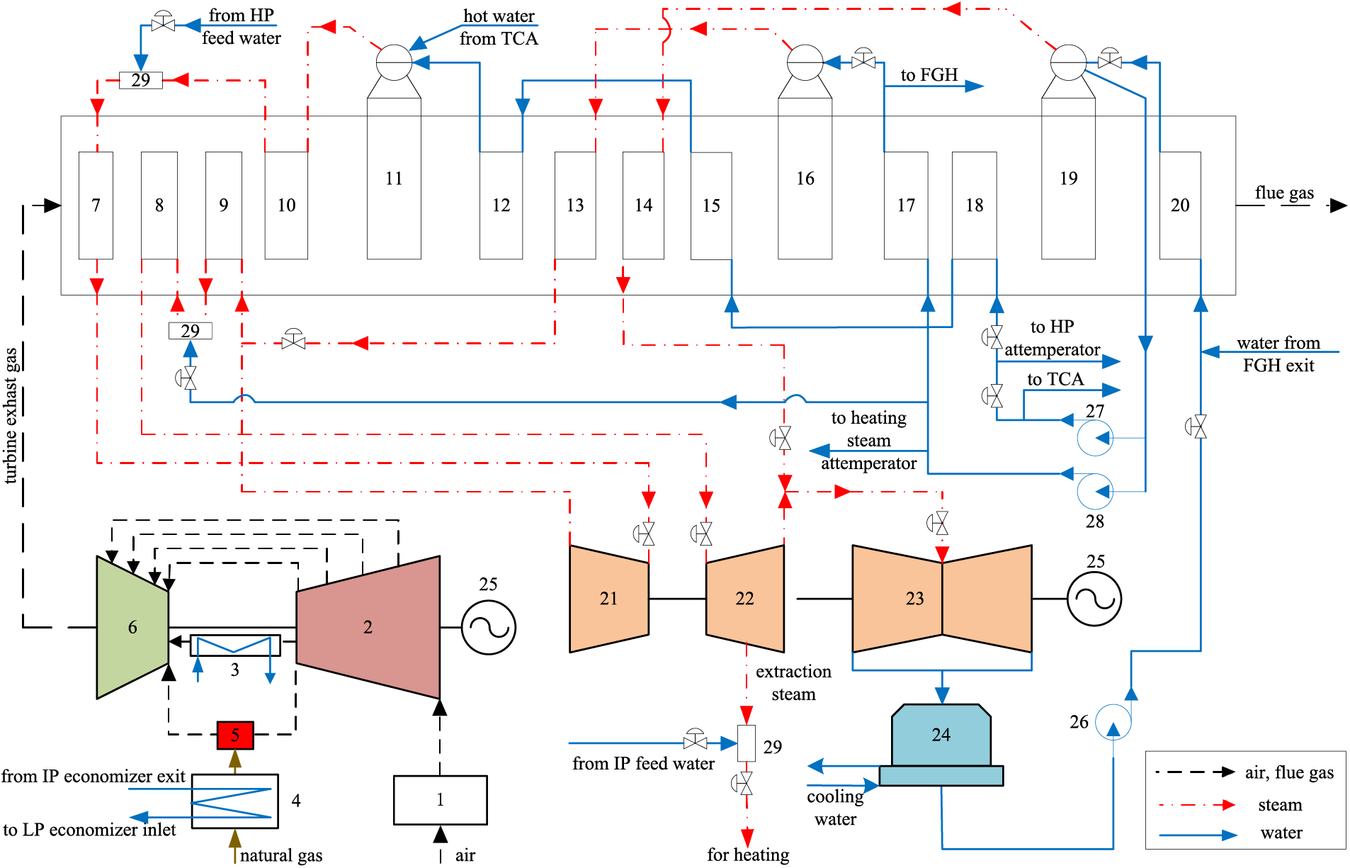
Figure 2: System sketch of gas-steam combined cycle cogeneration unit (1—air filter; 2—compressor; 3—TCA; 4—FGH; 5—combustion chamber; 6—turbine; 7—HP superheater Ⅱ; 8—reheater Ⅱ; 9—reheater Ⅰ; 10—HP superheater Ⅰ; 11—HP evaporator; 12—HP economizer III; 13—IP superheater; 14—LP superheater; 15—HP economizer Ⅱ; 16—IP evaporator; 17—IP economizer; 18—HP economizer Ⅰ; 19—LP evaporator; 20—LP economizer; 21—HP steam turbine; 22—IP steam turbine; 23—LP steam turbine; 24—condenser; 25—generator; 26—condensate pump; 27—HP feed water pump; 28—IP feed water pump; 29—attemperator)
In addition, the gas-steam combined cycle cogeneration unit also has the following design features:
1) There is a complicated heat exchange between the gas turbine and the HRSG (heat recovery steam generator). Part of the high-pressure feed water is used for the turbine rotor cooling air system (TCA) and finally returns to the high-pressure drum. Part of the feed water at the outlet of the intermediate-pressure economizer is used for fuel gas heating (FGH) and finally enters the inlet of the low-pressure economizer.
2) Intermediated-pressure steam is extracted for heating, and the source-side heating parameters can be adjusted by the desuperheater, pressure regulator, control rotary diaphragm, and gas turbine load.
3) The cogeneration system includes two combined cycle units. Under the performance guarantee conditions, when the source-side heating steam pressure is 1.10 MP and the temperature is not lower than 238.8°C, the maximum extraction steam flow of a single unit is about 117.2 t/h.
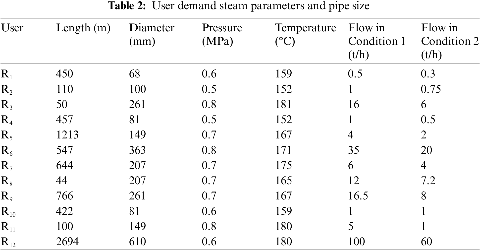
As a research case from a cogeneration unit, the heating steam network is divided into two lines: (1) The eastern line is about 4.2 km long, and (2) the western line is about 14.5 km long. The pipeline is mainly arranged in directly-buried modes, whereas a small part of the pipeline is laid by overhead or in-duct installation. Double-layer composite insulation structures are designed for the pipeline, which are calcium silicate insulation and polyurethane foam. There is 1 steam source point of a cogeneration plant, 12 terminal thermal user nodes (R1-R12), and 22 pipelines. The simplified layout structure is shown in Fig. 3.
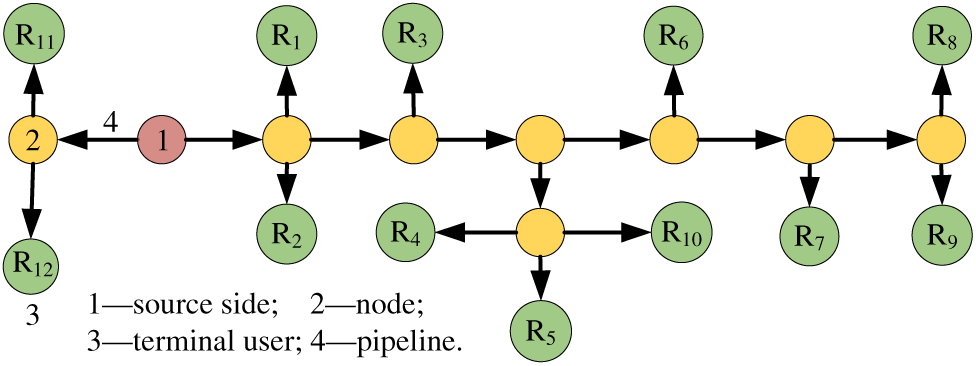
Figure 3: Layout of heating pipe network
2.2.2 Pipe Insulation Structure
There are three ways for the arrangement of heating steam pipelines, i.e., in-duct arrangement, directly-buried installation, and overhead installation [36]. To reduce temperature drop, long-distance heating steam pipelines need to be wrapped by multiple layers of insulation materials. The section of pipelines with two layers of insulation structure is shown in Fig. 4. The heating steam flows in the inner section of the steel pipe with the inside diameter
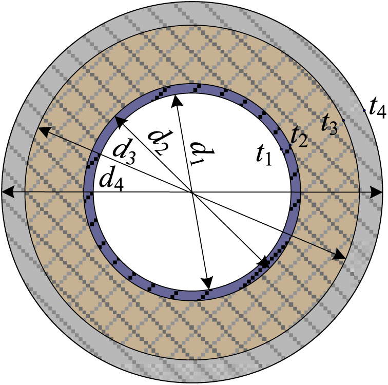
Figure 4: Sectional structure of pipe
2.2.3 Pipe Network Size and Typical Heating Parameters
1) Designed heating condition (Condition 1).
The designed heating condition is characterized by low parameters and a large flow rate. The source-side steam pressure

2) Verification condition (Condition 2).
This condition was used for verifying the calculation of the network design, which is characterized by high parameters and a small flow rate. The source-side pressure
3) Pipe network dimension.
The pipe dimensions determined under the design conditions are shown in Table 2.
2.3.1 Comprehensive Thermal Efficiency
During a statistical period, the average electric power supply of the combined cycle cogeneration unit is denoted as
When the fuel price is denoted as
In general, set the ratio of energy price to fuel price
2.3.3 Power Peak Regulation Depth
The power peak regulation depth
where,
3 Operating Maps of the Cogeneration Unit
3.1 Simulation of Off-Design Performance
The design working condition model established by GT-PRO can be imported into THERMOFLEX to build the operating model and subsequently to analyze the off-design performance [38,39]. The physical modeling process of a gas-steam combined cycle with THERMOFLEX is described as follows:
1) Import the design model built by GT-PRO, verify the model and simulate the design performance;
2) Set macro variables: Research object M701F4 gas turbine; The molar composition of the fuel is measured as 89.85% CH4, 4.92% C2H6, 0.49% C3H8, 0.15% C4H10, 0.03% C5H12, 0.92% N2, 3.49% CO2. The lower heating value is 44645.8 kJ/kg. The ambient is set as the testing conditions;
3) Off-design performance simulation: Build up the flow diagram of the cogeneration unit according to the system as shown in Fig. 2. The input variables include the load rate of the gas turbine and the flow rate of extraction steam for heating. The output variables are mainly the quantities of electric power, extraction steam parameters, and fuel flow of the combined cycle cogeneration unit.
3.1.2 Validation of the Simulation
The performance test covered two different operating conditions, which were used to validate the simulation. In Case 1, the power load of the combined cycle unit

3.2 Operating Maps and Efficiency of the Cogeneration Unit under Various Conditions
3.2.1 Operating Maps at Various Ambient Temperatures and Extraction Steam Pressures
The operating maps of the cogeneration unit at various ambient temperatures and extraction steam pressures are presented in Fig. 5.
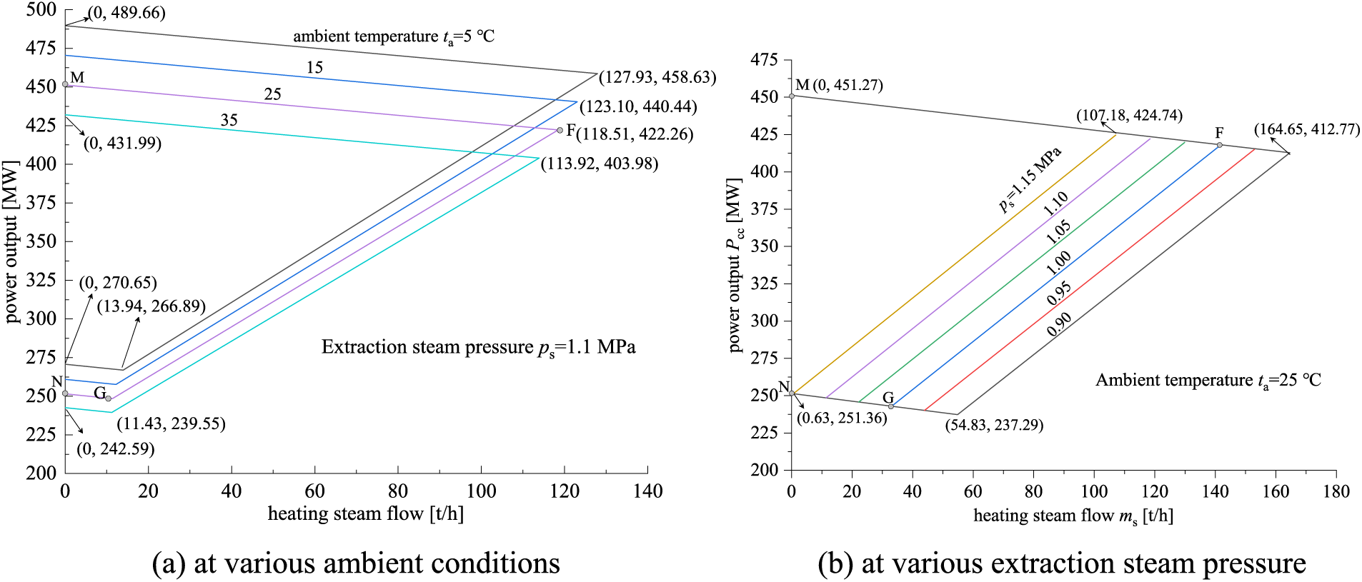
Figure 5: Operating maps of the cogeneration unit
Taking
The operating maps at various extraction steam pressures are presented in Fig. 5b. They show that the available operating domain considerably narrows with the rise of the extraction steam parameters. This indicates that an optimized source-side pressure would enhance peak-regulation depth.
As the overall load-extracted steam temperature can meet the user demand, the operating maps at various heating steam temperatures are excluded in the present work.
3.2.2 Operating Comprehensive Efficiency
Taking the ambient temperature
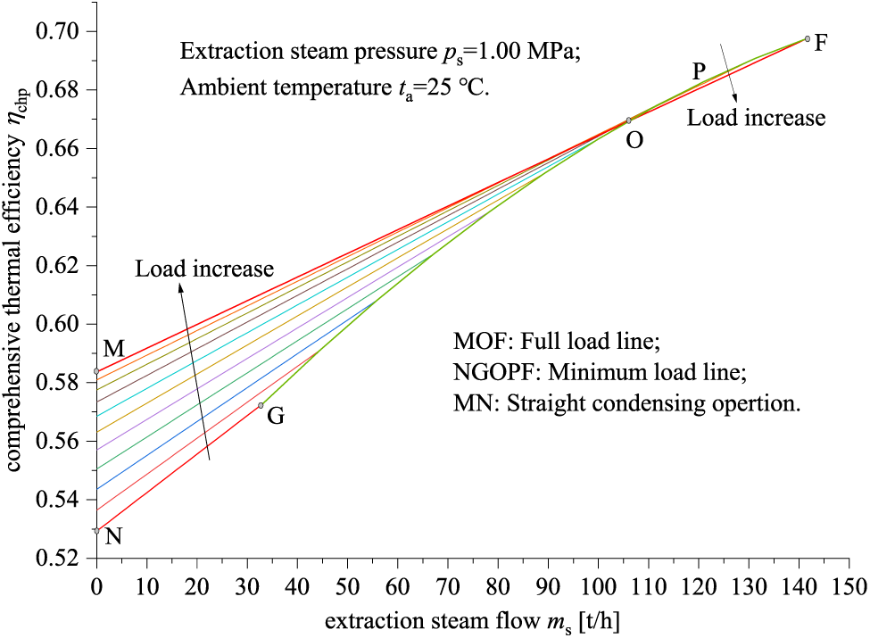
Figure 6: Operating comprehensive thermal efficiency of the cogeneration unit
As can be seen from Fig. 6, the comprehensive thermal efficiency increases with the rise of the heating load. However, at a constant heating load, the comprehensive thermal efficiency at a higher power load is greater in the M-N-G-O operating domain; whereas within the O-P-F domain, the comprehensive thermal efficiency is greater at a lower power load. This is caused by the combined influence of the power efficiency and the heating/power ratio at part-load conditions. For example, in the O-P-F domain, although the power load and the efficiency of the cogeneration unit are relatively low, the heating/power ratio is greater when meeting a certain heating load, and the cold-end thermal loss rate of the steam turbine is relatively reduced.
4 Solution of the Inverse Problem in Complex Steam Network
4.1 Heat Transfer in Long-Distance Steam Pipelines
The total heat transfer resistance
The total heat-transfer coefficient
where,
The steam flow belongs to forced convection in the pipeline, where the Reynolds number (
where,
In the case of overhead installation, the coefficient of convection heat transfer outside the pipe (
where,
In the directly buried installation, the external structure of the pipeline is directly in contact with the soil, and the heat transfer characteristics belong to the first type of boundary conditions. The convective heat transfer coefficient of the pipeline to the soil is mainly related to the thermal conductivity of the soil, the diameter of the steam pipeline, as well as the depth of the direct installation of the pipeline, etc. The heat transfer coefficient is calculated using the theoretical formula derived by Volchgaimer [41]:
where,
4.2 The Basic Governing Equation and Forward Solution of Hydraulic and Thermodynamic Coupling
Steam flow in the heating networks is regarded as a steady model in this paper to avoid complex numerical solutions. The simplified basic governing equations of hydraulic-thermal coupling performance are as follows.
For one-dimensional steady flow, the continuity equation in the steam pipes can be expressed as:
The forces acting on per unit volume of the steam in a pipe include pressure, gravity, and friction. These forces balance with the momentum variation. Hence, the momentum equation can be written as:
The energy equation indicates the conversion of the thermodynamic energy with the potential energy and the heat transferring to the surroundings, which can be approximately derived as:
The steam properties depend on the pressure and temperature, which can be expressed as:
where,
The friction resistance coefficient
where,
4.2.2 Forward Solution Procedure
At steady flow, the above partial differential equations for a basic control system, as expressed in Eqs. (11)–(14), can be numerically solved using the four-order classical Runge-Kutta method. In the forward solution procedure as shown in Fig. 7, the steam temperature
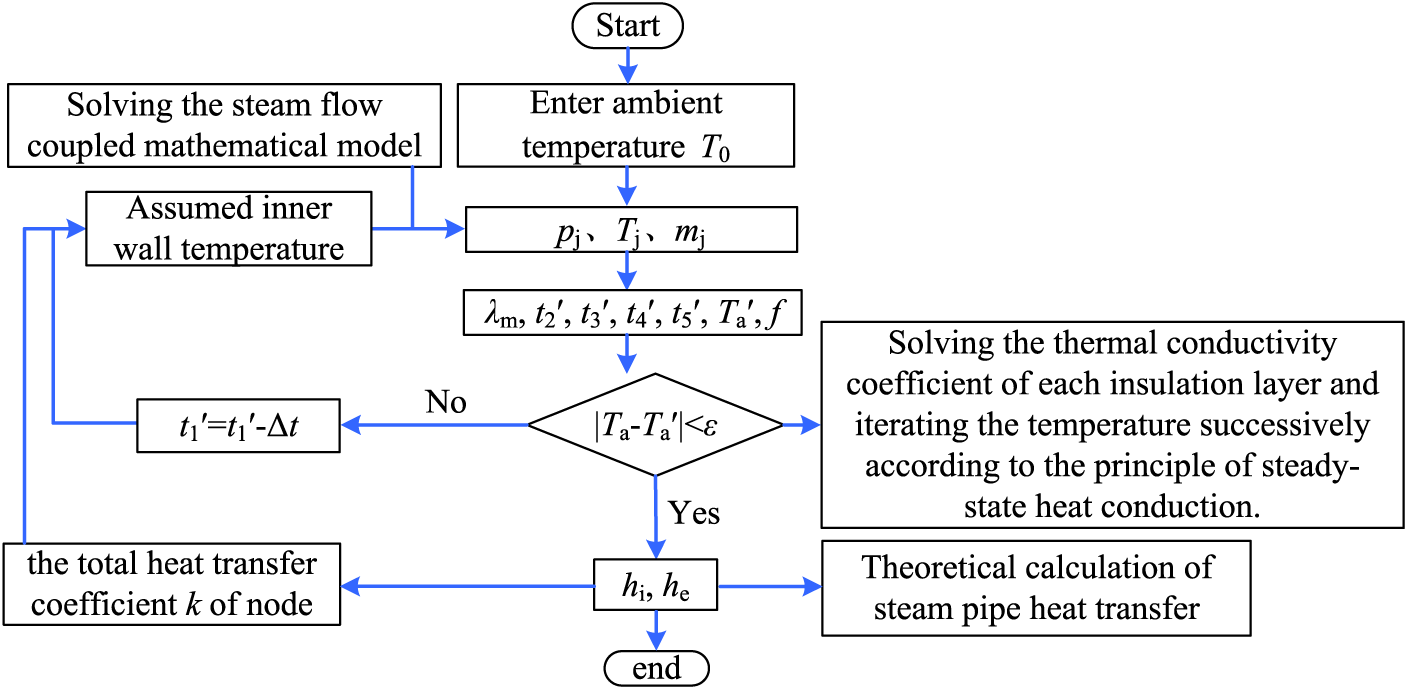
Figure 7: Solution procedure of the forward problem in hydraulic-thermal performance
4.2.3 Validation of Complex Heating Network Modeling
The steam parameter calculation in a large complex heating pipeline network is based on the known initial heating parameter of the thermal power plant, which belongs to a forward problem. The outlet steam parameters of a certain pipe section can be solved based on the coupling model of hydraulic and thermal calculation. The calculation result in the terminal pipe section can be saved in a matrix form by combining it with the graph theory correlation matrix [42], so that it can be accessed and transmitted to the next node section as the initial input. Thus, the steam parameters of the inlet and outlet nodes of each pipe section in the whole heating network can be solved.
In the case of the simplified topology, as described in Fig. 3, the comparison between the model value and the original design data under Condition 1 is shown in Fig. 8, where the original data are obtained from the design report of the cogeneration plant. As can be seen from Fig. 8a, the steam pressure on the demand sides shows a high coincidence with the reference data. The relative error at R3 is the smallest, which is 0.11%. The relative error of steam pressure at user R8 is the largest with 1.82%. Fig. 8b also indicates a good agreement with the reference data. The relative error of temperature at user R6 is the smallest at 0.28%. The relative error in steam temperature at R4 is the largest with 4.76%.

Figure 8: Validation of complex heating network modeling at Condition 1
The comparison between the calculation results and the reference data under Condition 2 is shown in Fig. 9. It shows a good accordance in the terminal steam temperature and pressure. The maximum relative error of pressure at R1 is 1.33%, and the maximum relative error of temperature is 1.65%. The error of the steam parameters is less than 5%, which indicates that the hydraulic-thermal coupling model is reasonable and effective. Thus, the model can be used for further optimization of source-side heating parameters.
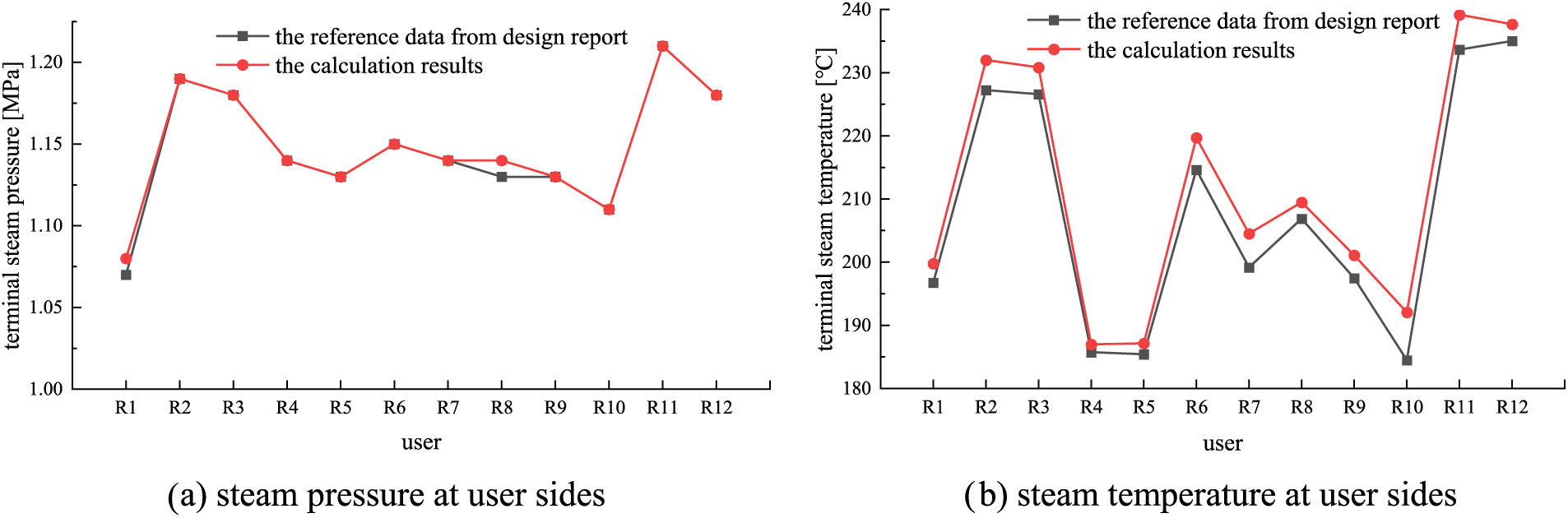
Figure 9: Validation of complex heating network modeling at Condition 2
4.3 Inverse Solution of Hydraulic and Thermodynamic Coupling
4.3.1 Inverse Solution Procedure
The user-side steam parameters and load vary commonly according to the industrial process. On the basis of heating quality requirements and the normal operation of the pipeline network, the steam parameters on the source side need to be rationally scheduled according to the demand load, to reduce the cost of steam transmission and promote the economics of the cogeneration plant. Therefore, it is significant to solve the minimum heating parameters on the source side, which belongs to an inverse problem of hydraulic-thermal coupling.
The procedure of inverse solution for source-side heating steam parameters is shown in Fig. 10. The inverse solution means: Determining the optimization target or the minimum steam parameters on the source side of the heating network according to the boundary constraint conditions, i.e., the demand-side heating load on the user side and the structure parameters of the steam pipelines. The solution process is based on the hydraulic-thermal coupling model. In this solution, the steam parameter on the source side is unknown, which can be pre-initialized and iterated until the calculated terminal steam parameters meet the demand.
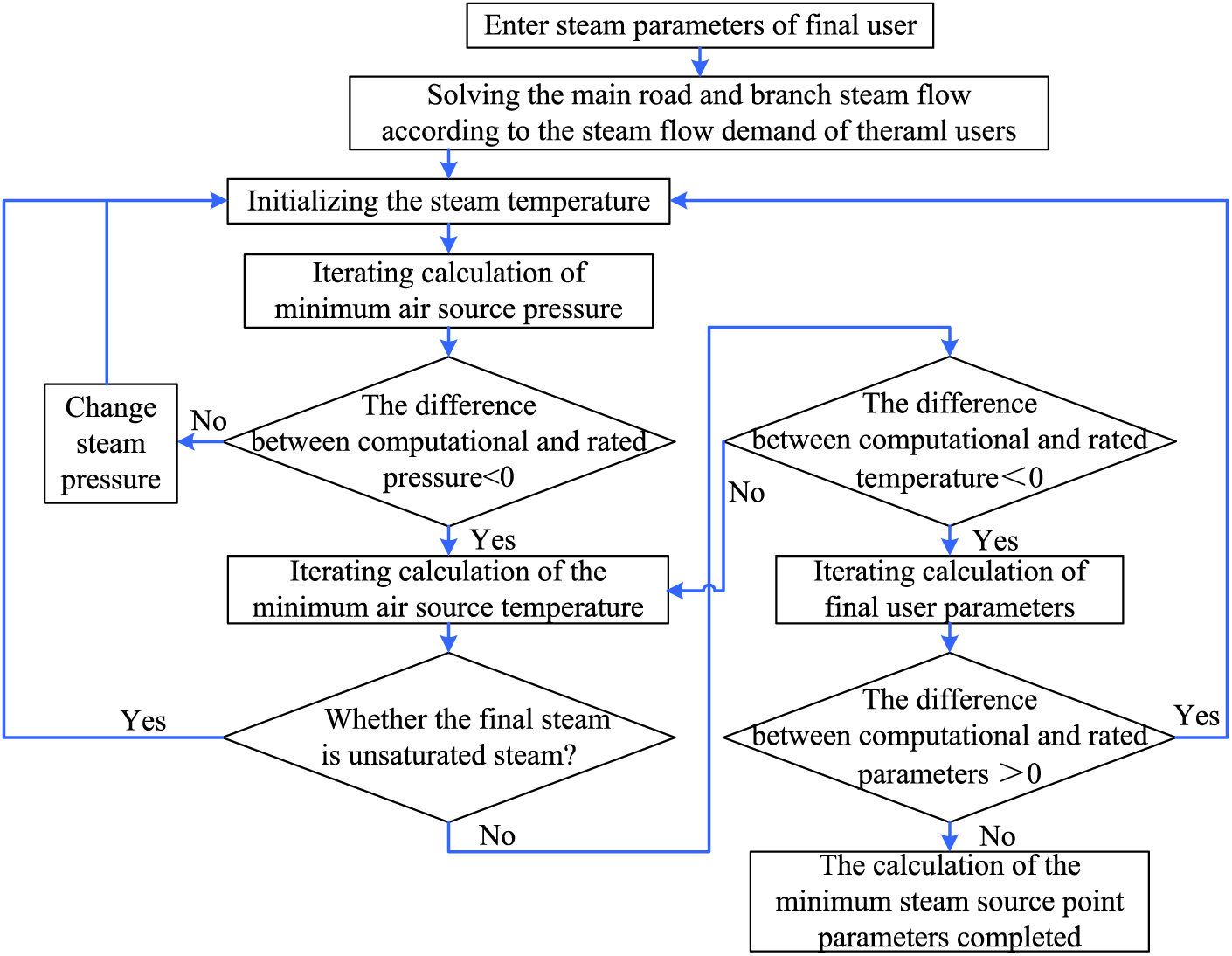
Figure 10: Inverse solution procedure of source-side steam parameters
4.3.2 Inverse Solution of Heating Steam Parameters at Designed Load
Network operating Condition 1 as shown in Table 1 is used to verify the availability of the inverse solution for minimum steam parameters at source sides. According to the solution process shown in Fig. 11, under operating Condition 1, the twin cogeneration units can operate normally and meet the rated steam flow requirements. The minimum steam parameters on the source side are determined as 1.074 MPa and 191.15°C, with the superheat degree 54.33°C and 8.138°C, respectively. It should be noted that, the superheat degree of the source-side heating steam is considerably lower than the original value. This is because the flow resistance increases at higher steam flow, which partly makes up for the temperature drop.
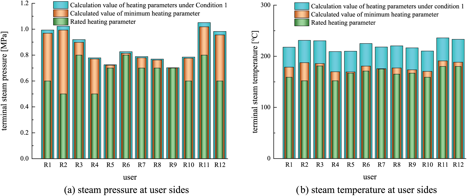
Figure 11: Comparison of user-side steam parameters with the original design values
The calculated steam parameters on the demand sides are compared with the original design values, as shown in Fig. 11, where, the original design values are plotted in blue; while the optimized values are in orange. It can be seen that, in the case of a heating supply with the minimum steam parameters, both the steam temperature and pressure on all the user sides are greater than the demand values. This means the steam parameters on the source side after inverse optimization are lower than the original values, whereas can meet the demand of the users. The deviation between the original design and the optimized values are average of 0.0156 MPa in the source-side steam pressure and 42.54°C in the temperature. Reducing the steam temperature and pressure on the source side can decrease the energy loss and operation cost of cogeneration plants. Therefore, the inverse solution of source-side steam parameters provides a meaningful reference for optimizing the operation of heating networks.
4.3.3 Influence of Heating Load on the Minimum Steam Parameters on the Source Side
The heating load fluctuation, caused by the different requirements of users with different industrial processes, should be taken into consideration when solving the minimum steam parameters on the source side. Taking operating Condition 1 as an example, the variation range of the heating load is set to be 30%~100%. The influence of the heating load on the minimum steam parameters of the source side is investigated, which is shown in Fig. 12. As can be seen, the minimum steam pressure on the source side decreases with the reduction of the heating load. At higher heating load, the minimum steam pressure drops faster. The reason is that, with the reduction of the heating load or the heating steam flow, the pressure loss in the pipeline drops. For example, when the heating load reduces from 90% to 80%, the minimum steam pressure can be optimized and reduced by 0.041 MPa, i.e., from 1.019 to 0.978 MPa. When the heating load lowers from 90% to 80%, the minimum steam pressure on the source side decreases by 0.055 MPa.
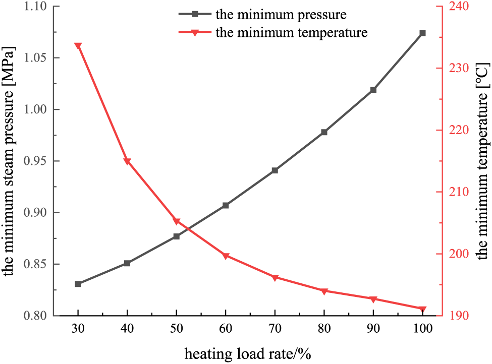
Figure 12: Effect of demand-side heating load on the minimum source-side steam parameters
In addition, the minimum temperature of the heating steam on the source side rises with the decrease of the demand-side heating load, especially at lower heating loads. At higher heating loads, the variation rate of the minimum temperature slows down obviously. The main reason is that, the temperature reduction increases as the decrement in the heating steam flow resulting from the steam retention time in the pipelines. Therefore, to meet the temperature requirements on the demand sides at lower heating loads, the extracted steam temperature on the source side will increase significantly. For example, when the heat load ranges in 60%~50%, the minimum steam temperature on the source side gradually increases from 199.75°C to 205.35°C. When the heating load de-mand decreases by 1%, the minimum temperature average increases by 0.56°C. However, when the heating load reduces from 40% to 30%, the minimum temperature increases significantly from 215.05°C to 233.75°C. On average, every 1% reduction of the heating load brings about an increment of 1.87°C in the minimum temperature on the source side.
5 Discussion on the Cogeneration Performance
5.1 Different Source-Side Steam Parameters for Comparison
The cogeneration performance indicators, i.e., comprehensive thermal efficiency
1) The original designed conditions, where the source-side steam pressure
2) The minimum source-side steam parameters by inverse solution, where the source-side
It has been demonstrated in Section 4 that the above two groups of steam parameters can meet the heating load as described in Condition 1 (see Table 2). Please note, the designed heating load is functioned by twin cogeneration units. Each of the units operates equally at the heating load of
5.2 Comparison of the Performance Indicators
5.2.1 Power Peak Regulation Depth and Comprehensive Thermal Efficiency
The ambient conditions and the main operating parameters at the different source-side steam conditions are presented in Table 4. To meet the user-side heating load, the cogeneration unit has to operate at a power load no less than the minimum, which means a “following thermal load”.
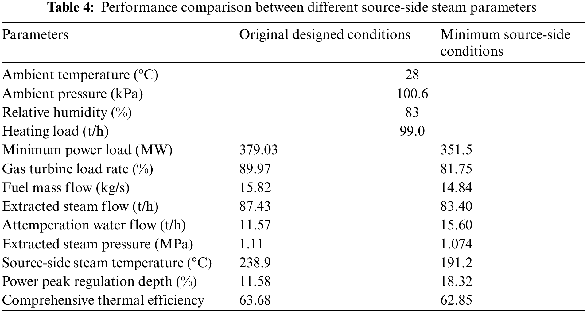
As can be seen from Table 4, the minimum power load determined by the heating load is 379.03 MW at the original designed conditions, which remarkably decreases to 351.5 MW at the minimum source-side heating conditions. This indicates a positive enhancement in the power regulation capacity. At the full power load of the cogeneration unit, the maximum power load can be determined by the operating maps, i.e.,
The comprehensive thermal efficiency
At a fuel price
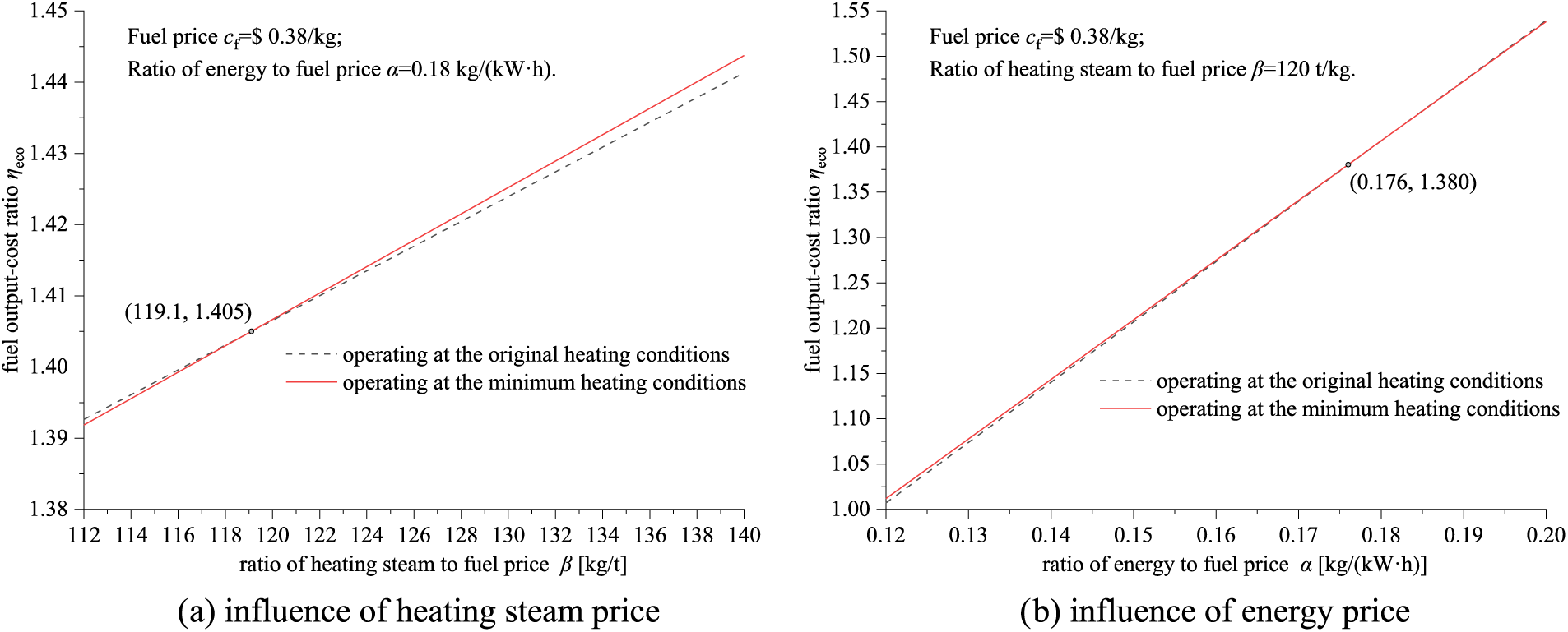
Figure 13: Comparison of fuel output-cost ratio at different heating conditions
It can be found from Fig. 13b that, the influence of the energy-fuel price ratio
Taking a steam network supported by a cogeneration project in South China as the research case, the interaction effect among the source-side prime movers, the heating networks, and the terminal demand thermal parameters is investigated based on the designed values, the plant testing data, and the validated simulation. Given the overall CHP system including the prime mover, the steam network, and the terminal users, the operating performance of the cogeneration unit is discussed. The main conclusions are summarized as follows:
• The power capacity and the heating capacity increase with the reduction in the ambient temperature. The available operating domain considerably narrows with the rise of the extraction steam pressure and flow.
• The inverse solution of source-side steam parameters shows that, at rated heating load, the source-side steam pressure and temperature can be optimized from the originally designed 1.11 MPa and 238.8°C to 1.074 MPa and 191.15°C, respectively.
• When the heating loads on the user sides decrease from 100% to 30%, the minimum steam pressure on the source side decreases from 1.074 to 0.831 MPa, meanwhile, the minimum temperature increases from 191.15°C to 233.75°C, respectively.
• The power peak regulation depth remarkably increases whereas the comprehensive thermal efficiency decreases under the operating strategy with minimum source-side heating parameters. The power peak regulation depth is 11.58% at the original heating conditions and 18.30% at the minimum source-side heating conditions, respectively.
• The operation strategy with the minimum source-side heating steam parameters can be superior to the original one in the economy at a higher price of the heating steam. At a fuel price $0.38/kg and the energy to fuel price of 0.18 kg/(kW·h), the critical price ratio of heating steam to fuel is 119.1 kg/t. The influence of the energy-fuel price ratio on the economic deviation appears relatively weak.
The contributions of this research include 1) Cogeneration operating maps at off-design steam parameters extracted for heating; 2) Inverse solution to the source-side minimum steam parameters in the heating network; 3) Enhancement in the power regulation depth under minimum steam parameters. The determination of source-side extracted heating parameters is of great significance to the economic operation of the cogeneration systems.
Acknowledgement: The authors also give thanks to Feng Wu, Runke Xiao and Qing Yin for their preliminary editing of the manuscript.
Funding Statement: This work was supported by Guangdong Province Key Laboratory of Efficient and Clean Energy Utilization (South China University of Technology) (2013A061401005), and by Research Fund (JMSWFW-2110-044) from Zhongshan Jiaming Electric Power Co., Ltd.
Author Contributions: Guanglu Xie: General Manager, supervision and management. Zhimin Xue: Manager of Production Technology Department, performance testing and system design. Bo Xiong: Deputy General Manager, management and performance testing. Yaowen Huang: Vice Manager of Maintenance Department, performance testing. Chaoming Chen: Manager of Operation Department, performance testing; Qing Liao: Vice Manager of Operation Department, performance testing. Cheng Yang: Writing, review & editing, methodology, formal analysis. Xiaoqian Ma: Supervision and conceptualization.
Availability of Data and Materials: Data will be made available on request.
Conflicts of Interest: The authors declare that they have no conflicts of interest to report regarding the present study.
References
1. Nie, Y., Deng, M., Shan, M., Yang, X. (2023). Clean and low-carbon heating in the building sector of China: 10-Year development review and policy implications. Energy Policy, 179, 113659. 10.1016/j.enpol.2023.113659 [Google Scholar] [CrossRef]
2. James, T. O. (2012). Biomass CHP and thermal projects for federal facilities. Energy Engineering, 109, 21–37. 10.1080/01998595.2012.10554227 [Google Scholar] [CrossRef]
3. Tian, X., Sun, J., Xu, T., Cui, M., Wang, X. et al. (2022). Dynamic simulation and performance analysis on multi-energy coupled CCHP system. Energy Engineering, 119(2), 723–737. 10.32604/ee.2012.015982 [Google Scholar] [CrossRef]
4. İncili, V., Dolgun, G. K., Keçebaş, A., Ural, T. (2023). Energy and exergy analyses of a coal-fired micro-CHP system coupled engine as a domestic solution. Energy, 274(1), 127400. 10.1016/j.energy.2023.127400 [Google Scholar] [CrossRef]
5. Wang, X., Duan, L. (2022). Peak regulation performance study of the gas turbine combined cycle based combined heating and power system with gas turbine interstage extraction gas method. Energy Conversion and Management, 269(1), 116103. 10.1016/j.enconman.2022.116103 [Google Scholar] [CrossRef]
6. Fan, D., Shi, C., Sun, K., Lu, X. (2020). Operation strategy analysis and configuration optimization of solar CCHP system. Energy Engineering, 118, 1197–1121. 10.32604/EE.2021.014532 [Google Scholar] [CrossRef]
7. Huang, R., Lu, X., Liang, Z., Gao, P., Liang, T. (2022). Modeling and simulation analysis of solar thermal electric plants based on Petri net. Energy Engineering, 119, 1711–1728. 10.32604/ee.2022.019128 [Google Scholar] [CrossRef]
8. Yang, C., Liu, H., Wang, P., Fan, K., Huang, Z. et al. (2020). Economic analysis on peak-regulation of GTCC cogeneration unit with extraction heating. Proceedings of the CSEE, 40(2), 592–600 (In Chinese). 10.13334/j.0258-8013.pcsee.191282 [Google Scholar] [CrossRef]
9. Guelpa, E., Capone, M., Sciacovelli, A., Vasset, N., Baviere, R. et al. (2023). Reduction of supply temperature in existing district heating: A review of strategies and implementations. Energy, 262, 125363. 10.1016/j.energy.2022.125363 [Google Scholar] [CrossRef]
10. Almajali, M. R., Quran, O. A. S. (2021). Parametric study on the performance of combined power plant of steam and gas turbines. Journal of Thermal Science and Engineering Applications, 13(5), 051006. 10.1115/1.4049753 [Google Scholar] [CrossRef]
11. Akbar, G. S., Salarian, H., Ataei, A. (2019). A novel approach to integration of hot oil and combined heat and power systems through pinch technology and mathematical programming. Energy Sources, Part A: Recovery, Utilization, and Environmental Effects, 41(24), 2026–3045. 10.1080/15567036.2019.1583695 [Google Scholar] [CrossRef]
12. Pang, J., Ge, Z., Zhang, Y., Du, X. (2023). Comparative designs and optimizations of the steam ejector for a CHP system. Applied Thermal Engineering, 226(25), 120345. 10.1016/j.applthermaleng.2023.120345 [Google Scholar] [CrossRef]
13. Chen, L., Huang, H., Tang, P., Yao, D., Yang, H. et al. (2022). Optimal modeling of combined cooling, heating, and power systems using developed African vulture optimization: A case study in watersport complex. Energy Sources, Part A: Recovery, Utilization and Environmental Effects, 44(2), 4296–4317. 10.1080/15567036.2022.2074174 [Google Scholar] [CrossRef]
14. Zhang, S., Song, G., Xue, Z. (2021). Techno-economic assessment of enamel heat pipe exchanger in a combined heat and power plant with back pressure turbine. Journal of Thermal Science and Engineering Applications, 13(4), 044501. 10.1115/1.4049429 [Google Scholar] [CrossRef]
15. Yu, J., Shen, X., Sun, H. (2019). Economic dispatch for regional integrated energy system with district heating network under stochastic demand. IEEE Access, 7, 46659–46667. 10.1109/ACCESS.2019.2905772 [Google Scholar] [CrossRef]
16. Liu, M., Liu, M., Chen, W., Yan, J. (2023). Operational flexibility and operation optimization of CHP units supplying electricity and two-pressure steam. Energy, 263(15), 125988. 10.1016/j.energy.2022.125988 [Google Scholar] [CrossRef]
17. Xie, W., Li, Q., Yang, Y., Wei, Q. (2021). Collaborative scheduling of source-network-load-storage considering thermal inertia of the integrated electricity and district heating systems. Energy Sources, Part A: Recovery, Utilization, and Environmental Effect. 10.1080/15567036.2021.2006369 [Google Scholar] [CrossRef]
18. Haase, P., Thomas, B. (2021). Test and optimization of a control algorithm for demand-oriented operation of CHP units using hardware-in-the-loop. Applied Energy, 294, 116974. 10.1016/j.apenergy.2021.116974 [Google Scholar] [CrossRef]
19. Brost, F., Strobel, N., Kohne, T., Weigold, M. (2021). Investigating the electrical demand-side management potential of industrial steam supply systems using dynamic simulation. Energies, 14, 1533. 10.3390/en14061533 [Google Scholar] [CrossRef]
20. Jakubek, D., Ocłoń, P., Nowak-Ocłoń, M., Sułowicz, M., Varbanov, P. S. et al. (2023). Mathematical modelling and model validation of the heat losses in district heating networks. Energy, 267, 126460. 10.1016/j.energy.2022.126460 [Google Scholar] [CrossRef]
21. Wang, L., Yue, X., Chong, D., Chen, W., Yan, J. (2018). Experimental investigation on the phenomenon of steam condensation induced water hammer in a horizontal pipe. Experimental Thermal and Fluid Science, 91, 451–458. 10.1016/j.expthermflusci.2017.10.036 [Google Scholar] [CrossRef]
22. Steinegger, J., Wallner, S., Greiml, M., Kienberger, T. (2023). A new quasi-dynamic load flow calculation for district heating networks. Energy, 266, 126410. 10.1016/j.energy.2022.126410 [Google Scholar] [CrossRef]
23. Nault, J. D., Karney, B. W. (2021). Comprehensive adaptive modeling of 1-D unsteady pipe network hydraulics. Journal of Hydraulic Research, 59(2), 263–279. 10.1080/00221686.2020.1770878 [Google Scholar] [CrossRef]
24. Zhong, W., Feng, H., Wang, X., Wu, D., Xue, M. et al. (2015). Online hydraulic calculation and operation optimization of industrial steam heating networks considering heat dissipation in pipes. Energy, 87, 566–577. 10.1016/j.energy.2015.05.024 [Google Scholar] [CrossRef]
25. Guo, S., Ji, W., Wang, C., Song, T., Wang, J. (2023). Hydraulic-thermal coupling dynamic models based on mechanism and data-driven methods of the heating networks in integrated energy systems. Energy Conversion and Management, 292, 117353. 10.1016/j.enconman.2023.117353 [Google Scholar] [CrossRef]
26. Kumar, B. N., Reddy, K. S. (2018). Comparison of two-phase flow correlations for thermo-hydraulic modelling of direct steam generation in a solar parabolic trough collector system. Journal of Thermal Science and Engineering Applications, 10(4), 041005. 10.1115/1.4038988 [Google Scholar] [CrossRef]
27. Liu, X., Zhang, Y., Hou, X., Zhao, J., Sun, Y. et al. (2021). Analysis of transmission characteristics of steam long-distance heating pipeline. Energy Reports, 7, 242–253. 10.1016/j.egyr.2021.10.034 [Google Scholar] [CrossRef]
28. Qin, X., Sun, H., Shen, X., Guo, Y., Guo, Q. et al. (2019). A generalized quasi-dynamic model for electric-heat coupling integrated energy system with distributed energy resources. Applied Energy, 251(1), 113270. 10.1016/j.apenenergy.2019.05.073 [Google Scholar] [CrossRef]
29. Wang, H., Wang, H., Zhu, T., Deng, W. (2017). A novel model for steam transportation considering drainage loss in pipeline networks. Applied Energy, 188, 178–189. 10.1016/j.apenergy.2016.11.131 [Google Scholar] [CrossRef]
30. Guelpa, E., Verda, V. (2019). Compact physical model for simulation of thermal networks. Energy, 175, 998–1008. 10.1016/j.energy.2019.03.064 [Google Scholar] [CrossRef]
31. Zhou, S., Chen, J., Gu, W., Fang, X., Yuan, X. (2023). An adaptive space-step simulation approach for steam heating network considering condensate loss. Energy, 263, 125643. 10.1016/j.energy.2022.125643 [Google Scholar] [CrossRef]
32. Yang, W., Huang, Y., Zhao, D. (2023). A coupled hydraulic-thermal dynamic model for the steam network in a heat-electricity integrated energy system. Energy, 263, 125800. 10.1016/j.energy.2022.125800 [Google Scholar] [CrossRef]
33. Zhong, W., Zhang, S., Lin, X., Wang, J., Zhou, Y. (2023). Quantitative study on steam system thermal inertia based on a dynamic hydraulic analytical model. Journal of Cleaner Production, 403(1), 136864. 10.1016/j.jclepro.2023.136864 [Google Scholar] [CrossRef]
34. Ge, Z., Liang, H., He, J., Chen, Q. (2018). Design of a complex heat supply pipe network based on the graph theory. Journal of Engineering for Thermal Energy and Power, 33(6), 94–98+114 (In Chinese). 10.16146/j.cnki.rndlgc.2018.06.016 [Google Scholar] [CrossRef]
35. Le, Z., Liang, Y., Xiong, B., Huang, Y., Niu, H. et al. (2023). Comparison of model-driven soft measurement methods for compressor air flow in gas-steam combined cycle power units. Flow Measurement and Instrumentation, 94, 102462. 10.1016/j.flowmeasinst.2023.102462 [Google Scholar] [CrossRef]
36. Cui, C., Shen, J., Zhang, J. (2022). Dynamic modeling and characteristic analysis of the double-reactor and quadruple-turbine nuclear power system based on steam main-pipeline distribution characteristics. Annals of Nuclear Energy, 170(1), 108986. 10.1016/j.anucene.2022.108986 [Google Scholar] [CrossRef]
37. Xiao, R., Yang, C., Qi, H., Ma, X. (2023). Synergetic performance of gas turbine combined cycle unit with inlet cooled by quasi-isobaric ACAES exhaust. Applied Energy, 352, 122019. 10.1016/j.apenergy.2023.122019 [Google Scholar] [CrossRef]
38. Pan, Z., Lin, Z., Fan, K., Yang, C., Ma, X. (2021). Off-design performance of gas turbine power units with alternative load-control strategies. Energy Engineering, 118(1), 119–141. 10.32604/EE.2020.013585 [Google Scholar] [CrossRef]
39. Fan, K., Yang, C., Xie, Z., Ma, X. (2021). Load-regulation characteristics of gas turbine combined cycle power system controlled with compressor inlet air heating. Applied Thermal Engineering, 196, 117285. 10.1016/j.applthermaleng.2021.117285 [Google Scholar] [CrossRef]
40. Winterton, R. H. S. (1998). Where did the Dittus and Boelter equation come from? International Journal of Heat and Mass Transfer, 41(4–5), 809–810. 10.1016/S0017-9310(97)00177-4 [Google Scholar] [CrossRef]
41. Yuan, Q., Lou, Y., Shi, T., Gao, Y., Wei, J. et al. (2023). Investigation into the heat transfer models for the hot crude oil transportation in a long-buried pipeline. Energy Science & Engineering, 11(6), 2169–2184. 10.1002/ese3.1446 [Google Scholar] [CrossRef]
42. Wang, Z., Liu, Q., Ruan, Y., Wang, H. (2019). Research and application of optimal layout method for station network layout in regional energy planning. Journal of Engineering for Thermal Energy and Power, 34(8), 25–30. 10.16146/j.cnki.rndlgc.2019.08.004 [Google Scholar] [CrossRef]
Cite This Article
 Copyright © 2024 The Author(s). Published by Tech Science Press.
This work is licensed under a Creative Commons Attribution 4.0 International License , which permits unrestricted use, distribution, and reproduction in any medium, provided the original work is properly cited.
 Downloads
 Citation Tools