
 Submit a Paper
 Propose a Special lssue
 Open Access
ARTICLE

A New Equalization Method for Lithium-Ion Battery Packs Based on CUK Converter
School of Electrical and Electronic Engineering, Hubei University of Technology, Wuhan, 430000, China
* Corresponding Author: Sheng Tian. Email:
Energy Engineering 2024, 121(6), 1459-1472. https://doi.org/10.32604/ee.2024.047247
Received 31 October 2023; Accepted 29 December 2023; Issue published 21 May 2024
 View Full Text
 Download PDF
Abstract
Aiming at the traditional CUK equalizer can only perform energy equalization between adjacent batteries, if the two single batteries that need to be equalized are far away from each other, there will be the problem of longer energy transmission path and lower equalization efficiency, this paper optimizes the CUK equalizer and optimizes its peripheral selection circuit, which can support the equalization of single batteries at any two positions. The control strategy adopts the open-circuit voltage (OVC) of the battery and the state of charge (SOC) of the battery as the equalization variables, and selects the corresponding equalization variables according to the energy conditions of the two batteries that need to be equalized, and generates the adaptive equalization current with an adaptive PID controller in order to improve the equalization efficiency. Simulation modeling is performed in Matlab/Simulink 2021b, and the experimental results show that the optimized CUK equalizer in this paper improves the equalization time by 25.58% compared with the traditional CUK equalizer. In addition, compared with the mean value difference (MVD) method, the adaptive PID method reduces the equalization time by about 30% in the static and charging and discharging experimental environments, which verifies the superiority of this equalization scheme.Graphic Abstract
Keywords
With the rapid development of society, people’s demand for energy is increasing, and all walks of life around the world are gradually transforming into low-carbon [1–5]. Lithium-ion batteries have a series of advantages such as high energy density, long cycle life, clean and pollution-free, and are used in electric vehicles, aerospace and other industries widely [6–9]. Since single-cell lithium-ion batteries can provide limited voltage, in order to meet the needs of use, single cells are usually connected in series into groups [10]. Due to the inconsistency of parameters such as the production process, use environment, internal resistance of the battery, and self-discharge rate of a single battery, as the use time of the battery increases, the difference between the individual cells will continue to increase, and the battery pack will be inconsistent, reducing the service life of the battery pack, so the battery balancing technology came into being [11,12].
From the perspective of energy, the balancing method of batteries can be mainly divided into two categories, namely active equalization (energy transfer equalization) and passive equalization (energy dissipative equalization) [13]. Passive equalization involves connecting resistors in parallel at both ends of the battery, which dissipates excess energy as heat. However, this method is not energy-efficient and can cause the battery to overheat, shorten its lifespan, and even explode in extreme cases [14]. As a result, active equalization has become a popular research topic. Active equalization transfers energy using an energy storage element, reducing battery pack inconsistency [15].
The active equalization circuit mainly includes four structures: inductor, capacitor, transformer and converter. Inductive equalization utilizes an inductor to transfer energy to a single cell or battery pack. If the batteries to be equalized are far apart, the energy consumed in the equalization process will increase and the equalization time will also increase [16]. Wu et al. [17] utilized a capacitive equalization topology, allowing electrical energy to flow between batteries. Similar to inductive equalization, when the first and last batteries are distant, the equalization process necessitates sequential equalization of adjacent batteries, leading to an increase in the number of times the equalization switch operates and the amount of energy consumed and lost in the circuit. Qian et al. [18] employed a bi-directional forward converter topology, known for its short equalization time and high efficiency. However, the presence of leakage inductance in the transformer must be taken into account. Cao et al. [19] favored a flyback transformer topology, which necessitates more transformers and raises the overall cost when the number of battery packs is higher. Zhang et al. [20] proposed a Buck-Boost converter equalization circuit that enables equalization between non-adjacent batteries and enhances the equalization efficiency. Nonetheless, the circuit’s numerous switching devices make it challenging to achieve accurate control. Dam et al. [21] proposed and improves the CUK equalization circuit to achieve equilibrium between adjacent cells.
In this paper, an improved CUK equalization circuit is proposed, which can achieve equalization between arbitrary single cells, shorten the equalization path, improve the equalization efficiency, and have high topology compared with the traditional CUK equalizer. In terms of control strategy, the control strategy combining voltage and SOC is adopted, and different control variables are used at different stages to improve accuracy and reduce control difficulty. In terms of control algorithm, the adaptive PID control algorithm is adopted to adjust the conduction and turn-off of the MOS tube in the CUK circuit in real time to adjust the equalization current and improve the equalization efficiency.
2.1 The Topology of the Equalization Circuit
The classic CUK equalizer topology is illustrated in Fig. 1, consisting of n cells and n-1 CUK circuits, allowing energy transfer only between adjacent cells. When the batteries requiring equalization are distant from each other, energy must be transferred sequentially through neighboring batteries, resulting in lengthy equalization time and low efficiency.
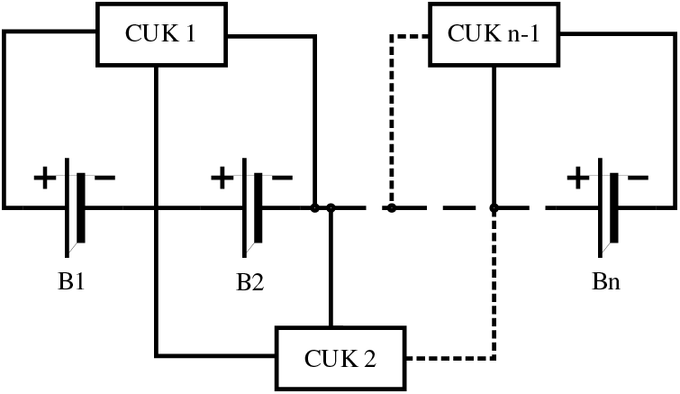
Figure 1: Traditional CUK equalizer
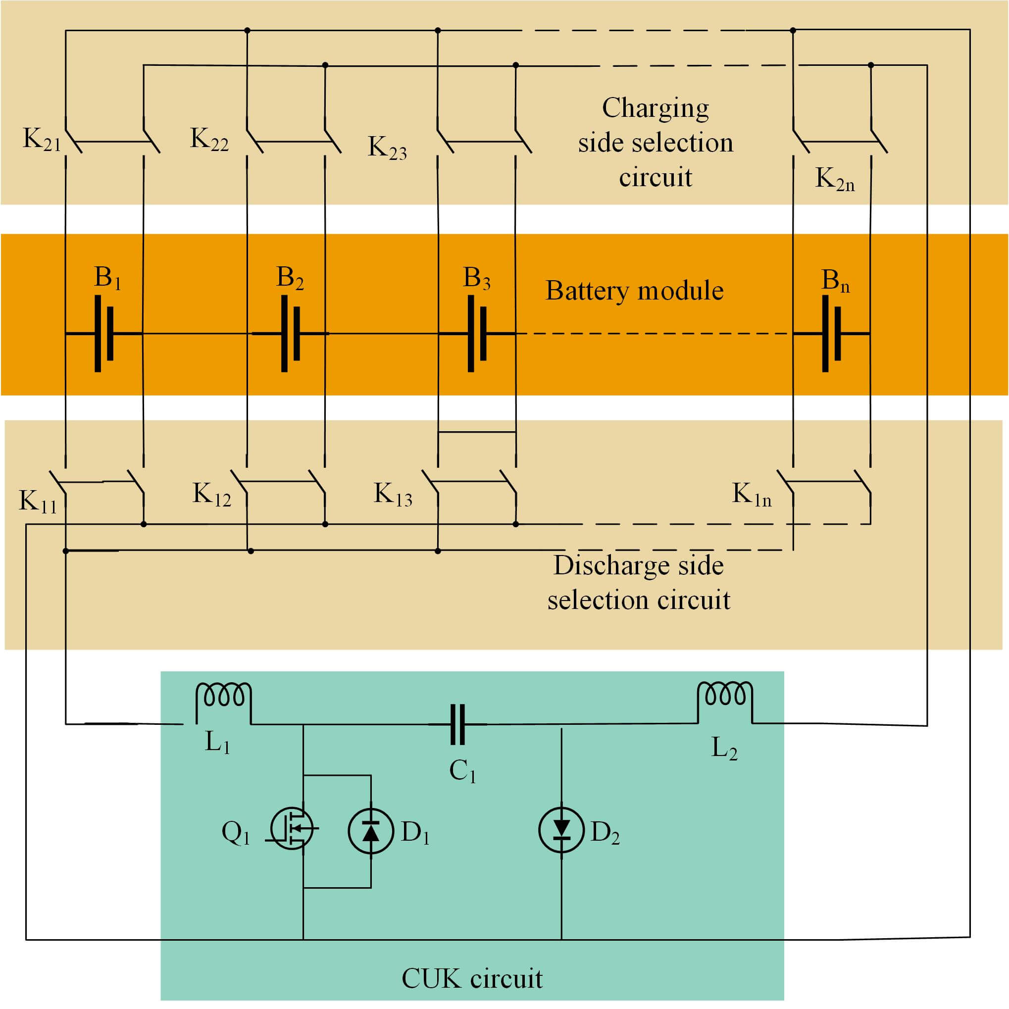
In this paper, an optimized CUK equalization circuit is designed consisting of a battery module, a selection circuit (discharge side and charging side), and a CUK circuit, as shown in Fig. 2. The battery module consists of n cells connected in series. The selection circuit is a switch array of double-layer switches, with switch K1i on the discharge side and switch K2i on the charge side connected to the positive and negative terminals of the battery. The main loop of the equalization topology is the CUK circuit, which is formed by inductors L1 and L2, capacitor C1, diodes D1 and D2, and MOS tube Q1.
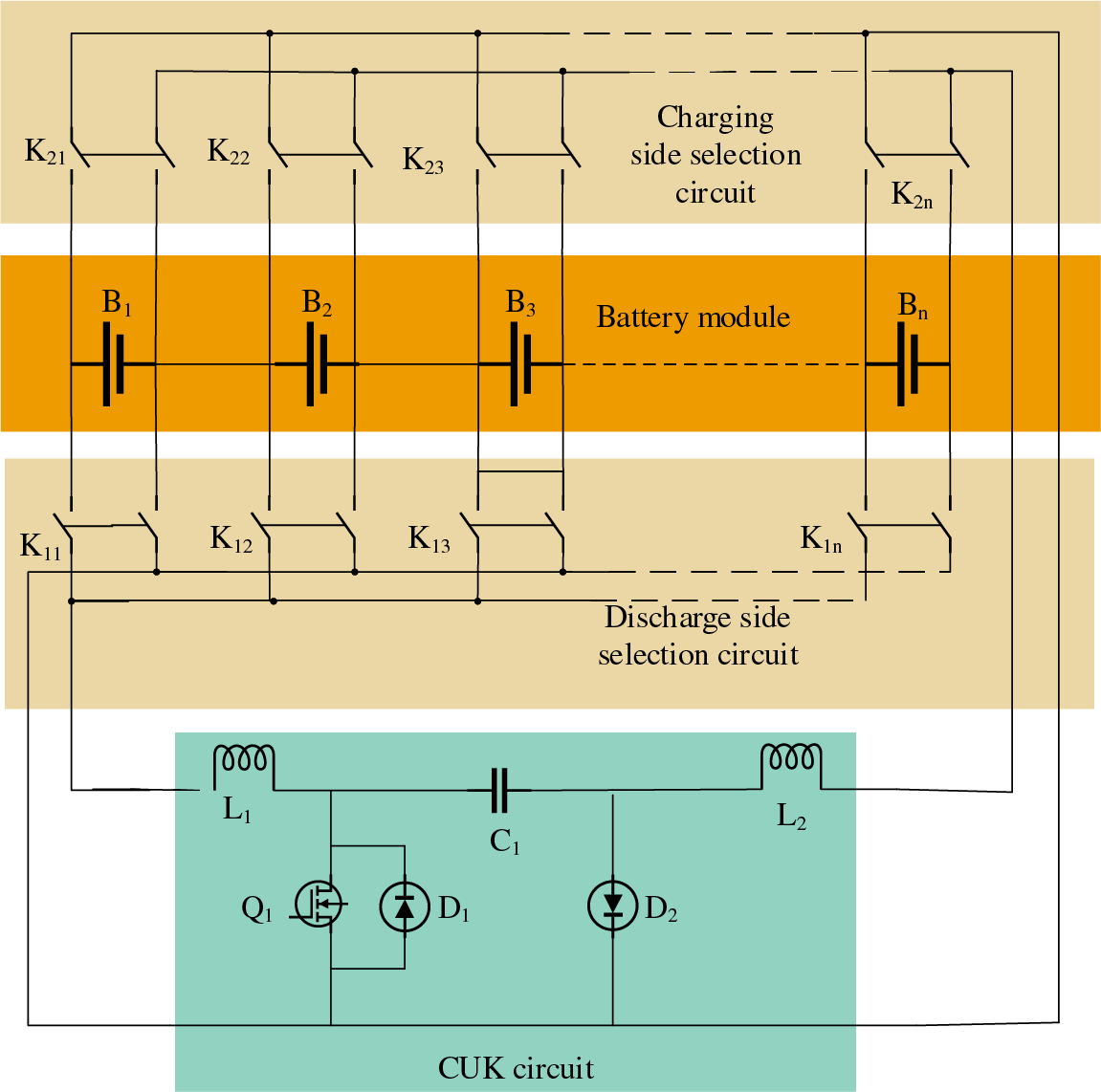
Figure 2: Improved CUK equalization circuit
2.2 Topology and Operational Analysis
The selection circuits of the balanced topology are respectively charging side and discharge side, which are connected to the positive and negative terminals of the battery and the CUK circuit respectively, the switch K1i on the conduction discharge side with high battery energy, the switch K2i on the conduction charging side with low energy, only one switch conducts at a time on the charging and discharging sides.
Taking battery B1 with the highest energy and battery Bn energy as examples, the circuit operating conditions are analyzed. When the energy of battery B1 is the highest, the switch K11 on the discharge side corresponding to battery B1 is turned on, so that it is connected to one end of the CUK circuit, the battery Bn energy is the lowest, and the switch K2n of the charging side of the battery Bn is turned on and connected to the other end of the CUK circuit, and the result is shown in Fig. 3.
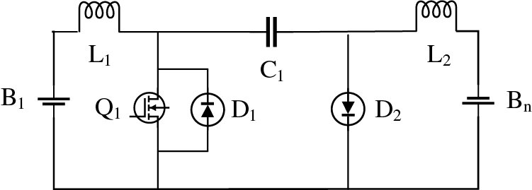
Figure 3: Selecting the completed equalization circuit
The turn-on and turn-off of switch Q1 is controlled by pulse width modulation (PWM). When Q1 is on, battery B1, inductor L1 and switch Q1 form a loop; diode D2 cut off by reverse voltage, and capacitor C1, inductor L1, battery Bn, and switch Q1 form a loop, as shown in Fig. 4. At this time, battery B1 is discharged, inductor L1 is energy storage, and the discharge current is I1; Capacitor C1, switch Q1, battery Bn and inductor L2 form a loop, at this time, capacitor C1 charges battery Bn, inductor L2 stores energy, and the charging current is I2.
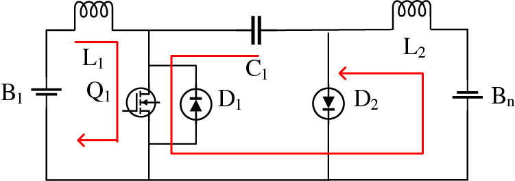
Figure 4: The on-state of the switch Q1
When Q1 is turned off, diode D1 is cut off due to back voltage, and battery B1, inductor L1, capacitor C1 and diode D2 form a loop; The battery Bn, inductor L2 and diode D2 form a loop. This is shown in Fig. 5. At this time, battery B1 and inductor L1 charges capacitor C1 through I1; Inductor L2 charges the battery Bn, the current is I2, and diode D2 acts as a current continuator.
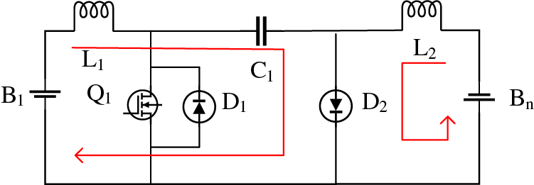
Figure 5: Switch Q1 off state
According to the CUK equalizer circuit design standard, the amplitude of current fluctuations of inductors L1 and L2 should be less than 30% of the average current, see Eqs. (1), (2).
During the conduction of switching tube Q1, it can be deduced from the power relationship that
During the shutdown of the switch Q1, it is available according to the power relationship.
Among them: Vout is the output voltage of the CUK equalizer, D is the duty cycle, and Ts is the switching period.
According to the characteristics of the CUK circuit, the input-output relationship can be obtained (5).
Therefore, the value range of inductors L1 and L2 is
The amplitude of the capacitor voltage fluctuation should be less than 5% of the average value, and the calculation formula of the intermediate storage capacitance C1 is as follows. During DTS < t < TS inductor L1, battery B1, and capacitor C1 form a loop, and this circuit charges capacitor C1, depending on the power relationship:
Therefore, the value range of capacitor C1 is
The inductor average currents IL1, IL2 and capacitor voltage VC are given by Eqs. (11)–(13).
where VC is the voltage of capacitor C1, and VB1 and VBn are the voltages of the batteries connecting the two ends of the CUK circuit, respectively.
In summary, it can be seen that when its switching period, battery voltage, inductor-capacitor parameters and so on are determined, the equalization current is the size of the Q1 control signal is only related to the duty cycle D and period TS.
3 Balanced Control Strategy Design
Equilibrium variables are the basis for the study of equilibrium control strategies, mainly battery open circuit voltage (OVC) and SOC [22]. Reference [23] was based on the battery open-circuit voltage as the starting or ending equilibrium control variable, although the voltage can be measured directly, but when the voltage is in the plateau period, the amplitude of the battery SOC change with voltage is not significant, and the real-time performance of the open-circuit voltage is also insufficient. SOC is the most characteristic of battery power, and it is also a commonly used indicator in equilibrium research. Jiaqiang et al. [24] compared and analyzed the voltage and SOC equalization under the same conditions, and the control effect of the latter is better under the premise that the accurate estimation results of the state of charge can be obtained. Although the SOC needs to be calculated, it can better reflect the current state of the battery and has a good equalization effect. This paper selects variables combining battery voltage and SOC, and uses different control variables at different stages to improve accuracy and reduce control difficulty. When the battery SOC is 20%~80%, SOC is selected as the equilibrium variable; when the battery SOC is 0%~20% and 80%~100%, the battery voltage is selected as the equilibrium variable.
The parameter setting of traditional PID control relies on the accurate control system model, the calculation process is complex, the test process needs to be manually tuned by trial method, relying on debugging experience, and the traditional PID controller is unchanged after the three parameters are set, and does not have adaptive characteristics. Adaptive PID uses online identification to identify changes in system parameters, and then uses the idea of pole configuration to calculate PID parameters to ensure optimal work. In this article, the adaptive PID controller can automatically adapt the equalization current to improve the equalization speed. Compared with fuzzy control, adaptive PID control has simple structure, good robustness and high reliability.
In this paper, the equalization control strategy is to use the adaptive PID control algorithm to adapt the duty cycle of PWM, so as to adjust the equalization current, when the difference between the voltage/SOC of the discharged battery and the rechargeable battery is large, the equalization current should be large, and vice versa.
As shown in Fig. 6, two types of equilibrium variables are considered, but the adaptive PID control is similar, with 2% ε and 10 mV γ. Taking the battery SOC as an example of the equilibrium variable, the battery SOC monitoring module will monitor the SOC in real time, When the battery’s state of charge (SOC) is between 20% and 80%, the equalization circuit will connect the maximum battery SOC to the discharge side through the selection circuit, and the smallest battery SOC is connected to the charging end. The absolute value ΔSOC of the difference between the average SOCave of the SOCs of the two cells participating in the equalization and the SOCi of one of the cells participating in the equalization is used as the input of the adaptive PID, see Eqs. (14), (15), and its output can obtain the duty cycle of the PWM wave, thereby controlling the conduction and turn-off of the switch to achieve the effect of controlling the equalization current, with voltage as the equilibrium variable.
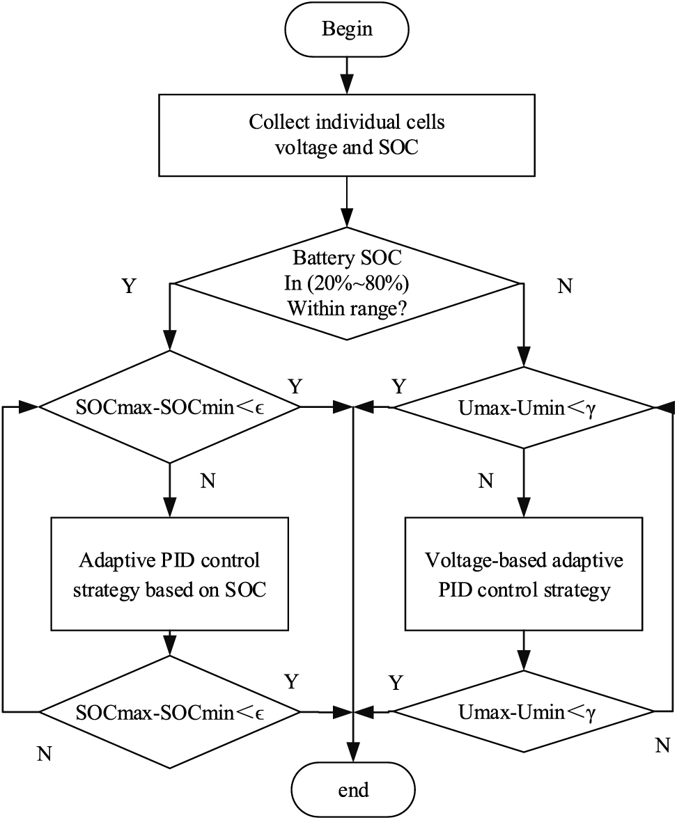
Figure 6: Balancing flow chart of lithium-ion battery pack based on CUK converter
In Eqs. (14), (15), SOCi and SOCj represent two cells participating in equalization.
4 Designing Simulation Platforms and Conducting Experimental Analyses
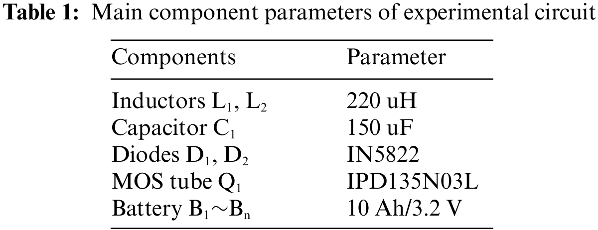
In this paper, the simulation experiment uses Matlab/Simulink2020b for simulation modeling, The lithium-ion battery parameters are 3.7 V/2.2 AH, with an initial SOC value for each individual cell. of the battery module are 78%, 74%, 70%, 66%, 62% and 58%, respectively. The equalization simulation model includes a battery module, a selection circuit, a CUK equalizer, a select circuit switch control module, and an adaptive PID-based current control module. Battery module, selection circuit, CUK equalizer are explained in Section 2.1; the selection circuit switch control module is based on the state of each battery in the battery module to achieve the switch on and off; the current control module, which is based on an adaptive PID, is implemented as a Matlab function. To validate the effectiveness of the proposed topology and algorithm in this paper, both the PID control module and the PWM output module are utilized. the following will be respectively the comparative experiment of balanced topology and adaptive PID control. The main parameters of the experimental circuit are shown in Table 1.
4.1 Validation of Topology Performance
The study aims to confirm the effectiveness and superiority of the new CUK equalizer over the traditional CUK equalizer. A comparison experiment is designed to assess the equalization time needed for both topologies in stationary equalization. This will provide evidence of the new CUK equalizer’s superiority.
Figs. 7 and 8 show the SOC curves of each cell in static equalization of the traditional CUK equalizer and the new CUK equalizer proposed in this paper, respectively.
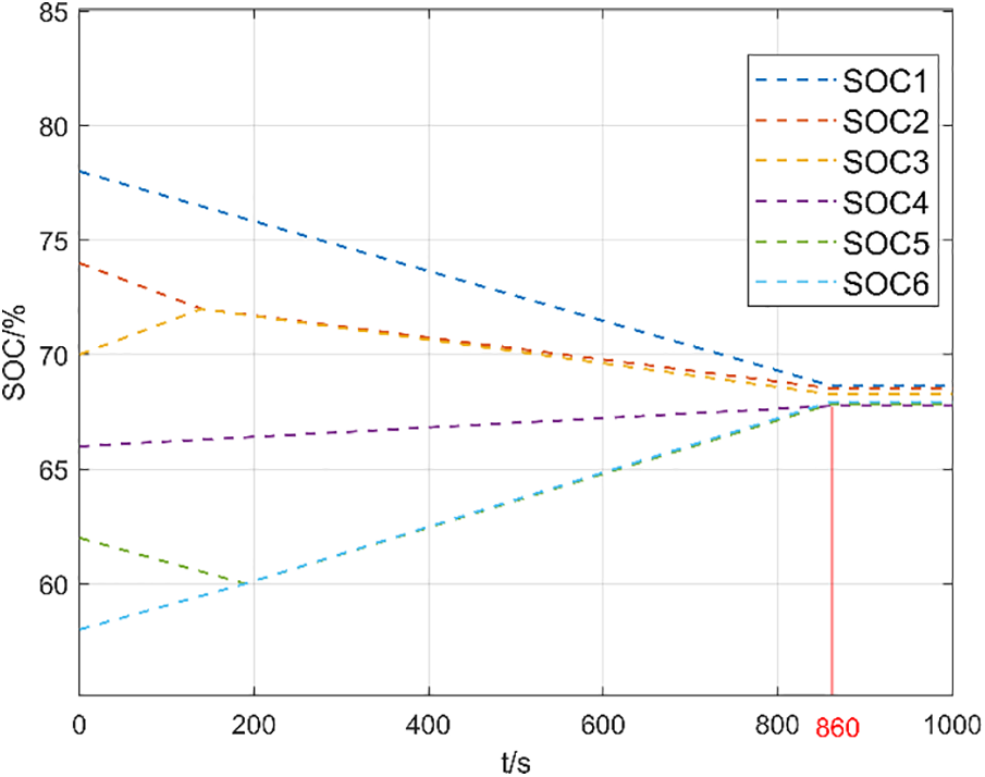
Figure 7: Traditional CUK static equilibrium
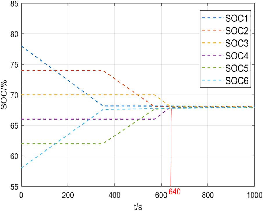
Figure 8: Novel CUK static equilibrium
Figs. 7 and 8 demonstrate that the traditional CUK equalizer takes approximately 860 s to complete equalization in a static state. In contrast, the new CUK equalizer proposed in this paper only takes 640 s to complete the same task, resulting in a 25.58% reduction in equalization time. These results confirm the effectiveness and superiority of the new CUK equalizer proposed in this study.
Compared with the traditional CUK equalizer, the topology in this paper uses double-layer switches as the selection circuit, despite the large number of switches, it is possible to reduce the number of capacitive inductors, but the control is simple, the stability is strong, and the structural complexity of the topology will not increase exponentially when the number of batteries increases.
4.2 Adaptive PID Superiority Verification
In this paper, in order to validate the superiority of the adaptive PID control algorithm used, comparative experiments are carried out under three working conditions: stationing, charging and discharging, and the mean difference method is used for the comparative experiments. In this scenario, both the charge equalization test and the discharge equalization test employ constant current for charging and discharging static equalization.
Figs. 9 and 10 are based on the mean value difference (MVD). method based on the static equilibrium cell SOC curve and the static equilibrium cell SOC curve based on adaptive PID.
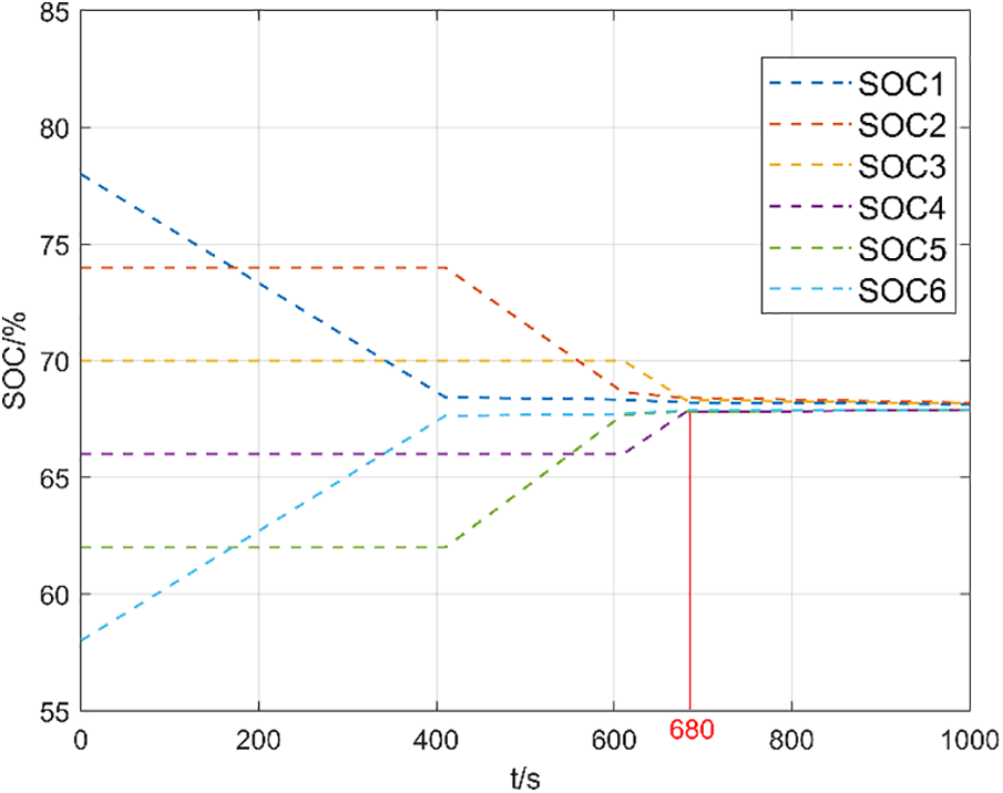
Figure 9: Stationary equilibrium based on mean difference method
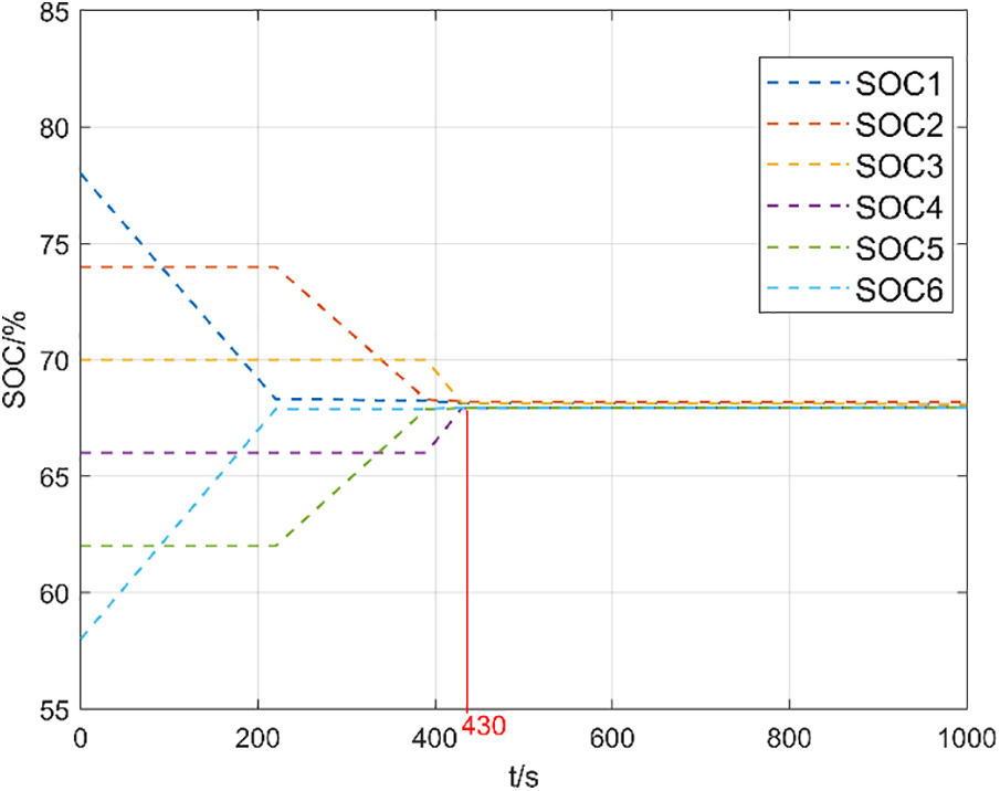
Figure 10: Static equalization based on adaptive PID
From Figs. 9 and 10, it can be observed that under the static equalization experimental conditions, it takes approximately 680 s to complete the equalization using the mean-value difference method, whereas it only takes 430 s to complete the equalization using adaptive PID control, resulting in a 36.76% improvement in equalization speed. This verifies the superiority of adaptive PID control over the mean-value difference method in static equalization.
a. Charge equalization
Figs. 11 and 12 are the SOC curves of each cell of charge balancing based on the MVD method and the SOC curve of each cell of each cell based on adaptive PID, respectively.
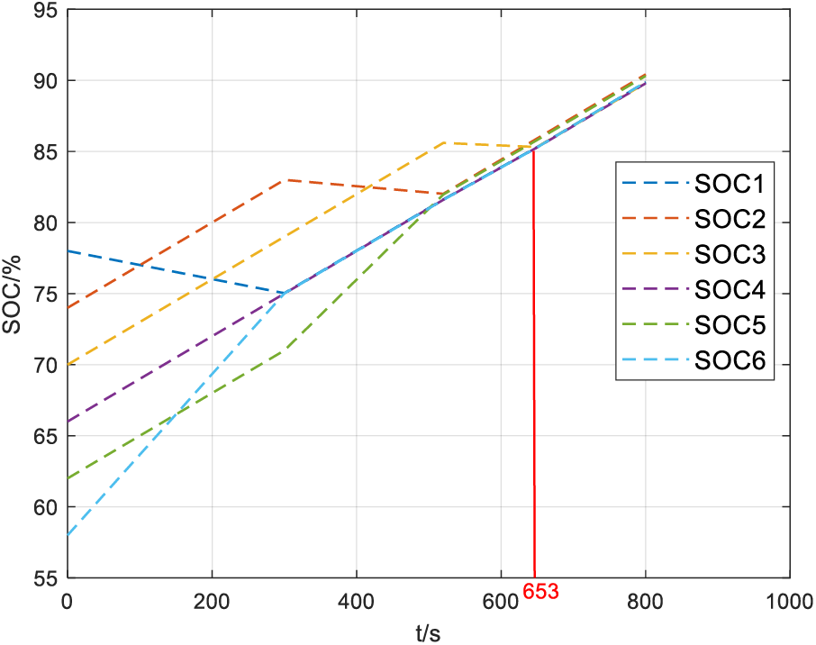
Figure 11: Charge equalization based on the mean difference method
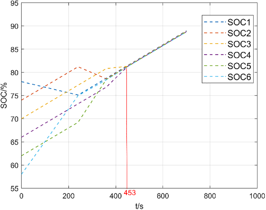
Figure 12: Charge equalization based on adaptive PID
From Figs. 11 and 12, it is evident that in the charging equalization experiment, it takes approximately 653 s to complete the equalization using the mean-value difference method, whereas it only takes 453 s to complete the equalization using the adaptive PID. The equalization speed is improved by about 30.62%, confirming the superiority of the adaptive PID control over the mean-value difference in the charging equalization.
b. Discharge equalization
Figs. 13 and 14 are respectively the SOC curve of each cell with emission equalization based on the MVD method and the SOC curve of each cell with emission equalization based on adaptive PID.
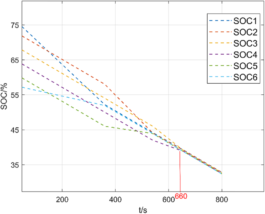
Figure 13: Discharge equilibrium based on the mean difference method
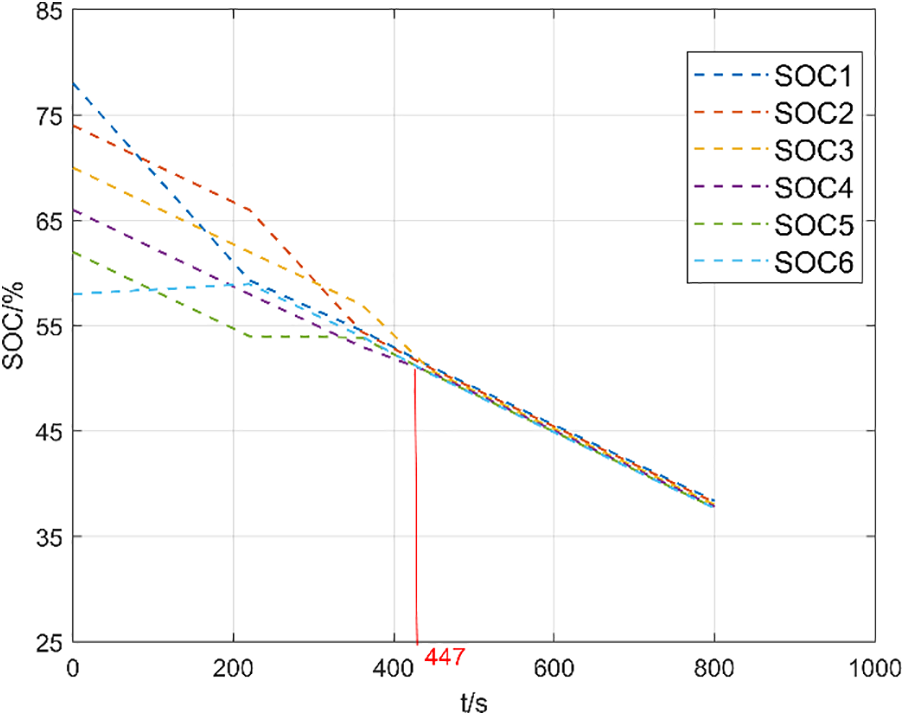
Figure 14: Discharge equalization based on adaptive PID
From Figs. 13 and 14, we can observe that in the discharge equalization process, it takes approximately 660 s to complete the equalization using the mean-value difference method, and about 447 s to complete the equalization with adaptive PID. This results in an improvement in equalization speed of about 28.78%. This experiment confirms the superiority of the adaptive PID control over the mean-value difference method in discharge equalization.
The SOC and SOC ranges of each single cell after the completion of the standing experiment, charging experiment and discharge experiment are shown in Table 2.
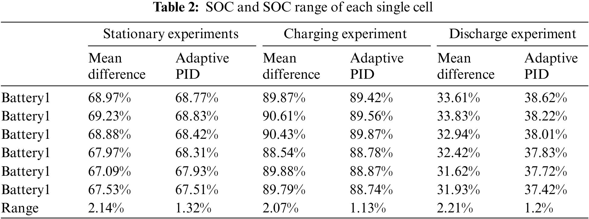
In Table 2, it is evident that the polar deviation of each individual cell is smaller when using the adaptive PID control method compared to the mean-value difference method in static equalization, charging equalization, and discharging equalization experiments. Therefore, the equalization effect is better when based on adaptive PID control.
From Figs. 9–14 and the data analysis in Table 2, it is evident that the adaptive PID algorithm’s effectiveness lies in its ability to dynamically adjust the equilibrium current and enhance the equilibrium speed in static, charging, and discharging experiments.
Aiming at some problems of the traditional CUK equalizer in the equalization process, this paper carries out some optimization of the CUK equalizer, which can realize the equalization between any two batteries, shorten the equalization path and improve the efficiency. In terms of equalization variable selection, battery voltage and battery SOC are used as composite equalization variables, and SOC is used as the equalization variable in the voltage plateau period, while battery voltage is used as the equalization variable in other periods. Adaptive PID control strategy is used to generate adaptive equalization current, shorten the equalization time and improve the equalization efficiency. The effectiveness of the optimized topology in this paper is experimentally verified.
Acknowledgement: I would like to thank Professor Yu Zhang for her careful guidance and the encouragement of all colleagues, and Professor Tiezhou Wu for the support of the project fund.
Funding Statement: Natural Science Foundation of China (51677058), Scientific Research Program of Hubei Provincial Department of Education (T2021005).
Author Contributions: The authors confirm that their contributions to the paper are as follows: research conception and design: Sheng Tian, Yongkang Zhang; data collection: Sheng Tian analysis and interpretation of results: Sheng Tian, Yongkang Zhang. draft manuscript preparation: Sheng Tian, Yu Zhang. All authors reviewed the results and approved the final version of the manuscript.
Availability of Data and Materials: The data that support the findings of this study are available from the corresponding author upon reasonable request.
Conflicts of Interest: The authors declare that they have no conflicts of interest to report regarding the present study.
References
1. Pan, J. W., Chen, X. F., Luo, X. N., Zeng, X. S., Liu, Z. H. (2022). Analysis of the impact of China’s energy industry on social development from the perspective of low-carbon policy. Energy Reports, 8, 14–27. [Google Scholar]
2. Fragkos, P., Dalla Longa, F., Nogueira, L. P., Vander Zwaan, B. (2022). System-level effects of increased energy efficiency in global low-carbon scenarios: A model comparison. Computers & Industrial Engineering, 167, 108029. 10.1016/j.cie.2022.108029 [Google Scholar] [CrossRef]
3. Zhang, W., Zhang, M., Wu, G. (2022). How to realize low-carbon travel in rural areas? Evidence from China. Transportation Research Part D: Transport and Environment, 105, 103224. 10.1016/j.trd.2022.103224 [Google Scholar] [CrossRef]
4. Murugan, M., Saravanan, A., Elumalai, P. V., Murali, G., Dhineshbahu, N. R. (2022). Thermal management system of lithium-ion battery packs for electric vehicles: An insight based on bibliometric study. Journal of Energy Storage, 52, 104723. 10.1016/j.est.2022.104723 [Google Scholar] [CrossRef]
5. Murali, G., Sravya G.S., N., Jaya, J., Naga Vamsi, V. (2021). A review on hybrid thermal management of battery packs and it’s cooling performance by enhanced PCM. Renewable and Sustainable Energy Reviews, 150, 111513. 10.1016/j.rser.2021.111513 [Google Scholar] [CrossRef]
6. Tian, H. X., Qin, P. L., Li, K., Zhao, Z. (2020). A review of the state of health for lithium-ion batteries: Research status and suggestions. Journal of Cleaner Production, 261, 120813. 10.1016/j.jclepro.2020.120813 [Google Scholar] [CrossRef]
7. Juqu, T., Willenberg, S. C., Pokpas, K. (2022). Advances in paper-based battery research for biodegradable energy storage. Advanced Sensor and Energy Materials, 1(4), 100037. 10.1016/j.asems.2022.100037 [Google Scholar] [CrossRef]
8. Li, Z., Yang, Y., Wang, J., Yang, Z., Zhao, H. (2022). Sandwich-like structure C/SiOx@graphene anode material with high electrochemical performance for lithium-ion batteries. International Journal of Minerals, Metallurgy and Materials, 29(11), 1947–1953. 10.1007/s12613-022-2526-0 [Google Scholar] [CrossRef]
9. Zhang, S., Yang, G., Li, X., Li, Y., Wang, Z. (2022). Electrolyte and current collector designs for stable lithium metal anodes. International Journal of Minerals, Metallurgy and Materials, 29(5), 953–964. 10.1007/s12613-022-2442-3 [Google Scholar] [CrossRef]
10. Ye, Y. M., Wang, J. P., Wang, X. L. (2023). A multi-winding transformer-based active cell equalizer with self-driven switches for series-connected lithium-ion batteries and super-capacitors. Journal of Energy Storage, 70, 107971. 10.1016/j.est.2023.107971 [Google Scholar] [CrossRef]
11. Zhou, L., Zheng, Y. J., Ouyang, M. G., Lu, L. G. (2017). A study on parameter variation effects on battery packs for electric vehicles. Journal of Power Sources, 364, 242–252. 10.1016/j.jpowsour.2017.08.033 [Google Scholar] [CrossRef]
12. Wang, Y. H., Huang, H. H., Wang, H. X. (2023). Rapid-regroup strategy for retired batteries based on short-time dynamic voltage and electrochemical impedance spectroscopy. Journal of Energy Storage, 63, 107102. 10.1016/j.est.2023.107102 [Google Scholar] [CrossRef]
13. Wang, Y. X., Zhong, H., Li, J. W., Zhang, W. (2022). Adaptive estimation-based hierarchical model predictive control methodology for battery active equalization topologies: Part I-Balancing strategy. Journal of Energy Storage, 45, 103235. 10.1016/j.est.2021.103235 [Google Scholar] [CrossRef]
14. Turksoy, A., Teke, A., Alkaya, A. (2020). A comprehensive overview of the dc-dc converter-based battery charge balancing methods in electric vehicles. Renewable and Sustainable Energy Reviews, 133, 110274, 2020. 10.1016/j.rser.2020.110274 [Google Scholar] [CrossRef]
15. Ghaeminezhad, N., Ouyang, Q., Hu, X. S., Xu, G. T., Wang, Z. S. (2021). Active cell equalization topologies analysis for battery packs: A systematic review. IEEE Transactions on Power Electronics, 36(8), 9119–9135, 2021. 10.1109/TPEL.2021.3052163 [Google Scholar] [CrossRef]
16. Ye, Y., Jiang, J., Zhao, E. (2023). An improved balancing strategy for inductor-based balancing circuit. International Conference on Power Science and Technology (ICPST), pp. 387–391. Kunming, China, IEEE. [Google Scholar]
17. Wu, J., Zheng, W., Jiang, Y. (2021). Dynamic equalization control of battery pack based on switched capacitance method. International Conference on Advanced Technology of Electrical Engineering and Energy (ATEEE), pp. 56–56. Qingdao, China, IEEE. [Google Scholar]
18. Qian, T., Yang, Y. F., Zhao, W. R. (2023). A boost-type three-port resonant forward converter with flexible power flow path optimization for PV systems. IEEE Transactions on Circuits and Systems II: Express Briefs, 70(1), 161–165. [Google Scholar]
19. Cao, J. W., Xia, B. Z., Zhou, J. (2021). An active equalization method for lithium-ion batteries based on flyback transformer and variable step size generalized predictive control. Energies, 14(1), 207. 10.3390/en14010207 [Google Scholar] [CrossRef]
20. Zhang, Y., Yang, R. (2021). An improved buck-boost circuit equalization method for series connected battery packs. IEEE 4th International Electrical and Energy Conference (CIEEC), pp. 1–6. Wuhan, China, IEEE. [Google Scholar]
21. Dam, S. K., John, V. (2021). Low-frequency selection switch based cell-to-cell battery voltage equalizer with reduced switch count. IEEE Transactions on Industry Applications, 57(4), 3842–3851. 10.1109/TIA.2021.3075184 [Google Scholar] [CrossRef]
22. Li, R., Liu, P. D., Li, K. X., Zhang, X. Y. (2023). Research on retired battery equalization system based on multi-objective adaptive fuzzy control algorithm. IEEE Access, 11, 89535–89549. 10.1109/ACCESS.2023.3306784 [Google Scholar] [CrossRef]
23. Li, L. R., Huang, Z. W., Li, H., Peng, J. (2017). A rapid cell voltage balancing scheme for supercapacitor based energy storage systems for urban rail vehicles. Electric Power Systems Research, 142, 329–340. 10.1016/j.epsr.2016.09.021 [Google Scholar] [CrossRef]
24. E, J. Q., Zhang, B., Zeng, Y., Wen, M., Wei, K. X. (2022). Effects analysis on active equalization control of lithium-ion batteries based on intelligent estimation of the state-of-charge. Energy, 238, 121822. 10.1016/j.energy.2021.121822 [Google Scholar] [CrossRef]
Cite This Article
 Copyright © 2024 The Author(s). Published by Tech Science Press.
This work is licensed under a Creative Commons Attribution 4.0 International License , which permits unrestricted use, distribution, and reproduction in any medium, provided the original work is properly cited.
 Downloads
 Citation Tools