 Open Access
ARTICLE
Research on Grid-Connected Control Strategy of Distributed Generator Based on Improved Linear Active Disturbance Rejection Control
School of Automation and Electrical Engineering, Lanzhou Jiaotong University, Lanzhou, 730070, China
* Corresponding Author: Xin Mao. Email:
Energy Engineering 2024, 121(12), 3929-3951. https://doi.org/10.32604/ee.2024.057106
Received 08 August 2024; Accepted 25 September 2024; Issue published 22 November 2024
Abstract
The virtual synchronous generator (VSG) technology has been proposed to address the problem of system frequency and active power oscillation caused by grid-connected new energy power sources. However, the traditional voltage-current double-closed-loop control used in VSG has the disadvantages of poor disturbance immunity and insufficient dynamic response. In light of the issues above, a virtual synchronous generator voltage outer-loop control strategy based on improved linear autonomous disturbance rejection control (ILADRC) is put forth for consideration. Firstly, an improved first-order linear self-immunity control structure is established for the characteristics of the voltage outer loop; then, the effects of two key control parameters-observer bandwidth ω0 and controller bandwidth ωc on the control system are analyzed, and the key parameters of ILADRC are optimally tuned online using improved gray wolf optimizer-radial basis function (IGWO-RBF) neural network. A simulation model is developed using MATLAB to simulate, analyze, and compare the method introduced in this paper. Simulations are performed with the traditional control strategy for comparison, and the results demonstrate that the proposed control method offers superior anti-interference performance. It effectively addresses power and frequency oscillation issues and enhances the stability of the VSG during grid-connected operation.Keywords
The advent of novel energy sources, including solar and wind power, has precipitated a surge in the prevalence and severity of frequency and power instability issues associated with distributed power supply access to the grid. Since the distributed power supply is realized through the control system composed of power electronic devices to be connected to the grid, it will inevitably introduce the problems of poor anti-interference performance and low reliability that exist in the power electronic devices themselves. To improve the reliability of power supply and reduce the impact of distributed power grid connections on the overall grid, Virtual Synchronous Generator (VSG) technology has been proposed and extensively implemented in the grid-connection control of distributed power [1,2]. The VSG technology reduces the frequency and active power oscillations by providing the virtual inertia and virtual damping required by the system, making it possible for the distributed power supply to be connected to the grid, which leads to the improvement of the undesirable effects caused by the grid-connection of distributed power sources, and improves the power quality and system stability [3].
At present, a large amount of literature has conducted in-depth research on VSG technology. Yang et al. proposed a transient stability enhancement method based on the transient stability and frequency stability of VSG in [4]. The stability of VSG is improved by optimizing the damping ratio, but due to the complexity of the power grid environment, especially when multiple VSG are involved in parallel operation, it may be difficult to adjust parameters and the robustness of the control strategy. Wang et al. proposed to apply droop control and neural network to VSG control in [5], realizing dynamic adjustment of key parameters in VSG, and completing initial value determination of key parameters rotational inertia and damping coefficient through small signal modeling analysis, but did not analyze the applicability of the proposed strategy under fault conditions. Ren et al. proposed a power decoupling strategy for virtual synchronous generators to solve the power coupling problem and enhance the system response in [6], aiming at the frequency deviation and dynamic oscillation caused by the interaction of active power and reactive power. However, implementing this strategy can complicate system control, especially when the virtual impedance is dynamically adjusted in real applications. Ling et al. all proposed a VSG parameter adaptive control strategy based on RBF neural network in [7–9]. Through online dynamic tuning of rotational inertia and damping coefficient, optimal parameters are found, and various fluctuations of the system are adjusted in real-time, which can make the system stable in a short time. However, they did not consider the shortcomings of the RBF neural network itself and did not optimize the RBF neural network.
In the VSG technology discussed earlier, the typical approach is the traditional voltage-current double closed-loop control, which relies on the core principle of proportional-integral (PI) control. However, PI control has limitations, including slow dynamic response, weak anti-interference capability, and phase lag. To overcome these issues, Active Disturbance Rejection Control (ADRC) proposed by Prof. Jingqing Han has been implemented in VSG technology to replace the original PI control due to its robust anti-interference characteristics and improved dynamic response capabilities. Nonetheless, the parameter configuration of ADRC is noted to be more complex and challenging for practical engineering applications. Building on this, the LADRC scheme introduced by Prof. Gao simplifies the parameter determination process, optimizing it from the original multi-parameter determination to focusing on only three key parameters [10]. Liu et al. proposed to combine the control structure and control principle of LADRC with VSG control from the perspective of power regulation optimization and frequency regulation optimization in [11–13]. This approach enhances the VSG system’s dynamic response and increases its robustness. However, the parameter selection and adjustment of LADRC have not been studied in depth. Lin et al. proposed to improve the voltage-current double closed loop from the voltage outer loop of the VSG control system by using LADRC in [14,15]. This approach enhances the system’s anti-interference capability and accelerates its response time, but the problem of how to determine the key parameters of LADRC has not been further discussed and studied. Liu et al. proposed to tune the key parameters of LADRC through the neural network in [16–17]. This method makes it easier to determine parameters and speeds up the dynamic response ability of the system, but it does not optimize the basic algorithm.
In light of the findings of the aforementioned studies, this paper proposes a redesign of the voltage outer loop of the VSG based on the Improved Linear Active Disturbance Rejection Control (ILADRC) methodology. This approach is expected to enhance the system’s anti-interference capability and response speed. Firstly, in Section 2, a simulation system is constructed for the research object of this paper, which includes a photovoltaic hybrid energy storage system in the front stage and a VSG inverter system in the backstage. Secondly, in Section 3, an enhanced first-order LADRC control methodology is presented for the conventional LADRC, which is employed in the voltage-current dual closed-loop control in VSG. The stability of this methodology is demonstrated, and the selection of the three pivotal parameters of ILADRC is examined. In the final section, a comparative analysis is conducted using the MATLAB simulation tool to evaluate the proposed strategy under different operating conditions. The objective is to demonstrate that the strategy has superior anti-interference performance, which in turn enhances system stability.
2 System Structure and Basic Principles
2.1 Introduction to Photovoltaic Hybrid Energy Storage System
This article uses the photovoltaic hybrid energy storage system as a model to build distributed power. Fig. 1 shows the structure of a photovoltaic (PV) hybrid energy storage system, including three parts: the PV array, the battery, and the supercapacitor. Among them, the PV array adopts the maximum power point tracking technology, which outputs a stable direct current (DC) bus voltage through a Boost converter. The battery and supercapacitor are connected to the DC bus through a Bidirectional Buck-Boost converter. The hybrid energy storage system composed of batteries and supercapacitors can significantly solve the intermittent and random problems of photovoltaic power generation systems, maintain a constant DC bus voltage, and play a significant role in ensuring the stability of distributed grid integration.
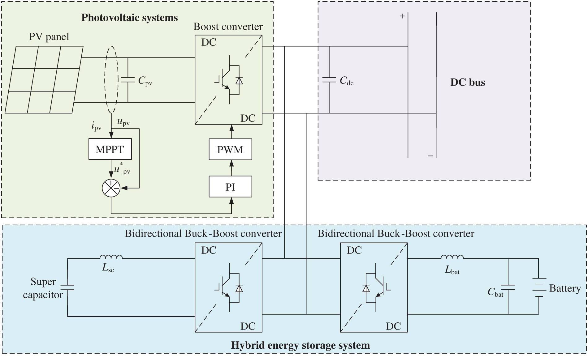
Figure 1: Photovoltaic hybrid energy storage system
The working principle of the PV hybrid energy storage system is described as follows: when the PV array sends out excess power, the excess power will be supplied to the supercapacitor and battery for charging; when the PV array sends out power with a shortfall, at this time by the supercapacitor and battery for discharging, to provide the power shortfall, which the supercapacitor to provide the high-frequency component of power, the battery to provide the low-frequency component of power. The access of a hybrid energy storage system can realize the secondary frequency regulation function when the distributed power supply operates on an island; it can promptly regulate voltage and frequency fluctuations in the power grid, ensuring stable operation during grid connection.
2.2 Mathematical Modeling of VSG Control
VSG technology is based on the mathematical model of a synchronous generator, and through the control algorithm, it makes the inverter have the external characteristics equivalent to the synchronous generator, thus realizing the function of system voltage and frequency regulation and improving system stability. The schematic diagram of the VSG main circuit of the grid-connected inverter and the associated control strategy are given in Fig. 2.
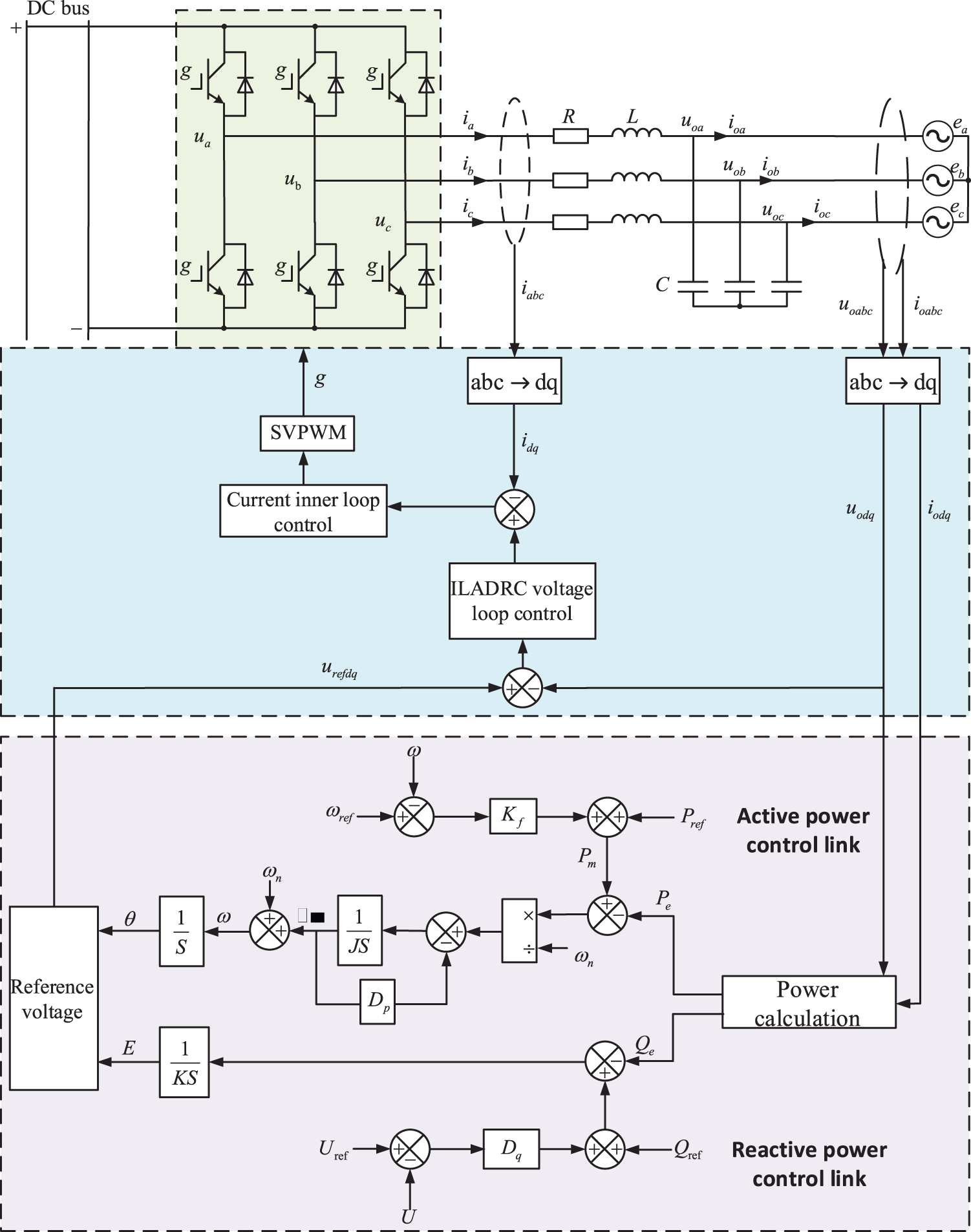
Figure 2: Overall schematic diagram of VSG control structure
The DC bus voltage output from the distributed PV hybrid energy storage system in Fig. 1 is connected to the grid-connected inverter, and then the voltage and current output from the inverter side are connected to the grid through the LC filter circuit.
where
A transformation of the park in Eq. (1) yields the voltage and current expressions in the dq coordinate system:
The active and reactive instantaneous power of the VSG controller can be obtained from the above equation:
The equation of state can be obtained from Eq. (2):
2.3 Basic Principles of VSG Control
The core links of the VSG are the active-frequency control link and the reactive voltage control link, respectively. Among them, the active-frequency control link refers to the rotor equations of motion of the synchronous generator and adds the active sag link, whose control block diagram is shown in Fig. 2, and the rotor mechanical equations of VSG is:
where
By referring to the excitation system of the synchronous generator, the control method of the reactive-voltage module of VSG can be obtained. Using the reactive-voltage sag characteristic curve of the synchronous generator, the reactive-voltage control equation of the virtual synchronous generator is as follows:
where
3 Improved Linear Active Disturbance Rejection Control Technology
3.1 The Basic Principle of LADRC
LADRC mainly consists of two components: a linear extended state observer (LESO) and linear state error feedback (LSEF). Among them, LESO is the core of LADRC, and its main role is to estimate the total target state and total system interference. LSEF achieves tracking compensation of the total system disturbance by tracking the error signal of the input signal, and the PD controller is usually used as the LSEF for the second-order LADRC, and the simple P controller is selected for the first-order LADRC. The basic structure of a traditional second-order LADRC is shown in Fig. 3.
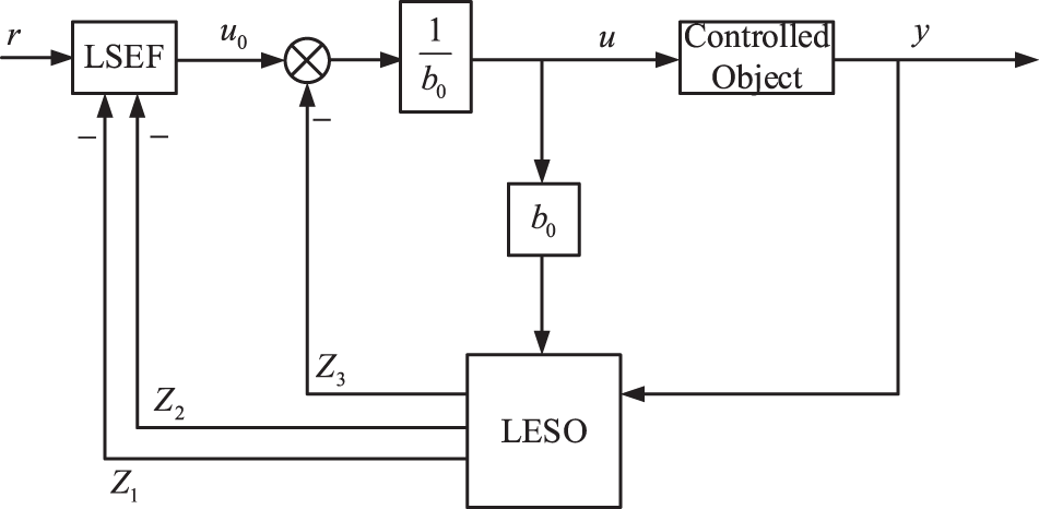
Figure 3: Basic structure of traditional second-order LADRC
As shown in Eq. (4), the mathematical expression of the object of study in this article is a first-order function. Consequently, the order of LADRC is selected as the first order. Given the symmetry of the mathematical model of the dq axis, this paper employs the d-axis as a case study for analysis. A generalized expression can be employed to represent the control object of LADRC as follows:
where
The state space expression is:
The second order LESO of LADRC is designed as follows:
where
Let
LESF is designed to:
where
Let the controller bandwidth
The bandwidth gain of the LESO is obtained from the above equation:
From the above analysis, it can be seen that the key parameters of the LADRC are
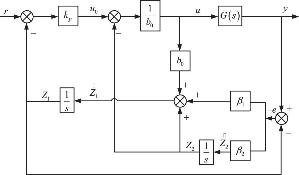
Figure 4: First-order LADRC control block diagram
3.2 ILADRC Design and Performance Analysis
In the traditional first-order LADRC, the fundamental aspect of the LESO is its capacity to meticulously observe and accurately quantify the total disturbances emanating from both internal and external sources, and subsequently, to implement precise compensatory measures. Therefore, to improve the observation accuracy of the LESO, the principle of deviation control is utilized to improve LESO so that it can converge quickly to obtain improved linear active disturbance rejection control (ILADRC) [18]. The LESO is rewritten from Eq. (12):
Organizing the above equation yields:
From the above equation, the deviations of
Rewriting the improved LESO matrix:
From the above equations, Fig. 5 shows the control block diagram of ILADRC.
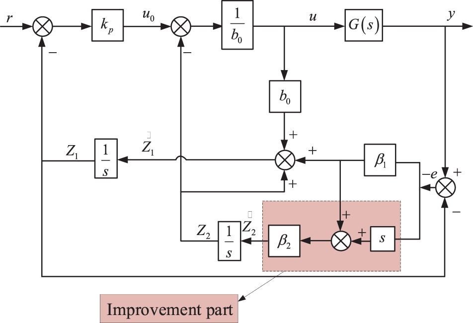
Figure 5: ILADRC control block diagram
Re-performing the pole configuration for the improved observer yields the improved observer characteristic equation as:
The bandwidth gain of the improved LESO is obtained from the above equation:
The error analysis is performed for the above proposed ILADRC and the transfer function is obtained from Eq. (20):
Let
For analysis, taking
From Eq. (25), it is evident that the improved LADRC shows strong convergence performance.
In the following, the traditional LESO is analyzed in comparison with the improved LESO (ILESO), and the transfer function of the traditional LESO is obtained from Eq. (11):
Comparing and analyzing Eq. (23) with Eq. (26), it is apparent that the difference between the ILESO and the conventional LESO is mainly in
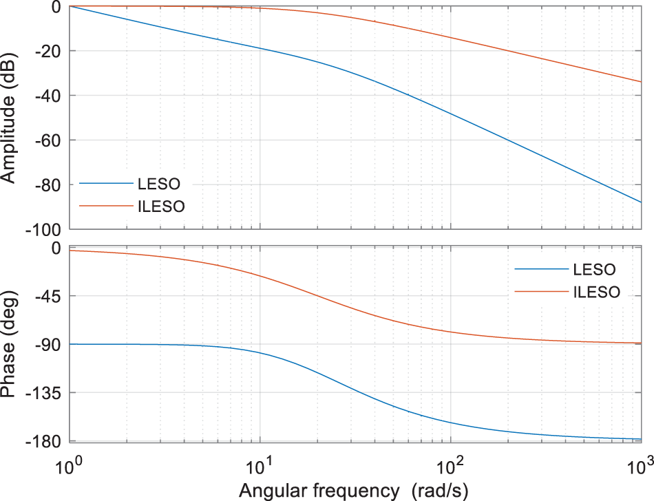
Figure 6: LESO and ILESO frequency characteristics comparison curve
The impact of bandwidth on system performance is examined in the following section, and the transfer function between the state variable
To obtain the Bode plot, the observer bandwidth of the aforementioned equation should be set to the values of 10, 20, 40, and 80, respectively. The resulting plot is illustrated in Fig. 7. As the observer bandwidth increases, the cutoff frequency rises, enabling the system to more accurately assess the error across a broader frequency spectrum and to enhance the tracking performance of
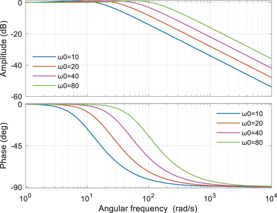
Figure 7: Frequency characteristic curve of T1 (s)
The expression formula of the state variable
For the observer bandwidth of the above equation take the values of 10, 20, 40, and 80, respectively, as illustrated in Fig. 8, the Bode plot can be generated. It is noticed that as the
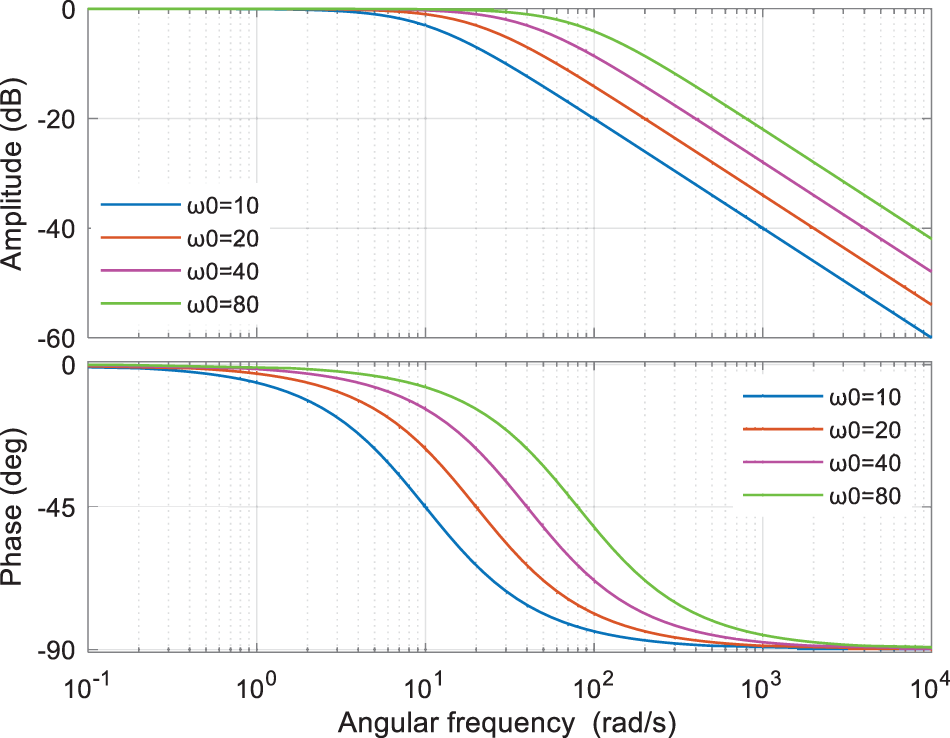
Figure 8: Frequency characteristic curve of T2 (s)
From Eq. (13):
The above equation is obtained by substituting Eq. (23) after applying the Rasch transformation:
where
From Eq. (10):
Substituting Eqs. (30)–(32) into Eq. (33) yields:
where
The formula
Analyzing the above equation, it can be seen that it is connected to both the controller bandwidth
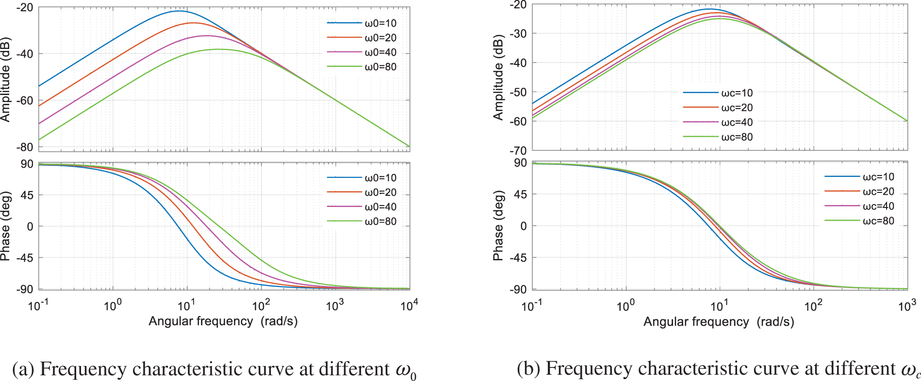
Figure 9: Frequency characteristic curve of T3 (s)
From Fig. 9, it can be seen that with the increase of
3.3 A demonstration of Voltage Outer Loop Design and Stability Based on ILADRC Approach
The conventional voltage-current double closed-loop control uses PI control to eliminate system errors and disturbances through the integral link, but there are certain defects in this control method, the tracking performance for disturbances is not good enough, the dynamic response is not fast enough, and when a large disturbance occurs in the system, there will be a large overshoot of the active and the frequency, which will affect the grid-connected performance of distributed power supply. Because of the above defects, this text proposes to use the improved linear self-immunity control with strong anti-interference performance for the voltage outer loop design, and the current inner loop still adopts PI control, whose control structure is shown in Fig. 10.
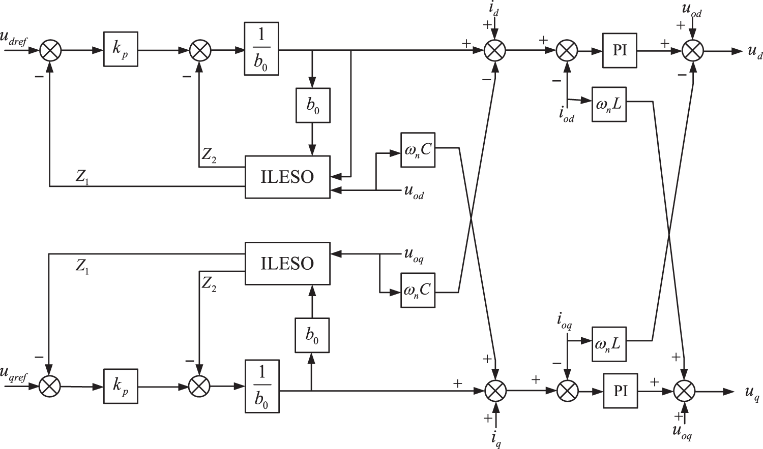
Figure 10: Voltage and current double closed-loop control structure based on ILADRC
From Fig. 10, the output of the voltage outer loop is the input of the current inner loop, which is the current reference value, and the current inner loop part is the controlled object of ILADRC. Referring to References [19] and [20], the current inner loop can be equated to the transfer function shown in Eq. (38):
The block diagram of the closed-loop transfer function of the ILADRC-based voltage outer-loop control system is shown in Fig. 11.

Figure 11: Closed loop control system block diagram
The closed-loop transfer function expression can be obtained from the block diagram of the closed-loop control system:
Substituting Eqs. (31), (32), and (38) into Eq. (39) yields:
where
The values of observer bandwidth and controller bandwidth in Eq. (41) are taken to be positive, and the values of
From Eq. (42), it can be demonstrated that the structure proposed in this article fulfills the necessary conditions for system stabilization.
3.4 Parametric Design of ILADRC Based on IGWO-RBF
From the above analysis, it can be concluded that the simplicity of ILADRC lies in the fact that only
For the center and width vectors of radial basis functions in RBF, this paper uses the improved gray wolf optimizer (IGWO) to optimally select these two parameters. The new improved algorithm IGWO-RBF neural network is utilized to finalize the controller bandwidth.
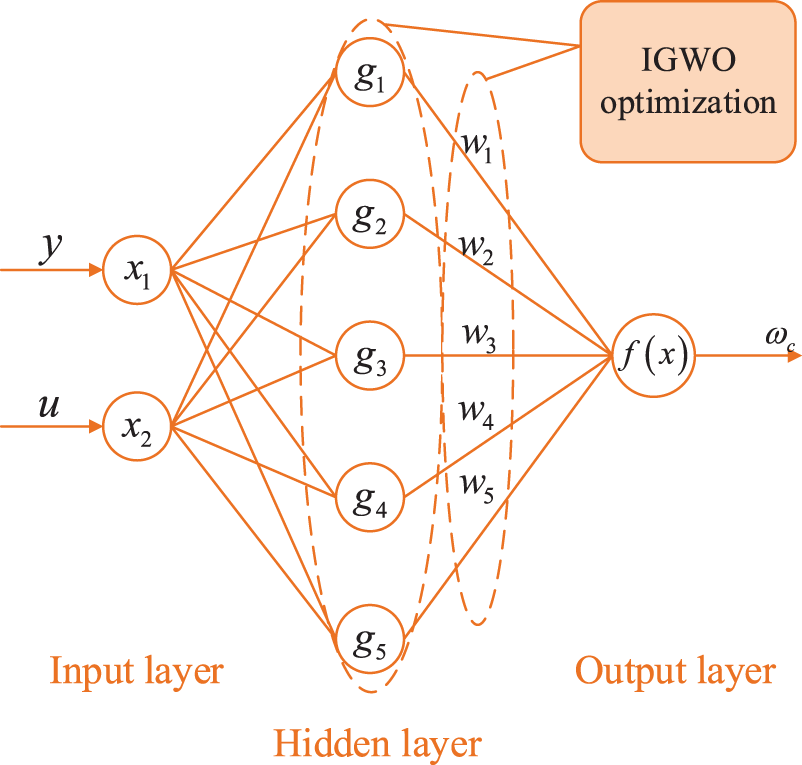
Figure 12: RBF neural network structure diagram
As shown in Fig. 12, the input to the RBF neural network is:
where
The neural network implicit layer output is:
where
Optimize the center vector and width vector in Eq. (44), this paper adds the improved Cubic chaotic mapping function to realize the initialization of the position distribution of wolves based on the traditional gray wolf algorithm to make its distribution more random, and the mapping function is shown in Eq. (45):
where the initial value of
The RBF neural network output layer input is:
where
The output of the RBF neural network results in:
where
where
The performance index function of the neural network in this article is:
where
where
The following outlines the implementation steps of the IGWO-RBF neural network model:
Step 1, initialize each parameter of the RBF neural network and the improved gray wolf algorithm.
Step 2, adopt the position update formula of the improved gray wolf algorithm to update the current position of the gray wolf, and use it as the center and width vectors of the RBF neural network to train the network.
Step 3, calculates the adaptation value of the gray wolf, determining whether it is less than the average value, and optimally determining the optimal update position.
Step 4, determine whether the number of iterations is reached or a set accuracy value is reached, if so, output a set of theoretically optimal parameters, if not, repeat from Step 2.
Step 5, assigns the optimal parameters to the RBF neural network, and the RBF neural network outputs the controller bandwidth at the current moment, which is substituted into ILADRC to obtain the output y.
Step 6, the error calculation is performed based on the output, if it does not meet the requirements then the weights are adjusted and updated, repeating from Step 2.
To verify the superiority of the IGWO-RBF algorithm proposed in this paper in the ILADRC control strategy, the second-order system in Eq. (51) is used as an example for simulation verification:
Simulation condition: the input signal is a step signal, the initial value is taken as 1, and it steps to 2 at 3 s, then a perturbation signal is added at 6 s, and the simulation results are shown in Fig. 13. From the figure, at 3 s, the IGWO-RBF-ILADRC control strategy reaches the steady state value earlier than the RBF-ILADRC control strategy, and at 6 s, with the addition of the perturbation, the output signal also has some fluctuations, but the fluctuation amplitude of the IGWO-RBF-ILADRC control strategy is low, and it can recover the steady state value quickly. Comprehensive analysis can prove that the IGWO-RBF-ILADRC control strategy proposed in this paper is superior to the traditional RBF-ILADRC control method and has stronger anti-interference ability.
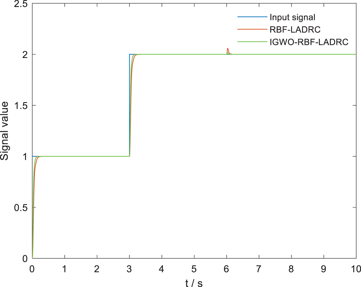
Figure 13: Comparison of the performance of the IGWO-RBF algorithm
To verify the feasibility and superiority of the control method proposed in this article, a simulation model of the VSG system based on ILADRC is constructed through the MATLAB/Simulink platform, and the parameters of the model are illustrated in Table 1.

4.1 Case 1: Simulation Analysis under Active Power Perturbation
Set the simulation conditions: the active power command changes from the original 20 to 10 kW at 0.5 s, and after 0.5 s, it returns to 20 kW at 1 s, and the simulation comparison and analysis are shown in Fig. 14.
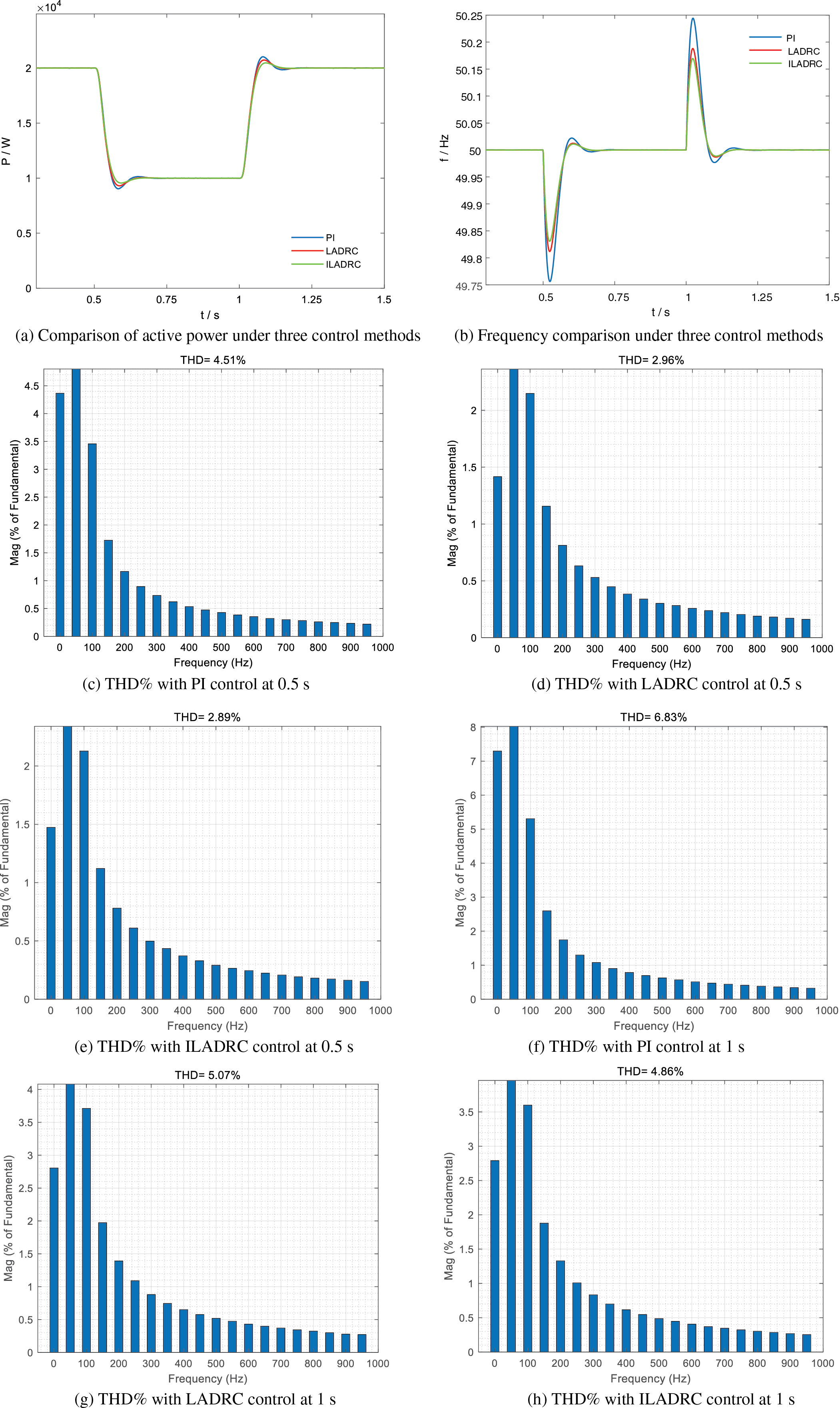
Figure 14: Active power disturbance analysis
In Fig. 14a, the active power changes are comparatively analyzed under the PI control strategy, LADRC control strategy, and ILADRC control strategy. It can be found by comparison that at 0.5 s, the power command decreases, and all three control strategies have a certain degree of overshooting fluctuation, in which the overshooting amount is 9.66% under PI control, 6.95% under LADRC control, and 4.44% under ILADRC control. The ILADRC control method proposed in this paper is found to have the lowest overshoot, and therefore, its anti-interference ability is also stronger. In terms of regulation time, the regulation time under PI control is 0.25 s, while the difference between the regulation time of LADRC control and ILADRC control is not much, both of them can reach the new steady state value in 0.2 s. The power command is restored to 20 kW at 1 s. At this time, the over-regulation under PI control is 5.12%, under LADRC control is 3.63%, and under ILADRC control is 2.33%. In comparison, it is found that the overshoot of the ILADRC control method proposed in the article is still the smallest, and it is also the strongest for the system’s anti-interference ability. In terms of regulation time, the regulation time of PI control is 0.24 s, and the difference between the LADRC control method and the ILADRC control method is not much, which is 0.2 s. In Fig. 14b, it is the comparison of the system frequency changes under the three control methods, and in terms of overshooting, the maximal overshooting amount of the PI control method is 0.48%, the LADRC control method is 0.36% and the ILADRC control method is 0.33%. In terms of regulation time, the regulation time of the PI control method is 0.25 s, and the regulation time of the LADRC control method and ILADRC control method is 0.2 s. Overall, the control method proposed in this text has certain advantages in terms of anti-interference ability and the ability to make the system restore stability quickly.
Fig. 14c–h displays the harmonic distortion rates of the system’s grid-connected current at 0.5 and 1 s for the PI, LADRC, and ILADRC control methods. At 0.5 s, the THD% for the PI control method is 4.51%, for the LADRC method is 2.96%, and for the ILADRC method is 2.89%. The ILADRC method reduces THD% by 1.62% compared to the PI method and by 0.07% compared to the LADRC method. At 1 s, the PI method has a THD% of 6.83%, the LADRC method 5.07%, and the ILADRC method 4.86%. The ILADRC method reduces THD% by 1.97% compared to the PI method and by 0.21% compared to the LADRC method. This analysis shows that the proposed control method enhances the power quality of the grid-connected system compared to traditional methods.
4.2 Case 2: Simulation Analysis under Grid Frequency Disturbances
Set the simulation conditions: the power grid frequency drops from the original 50 to 49.8 Hz at 0.5 s. After 0.5 s, it returns to 50 Hz at 1 s. The simulation comparison analysis is shown in Fig. 15.
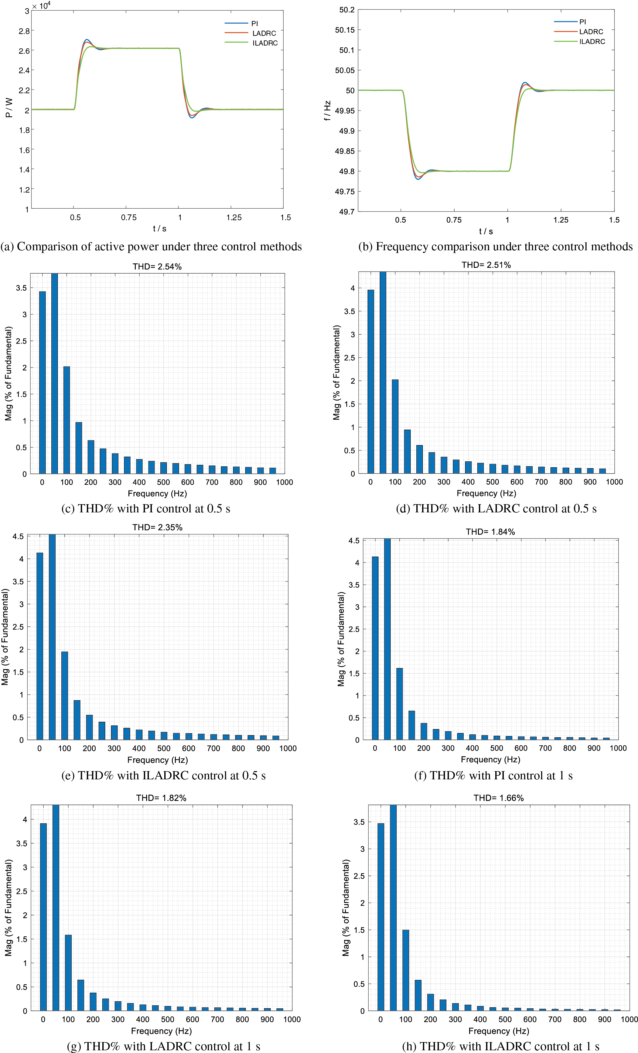
Figure 15: Grid frequency disturbance analysis
In Fig. 15a, the changes in active power under the PI control strategy, LADRC control strategy, and ILADRC control strategy are comparatively analyzed. Through comparison, it can be found that the decrease in grid frequency leads to an increase in system active power. During the change process, all three control strategies have certain fluctuations. Among them, the maximum overshoot under PI control is 4.25%, the maximum overshoot under LADRC control is 3%, and the maximum overshoot under ILADRC control is 0.91%. It is possible to see that the overshoot of the PI control method is the largest, while the overshoot of the control method proposed in this article is small, almost zero. From the perspective of adjustment time, the adjustment time under PI control is 0.2 s, while the adjustment time under LADRC control and ILADRC control is not much different, and the new steady-state value can be reached after 0.15 s. We should find that the overshoot of the ILADRC control method proposed in this text is still the smallest, and the anti-interference ability of the system is also the strongest. In Fig. 15b, the changes in system frequency under the three control strategies are compared. Regardless of the overshoot or the adjustment time, at the beginning and end of the system frequency decrease, the strategy proposed in this article can Quickly reach a new stable state and has strong anti-interference ability.
Fig. 15c–h shows the harmonic distortion rates of the grid-connected current at 0.5 and 1 s for the PI, LADRC, and ILADRC control methods. At 0.5 s, the THD% is 2.54% for PI control, 2.51% for LADRC control, and 2.35% for ILADRC control. The ILADRC method reduces THD% by 0.19% compared to the PI control and by 0.16% compared to the LADRC control. At 1 s, the THD% is 1.84% for PI control, 1.82% for LADRC control, and 1.66% for ILADRC control. The ILADRC method lowers THD% by 0.18% compared to the PI control and by 0.16% compared to the LADRC control. This analysis indicates that the proposed ILADRC method achieves the lowest harmonic distortion rate, enhancing the power quality of the grid-connected system, especially when grid frequency decreases.
In the article, the traditional PI control in VSG is improved, and LADRC is used to replace the PI control part in the voltage outer loop because of its strong anti-interference ability and fast dynamic response. Aiming at the problem of weak error tracking ability of traditional LADRC, it is improved by utilizing the deviation principle to obtain the ILADRC strategy used in this paper. Through the theoretical proof and the establishment of the corresponding simulation model, the following conclusions can be obtained: firstly, the ILADRC-based VSG grid-connected control method proposed in the article is proved to have strong tracking ability for system disturbances or external disturbances through theoretical analysis; secondly, for the problem of difficult to determine the bandwidth of the controller of the core parameters of the ILADRC, the IGWO-RBF proposed in this paper can be optimized through online tuning and optimized through the IGWO-RBF proposed in article. The neural network should be optimized online, which reduces the difficulty of parameter determination greatly; finally, from the beginning of the perturbation to reach the new steady state, the time used is shorter, and system overshoot is smaller, which affects system stability, so that the power quality of distributed power grid-connected power quality has been improved, and the system’s anti-interference ability has been improved. However, there are still some limitations in this paper, the method proposed in this paper is only simulated and verified in a single VSG, and not verified in a dual or multi-computer side-by-side VSG model, and the unfinished work will be taken as the content of further research in the later stage.
Acknowledgement: Sincere thanks to the editorial staff of Energy Engineering Journal and the expert teachers who reviewed this paper, due to your valuable comments, this paper can be sublimated again, thank you for your guidance.
Funding Statement: This research was supported by the Lanzhou Jiaotong University-Southwest Jiaotong University Joint Innovation Fund (LH2024027).
Author Contributions: The authors confirm contribution to the paper as follows: study conception and design: Xin Mao, Hongsheng Su; data collection: Jingxiu Li; analysis and interpretation of results: Xin Mao, Hongsheng Su, Jingxiu Li; draft manuscript preparation: Xin Mao. All authors reviewed the results and approved the final version of the manuscript.
Availability of Data and Materials: All data generated or analyzed during this study are included in this published article.
Ethics Approval: Not applicable.
Conflicts of Interest: The authors declare that they have no conflicts of interest to report regarding the present study.
References
1. W. J. Sang, W. Y. Guo, S. T. Dai, C. Y. Tian, S. H. Yu and Y. P. Teng, “Virtual synchronous generator, a comprehensive overview,” Energies, vol. 15, no. 17, Aug. 2022, Art. no. 6148. doi: 10.3390/en15176148. [Google Scholar] [CrossRef]
2. M. Abuagreb, M. F. Allehyani, and B. K. Johnson, “Overview of virtual synchronous generators: Existing projects, challenges, and future trends,” Electronics, vol. 11, no. 18, Sep. 2022, Art. no. 2843. doi: 10.3390/electronics11182843. [Google Scholar] [CrossRef]
3. Y. X. Chen, Y. P. Wang, and Q. Wang, “Parametric adaptive inverter VSG control strategy with transient damping characteristics,” IEICE Electron. Express, vol. 21, no. 5, Jan. 2024, Art. no. 20230558. doi: 10.1587/elex.21.20230558. [Google Scholar] [CrossRef]
4. W. L. Yang, C. M. Tu, F. Xiao, and Q. Guo, “Transient stability enhancement method of VSG with frequency stability improvement,” (in ChineseProc. CSEE, Jan. 2024. doi: 10.13334/j.0258-8013.pcsee.232145. [Google Scholar] [CrossRef]
5. M. D. Wang, A. D. Yang, and H. J. Li, “Research on inertia lifting of new power system based on VSG double sagging optimization control,” in 2nd Int. Conf. Smart Energy Energy Internet Things, Guilin, China, Jun. 16–18, 2023. [Google Scholar]
6. M. W. Ren, T. Li, K. Shi, P. F. Xu, and Y. X. Sun, “Coordinated control strategy of virtual synchronous generator based on adaptive moment of inertia and virtual impedance,” IEEE J. Emerg. Sel. Top. Circuits Syst., vol. 11, no. 1, pp. 99–110, Mar. 2021. doi: 10.1109/JETCAS.2021.3051320. [Google Scholar] [CrossRef]
7. Z. T. Ling, Y. T. Liu, Z. P. Wang, and J. Yin, “Adaptive inertia and damping of grid-connected inverter with improved VSG control,” IET Power Electron., vol. 16, no. 16, pp. 2769–2781, Oct. 2023. doi: 10.1049/pel2.12600. [Google Scholar] [CrossRef]
8. F. J. Yao, J. B. Zhao, X. J. Li, L. Mao, and K. Q. Qu, “RBF neural network based virtual synchronous generator control with improved frequency stability,” IEEE Trans. Ind. Inform., vol. 17, no. 6, pp. 4014–4024, Jun. 2021. doi: 10.1109/TII.2020.3011810. [Google Scholar] [CrossRef]
9. X. H. Yang, H. Li, W. Jia, Z. X. Liu, Y. Pan and F. W. Qian, “Adaptive virtual synchronous generator based on model predictive control with improved frequency stability,” Energies, vol. 15, Nov. 2021, Art. no. 8385. doi: 10.3390/en15228385. [Google Scholar] [CrossRef]
10. Z. Gao, “Scaling and bandwidth-parameterization based controller tuning,” in Proc. 2003 Am. Control Conf., Denver, CO, USA, Jun. 4–6, 2003. [Google Scholar]
11. Z. J. Liu, F. N. Li, P. Yang, X. Lin, and G. Z. Zhang, “Frequency modulation control of grid-forming converter based on LADRC-MI,” Energies, vol. 17, no. 13, Jul. 2024, Art. no. 3282. doi: 10.3390/en17133282. [Google Scholar] [CrossRef]
12. Y. Y. Zhang, J. Z. Zhu, X. Y. Dong, P. C. Zhao, P. Ge and X. L. Zhang, “A control strategy for smooth power tracking of a grid-connected virtual synchronous generator based on linear active disturbance rejection control,” Energies, vol. 12, no. 15, Aug. 2019, Art. no. 3024. doi: 10.3390/en12153024. [Google Scholar] [CrossRef]
13. S. Li, Y. L. Li, X. L. Chen, W. T. Jiang, X. K. Li and T. Li, “Control strategies of grid-connection and operation based on active disturbance rejection control for virtual synchronous generator,” Int. J. Electr. Power Energy Syst., vol. 123, Jun. 2020. Art. no. 106144. doi: 10.1016/j.ijepes.2020.106144. [Google Scholar] [CrossRef]
14. J. C. Lin, S. Q. Liu, and G. Wang, “Harmonic suppression of active disturbance rejection control for virtual synchronous generators,” Int. J. Circuit Theory Appl, vol. 52, no. 1, pp. 1–20, Mar. 2024. doi: 10.1002/cta.3753. [Google Scholar] [CrossRef]
15. C. Lyu, S. He, W. Q. Wang, W. Chen, L. Q. Kong and X. Q. Wang, “Control strategy of virtual synchronous generator grid-connected inverter based on linear active disturbance rejection and repetitive control,” (in ChineseSci. Technol. Eng., vol. 21, no. 36, pp. 15460–15468, Aug. 2021. [Google Scholar]
16. W. T. Liu, T. Zhao, Z. W. Wu, and H. Wei, “Linear active disturbance rejection control for hysteresis compensation based on backpropagation neural networks adaptive control,” Trans. Inst. Meas. Contr., vol. 43, no. 4, pp. 915–924, Feb. 2021. doi: 10.1177/0142331220934948. [Google Scholar] [CrossRef]
17. Z. Qiao et al., “Simulation of a quadrotor under linear active disturbance rejection,” Appl. Sci., vol. 12, no. 23, Dec. 2022, Art. no. 12455. doi: 10.3390/app122312455. [Google Scholar] [CrossRef]
18. D. S. Sun and Y. J. Zhang, “Improvement and observation ac-curacy analysis of linear extended state observer,” (in ChineseJ. Nat. Univ. Def., vol. 39, no. 6, pp. 111–117, Dec. 2017. doi: 10.11887/j.cn.201706017. [Google Scholar] [CrossRef]
19. W. J. Ma, Y. P. Guan, and B. Zhang, “Active disturbance rejection control-based control strategy for virtual synchronous generators,” (in ChineseIEEE Trans. Energy Convers., vol. 35, no. 4, pp. 1747–1761, Dec. 2020. doi: 10.1109/TEC.2020.2991737. [Google Scholar] [CrossRef]
20. J. S. Dai and J. Lyu, “Design of double closed-loop pi regulator for gird-connected inverter in wind power system,” (in ChineseElectrotechnics Electr., no. 9, pp. 5–9, Sep. 2011. [Google Scholar]
21. Q. Liang, C. B. Wang, J. W. Pan, Y. H. Wei, and Y. Wang, “Parameter identification of b0 and parameter tuning law in linear active disturbance rejection control,” (in ChineseControl Decis., vol. 30, no. 9, pp. 1691–1695, Sep. 2015. doi: 10.13195/j.kzyjc.2014.0943. [Google Scholar] [CrossRef]
Cite This Article
 Copyright © 2024 The Author(s). Published by Tech Science Press.
This work is licensed under a Creative Commons Attribution 4.0 International License , which permits unrestricted use, distribution, and reproduction in any medium, provided the original work is properly cited.


 Submit a Paper
 Propose a Special lssue
 View Full Text
 Download PDF
 Downloads
 Citation Tools