 Open Access
ARTICLE
The Hydraulic Fracturing Optimization for Stacked Tight Gas Reservoirs Using Multilayers and Multiwells Fracturing Strategies
1 School of Petroleum Engineering, China University of Petroleum (East China), Qingdao, 266580, China
2 State Key Laboratory of Deep Oil and Gas, China University of Petroleum (East China), Qingdao, 266580, China
3 Research Institute of Petroleum Engineering Technology Sinopec Northwest Oilfield Company, Urumqi, 830011, China
4 Reservoir Engineering Unit, Yuanwang Jingsheng Technology (Beijing) Co., Ltd., Beijing, 100083, China
* Corresponding Author: Xian Shi. Email:
(This article belongs to the Special Issue: Integrated Geology-Engineering Simulation and Optimizationfor Unconventional Oil and Gas Reservoirs)
Energy Engineering 2024, 121(12), 3667-3688. https://doi.org/10.32604/ee.2024.056266
Received 18 July 2024; Accepted 29 September 2024; Issue published 22 November 2024
Abstract
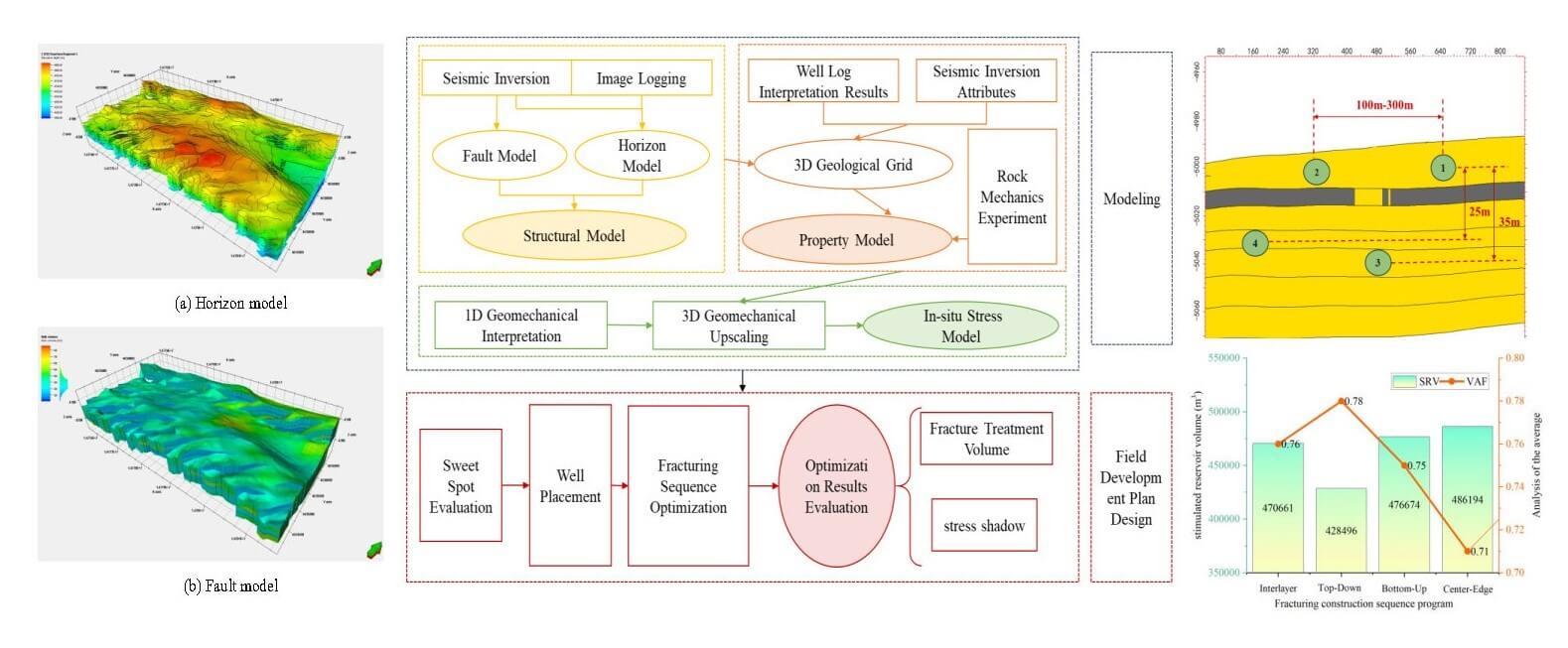
Based on a geology-engineering sweet spot evaluation, the high-quality reservoir zones and horizontal well landing points were determined. Subsequently, fracture propagation and production were simulated with a multilayer fracturing scenario. The optimal hydraulic fracturing strategy for the multilayer fracturing network was determined by introducing a vertical asymmetry factor. This strategy aimed to minimize stress shadowing effects in the vertical direction while maximizing the stimulated reservoir volume (SRV). The study found that the small vertical layer spacing of high-quality reservoirs and the presence of stress-masking layers (with a stress difference of approximately 3~8 MPa) indicate that interlayer stress interference from multilayers and multiwells fracturing between neighboring developed formations could affect the longitudinal propagation of the reservoirs. In addition, this study investigated well spacing optimization by comparing uniformly spaced wells (100–300 m) with asymmetric spaced wells (200 m upper layer, 250 m lower layer). Numerical results indicated that asymmetric spaced well placement yielded the largest stimulated reservoir volume (SRV) of 73,082 m3, representing a 65.42% increase compared to 100 m spaced wells. Furthermore, four different hydraulic fracturing sequences (interlayer, up-down, down-up, and center-edge) were compared for multilayer and multiwell networks. The center-edge sequence exhibited the lowest vertical asymmetry factor (0.71) and the least stress shadowing effects compared to the other sequences (0.78 for interlayer, 0.75 for up-down, and 0.76 for down-up). This sequence also achieved the largest SRV (486,194 m3), representing an 11.87% increase compared to the down-up sequence. Therefore, the center-edge fracturing sequence is recommended for multilayer development in this block. These results offer valuable insights for optimizing well placement and fracturing sequence design in multilayer well networks, ultimately advancing the development of multilayer fracturing technology in the region.Graphic Abstract
Keywords
Tight gas reservoirs are widely distributed, and hydraulic fracturing is commonly used to stimulate them. To optimize drilling cost and recovery rate, it is crucial to access adjacent productive zones from a single well pad, especially in thick tight reservoirs with multilayers. However, in such formations, efficiently utilizing each layer poses a significant challenge, particularly in minimizing well interference during production. Due to the strong heterogeneity of tight gas reservoirs, where each layer is thin but numerous, designing hydraulic fracturing for thick stacked formations remains challenging in the oil and gas community [1–3]. The multilayer and multiwell network development strategy is a key technical approach for stacked reservoir development. Its advantage lies in enabling overall utilization of the oil and gas field through a network of multilayer wells, rather than relying on single-well production, leading to higher development efficiency and long-term production enhancement [4,5]. Unlike traditional stimulation methods for single layers, hydraulic fracturing in multilayer and multiwell scenarios must consider well interference in vertical and lateral directions.
The multilayers and multiwells network development mode is mainly used for unconventional reservoirs such as shale gas reservoirs in North America, such as Haynesville, Bakken, Bossier, and other shale blocks, where the development mode of “tight-spaced wells” and “multiple wells network” has been commonly adopted [6,7]. However, the application of multilayers and multiwells networks is still new in China, only the Fuling shale gas field, Changning-Weyuan, and other shale gas reservoirs are mainly used but the production rate is not absolutely ideal [8]. Multilayers and multiwells fracturing generally emphasize the development and the overall utilization of oil and gas fields as a compete for reservoir pay zone, so it involves the spatial layout of vertical and horizontal well spacing, otherwise, there may be problems such as inter-well pressure interference and inter-well interference, resulting strong frac hits problems in the production process. Therefore, the research on multilayers well networks has received extensive attention from more and more scholars in recent years [9,10]. Alimahomed et al. carried out a study of the deployment mode of the stereoscopic well network for the Midland block by using logging data and numerical simulation methods and obtained a model of the stereoscopic well network through production simulation [11]. Alimahomed et al. used logging data and numerical simulation methods to study the pattern of well placement in the Midland block and obtained the optimal multilayers well network scheme through production simulation [12]. Meanwhile, taking the Delaware basin as an example, they focused on the effects of vertical stress shadowing effects and fracturing sequence on the production rate, and the results showed that the production rate of the wells with interlayer vertical interference was reduced by 50% during the production process. The results show that the production rate of wells with interlayer vertical interference decreases by 50% during production and the production rate increases by 7% when working from the bottom to the top. Liu et al. simulated five fracturing modes, including single well fracturing, jump fracturing, two horizontal wells simultaneous fracturing, zipper fracturing, and improved zipper fracturing, and the results proved that the fracturing mode and sequence affect the fracturing effect, and the induced stress can be utilized by adjusting the process [13]. Thompson et al. once proposed the “Tank” conceptual development for the Midland basin, which aims to realize the efficient development of a high-density well network and to control the reservoir stress barrier by adjusting the fracturing sequence to prevent the occurrence of stress shadowing effects and interlayer compression in the small spacing between wells [14], and the scheme can be used for the development of a high-density well network and can be used in the development of a high-density well network. be used for high-density well network development to minimize well interference while optimizing production enhancement, production, and operational efficiencies. Wang et al. designed different well placement models such as homogeneous well network and multilayer well network, and the study showed that the multilayer well network reduces the intensity of inter-well interference between planar wells while improving the overall degree of reserve utilization, providing adjustment space for the reduction of well spacing [15], and at the same time quantifying the degree of inter-well stress shadowing effects to reasonably adjust the spacing between wells. The multilayer and multiwells network can improve the overall utilization of reserves while reducing the intensity of interference between planar wells, which provides space for adjustment of well spacing. Li et al. designed a geo-engineering integrated sweet spot evaluation model of a multilayers and multiwells network for dense sandstone reservoirs and formed key development technologies such as deployment of a multilayer development well network with close-spaced wells, interference control, fracturing optimization, and multivariate synergy [16]. The application results showed that the reserve utilization rate of the small-well spacing development mode was greatly improved, and the recovery rate was significantly increased. As shown in Table 1, research on three-dimensional development has primarily focused on shale formations. There is a significant gap in research concerning the application of development in tight clastic reservoirs. This presents a crucial area for future investigation. Furthermore, North American multilayers and multiwells network development emphasize vertical “full-wave” efficient transformation technology, but the precision of seam height propagation is limited [17,18]. Conversely, domestic reservoir thickness is generally thin, necessitating detailed reservoir characterization and sweet spot evaluation to ensure fracture propagation within the production layer and optimal multi-layer stimulation. The key to optimizing well placement in multilayers and multiwells networks remains the integration of sweet spot evaluation and multilayer stress shadowing effects analysis. This combined approach allows for effective coverage of the development system. Moreover, optimizing the fracturing sequence mitigates interlayer and inter-well stress shadowing effects, maximizing the stimulated reservoir volume and ultimately enhancing reserve utilization [19,20]. Current research highlights limitations in maximizing the effectiveness of multilayers and multiwells network development in tight clastic reservoirs, including a limited understanding of optimal well placement and spacing strategies for thin, layered reservoirs.

This study employs an integrated geological engineering model to optimize fracturing sequences for the tight gas reservoir using multilayers well placement in the Junggar Basin. A dual sweet spot evaluation model, incorporating both geological and engineering parameters, was employed to optimize well placement. Fracture propagation was simulated numerically to develop an optimal fracturing scheme. The resulting plan aims to maximize stimulated reservoir volume (SRV) while minimizing stress shadowing effects between layers, establishing an effective fracturing strategy for reservoir stimulation. These findings provide valuable insights for optimizing multilayers fracturing design in the region.
2.1 Fracturing Stimulation Design for Multilayers and Multiwells Network Development
High-resolution integrated geo-engineering modeling can be used for the pinpoint design of multilayer fracturing development strategies in tight reservoirs. Well placement plays a critical role in the multilayer fracturing treatment and a good understanding of reservoir properties and geomechanical characteristics is necessary. The establishment of geo-engineering model typically involves characterizing reservoir and mechanical properties based on in-situ stress the combination of tectonic setting, seismic attributes, and well-log information. Moreover, the utilization of dual-sweet spot modeling is also necessary to guide a landing point selection and horizontal wells trajectory design, thus resulting larger fracture contact area. A hierarchical multi-layer modeling approach, integrating tectonic, attribute, natural fracture, and in-situ stress models, is employed to characterize reservoir properties with high resolution. This approach leverages multi-source data, including seismic and well logs. The tectonic model, comprising structural and fault models, is calibrated using seismic data, guide well logs, and horizontal well logs. The attribute model incorporates parameters indicative of reservoir quality, such as lithology, brittleness, and hydrocarbon saturation. Natural fractures are modeled and analyzed using pre-stack seismic data, image logs, and well logs. An in-situ stress model, informed by rock mechanical properties (e.g., Young’s modulus, Poisson’s ratio), guides the design of hydraulic fracture propagation simulations and dual-sweet spot identification. In-situ stress simulation is conducted using a geomechanical model, calibrated through an iterative process involving an optimized particle swarm algorithm, culminating in a multilayer finite element in-situ stress model.
Given the significant longitudinal extent of the reservoir, limited thickness of high-quality pay zones, and potential for interlayer stress shadowing effects during fracturing, this study prioritizes optimizing fracture height growth and fracturing sequence. This optimization aims to stagger the placement of “star” and “W-shaped” wells, maximizing stimulated reservoir volume (SRV). Fig. 1 outlines the technical roadmap for designing the multilayer and multiwells network development strategy.
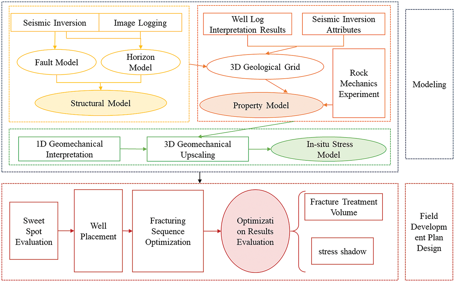
Figure 1: A workflow for designing multilayers and multiwells network development program
The Junggar Basin is selected as the study area and the target in this basin can be characterized by tight clastic gas reservoirs with substantial cumulative thickness, thin individual layers, wide vertical distribution, and strong heterogeneity, which poses significant challenges to traditional layered fracturing development and results in low economic benefits. The study block is located in the eastern part of the Yakla Fault of the Shaya Uplift in the Junggar Basin, which is characterized by the development of faults, natural cracks, and significant present-day stress anisotropy, making the overall development difficult. The proven gas-bearing area of this block is 4.32 km2, the geological reserves of natural gas are 22.08 × 10⁸ m3, and the buried depth of the research reservoir is about 5000 m. The lithology of the target reservoir is mainly feldspathic clastic sandstone, in which the quartz content is 65%, feldspar content is 21%, and the clastic content is 13%, see the microscopic observation in Fig. 2a. The average permeability is about 1–100 mD, and thus hydraulic fracturing is the critical method for commercial reservoir production. The interpretation of the basic properties of the reservoir is realized through the integration of well log data, and the results show that the 5025–5050 m layer system has low water saturation and can be regarded as the primary gas-bearing zone, as shown Fig. 2b.
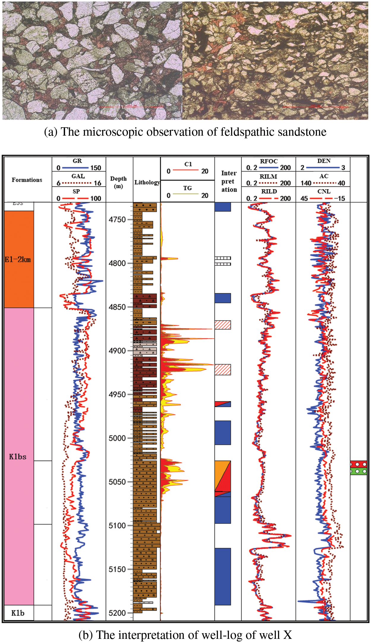
Figure 2: The microscopic observation and well-log of a typical well X
3 Geological-Engineering Integrated Modeling
A high-resolution structural model was constructed by integrating well-log and 3D seismic data using a detailed tectonic modeling technique. This model comprises both horizon and fault models, calibrated and refined using well-log interpretation and seismic attributes. The fault model was constructed by analyzing interpreted fault data extracted from the 3D seismic volume. Fault interactions were evaluated, and a comprehensive fault model was generated through a geologically constrained interpretation process. Utilizing this fault model as a framework, a horizon model was generated, guided by interpreted seismic horizons. Well-log data were then incorporated to refine the horizon model for each layer, resulting in a detailed 3D geological model of the study area. The finalized geological model consists of a 601 × 301 × 28 grid system (Fig. 3), with a horizontal resolution of 10 m × 10 m, totaling approximately 5.03 million grid cells. This resolution is able to satisfy the computational requirements for accurate fracture propagation and production simulation.
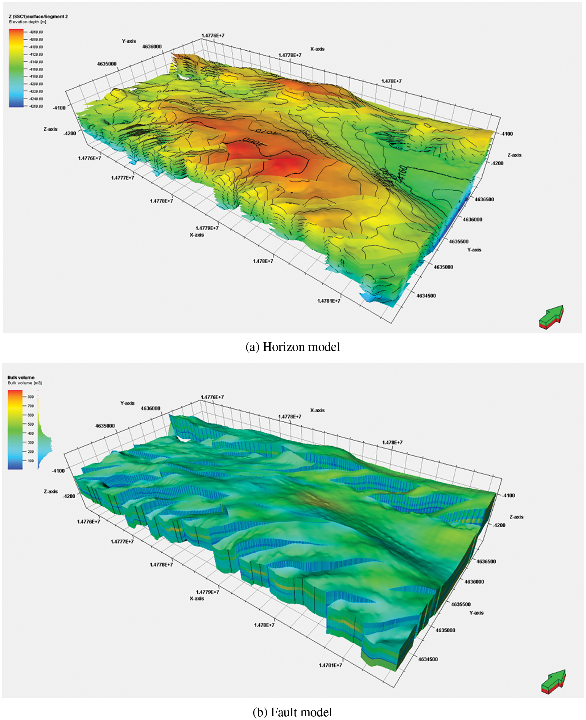
Figure 3: The sructural model of the study block
3.2 Reservoir Property and Geomechanical Modeling
Reservoir attribute modeling characterizes the spatial distribution of reservoir properties, providing a quantitative basis for reservoir simulation. This study employs a multi-faceted approach, integrating core analysis data, well-log interpretations, and seismic attributes (including inverted properties) within a geostatistical framework. This approach ensures a robust and reliable reservoir property model, essential for subsequent numerical simulation. Various attribute modeling techniques were considered, including deterministic methods (e.g., kriging), geostatistical methods, and stochastic simulations (e.g., sequential Gaussian simulation). Based on an evaluation of data availability and reservoir heterogeneity, classical kriging was selected for this study. This method utilizes well-based core analysis and log interpretation results, along with seismically-derived reservoir property estimates, to generate high-resolution 3D property models (Fig. 4). The resulting models indicate that porosity ranges predominantly from 12% to 18%, permeability varies between 1 and 100 mD, and gas saturation falls between 40% and 100%. In addition to these properties, a comprehensive suite of geomechanical properties, including Young’s modulus, Poisson’s ratio, brittleness index, uniaxial compressive strength, uniaxial tensile strength, cohesion, and angle of internal friction, was also modeled. These models are essential for identifying geomechanical sweet spots and optimizing well placement.
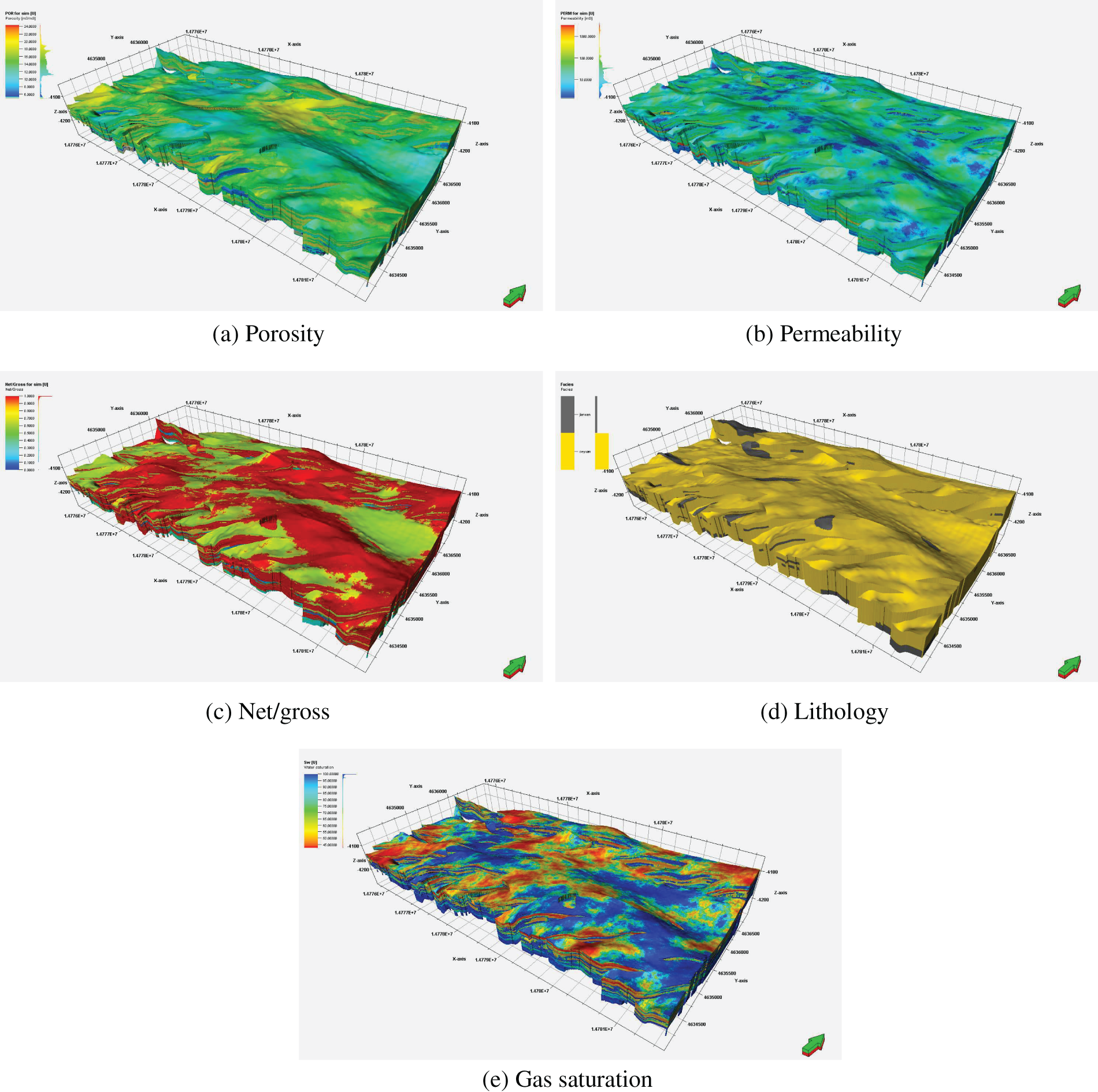
Figure 4: Reservoir properties model of study block
Accurate characterization of in-situ stress magnitude and direction is crucial for optimizing well placement and hydraulic fracturing design. In this study, a comprehensive approach was employed to estimate the in-situ stress profile with finite element modeling and core experiments. The single well in-situ stress approach needs to integrate well-log data, laboratory measurements, and acoustic emission (AE) analysis. Vertical stresses were determined by integrating density logs, while pore pressure was estimated using Eaton’s method. Laboratory AE tests were conducted on core samples to determine the magnitude of the minimum and maximum horizontal stresses. The Kaiser effect, based on the observation that rock samples emit acoustic signals when subjected to stresses exceeding their previous maximum stress, provides a reliable method for stress estimation [21]. Three core samples, oriented at 45° increments in the horizontal plane perpendicular to the wellbore axis, were extracted from the target formation for AE testing. By measuring the acoustic emissions during controlled loading, the magnitudes of the maximum and minimum horizontal stresses were determined. The AE-derived in-situ stress was calculated using the following equation:
where: σv is the overburden stress, MPa; σH and σh are the maximum and minimum horizontal stress, MPa;
Core samples of tight clastic rocks were acquired at depths of 5017.4 and 5020.6 m. Acoustic emission measurements were performed on the cores, and the processed data are presented in Fig. 5 and Table 2. Previous results indicate that differential horizontal stress exceeding 5 MPa creates a stress barrier that inhibits fracture propagation in the vertical direction. Experimental In-situ stress evaluation in two key layers reveals an average stress difference of 5–9 MPa within the developed layer system, suggesting a notable interlayer fracture containment g effect. A total of six sub-layers are composed of the target formation. By integrating in-situ stress evaluation curves, reservoir properties analysis, and gas reservoir evaluation, it is determined that optimal drilling rates in high-quality reservoirs are achieved when fabric wells for multilayers development are strategically positioned within sub-layers ④, ⑤, and ⑥ (Fig. 6).
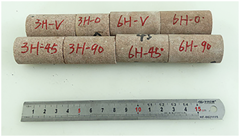
Figure 5: Test samples of acoustic emission measurements

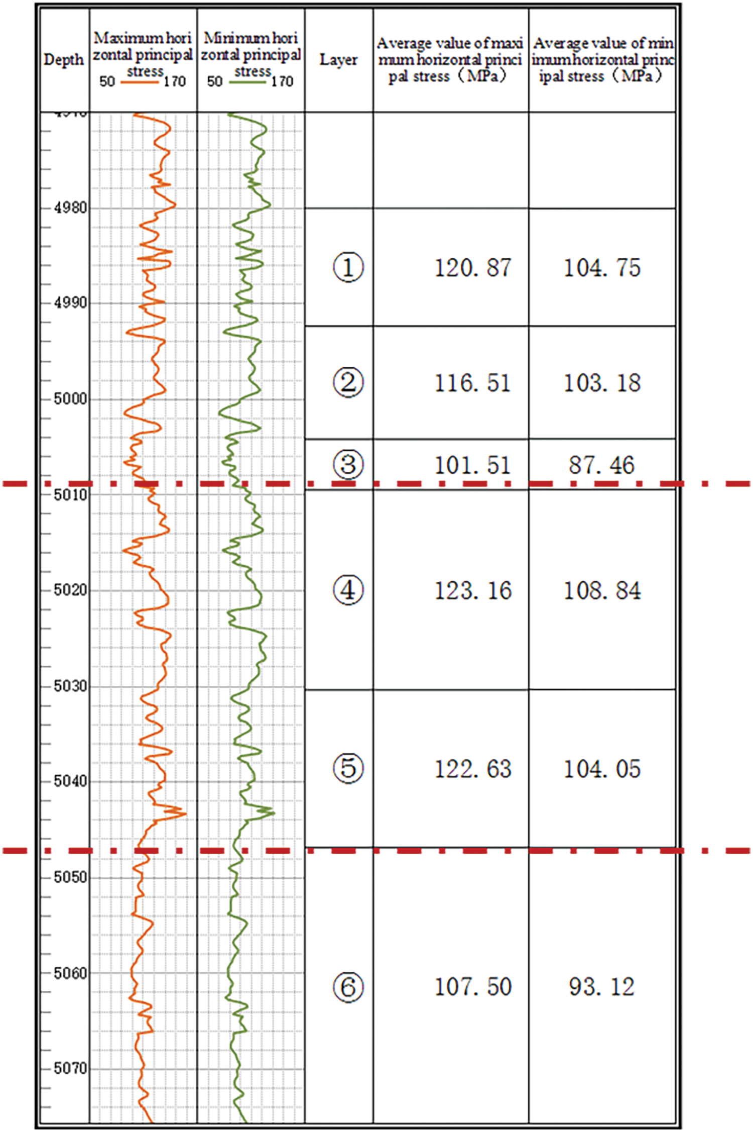
Figure 6: Stress in different layers
The Junggar Basin presents significant challenges for hydraulic fracturing design due to its complex in-situ stress in situ stress regime. The basin’s intricate tectonic history and heterogeneous rock properties result in a complex stress field, which is further complicated by the influence of surface topography, faults, and natural fractures. Traditional geomechanical modeling approaches often are unable to accurately in-situ stress characterization. To address this problem, an in-situ stress fault-constrained geomechanical model was employed, utilizing spatial inversion of the constructed in-situ stress field and iterative trial calculations to determine the three-dimensional in-situ stress distribution. This model’s accuracy was also validated by comparing the stress profile from a single well, demonstrating a satisfactory match. Numerical simulations conducted within the study area revealed a vertical stress (σv) range of 139–142 MPa, a maximum horizontal stress (σH) range of 116–119 MPa, and a minimum horizontal stress (σh) range of 101–104 MPa. The significant difference between σH and σh not only indicates a strike-slip faulting regime but also signifies the creation of complex fracture networks using conventional hydraulic fracturing techniques is difficult under current large horizontal stress differences.
4 Optimization of Hydraulic Fracturing Design and Sequence for Multilayers and Multiwells Network
4.1 Sweet Spot Identification and Well Placement
Identifying the reservoir sweet spot is crucial for optimizing well placement and hydraulic fracturing design in multilayers and multiwells network. This study employs a dual sweet spot evaluation method to identify optimal target zones. This approach considers both geological and engineering parameters to provide a comprehensive assessment of reservoir quality. Fracturing sweet spots typically encompass geological and engineering aspects. Geological sweet spots are regions rich in oil and gas resources with favorable reservoir properties, assessed based on physical properties and oil and gas saturation. Porosity and permeability primarily determine physical properties, providing a comprehensive understanding of reservoir quality. Oil and gas saturation indicates the distribution of hydrocarbons in the reservoir and plays a crucial role in fracturing outcomes. From an engineering perspective, under the same hydraulic fracturing process conditions, noticeable differences exist in fracture networks formed in reservoirs with varying geomechanical properties. Engineering fracability is primarily based on the brittleness index, which is a key indicator for selecting favorable reservoir intervals for hydraulic fracturing. However, such fracability evaluation methods may not fully and scientifically characterize the fracability of shale formations. Therefore, a comprehensive engineering evaluation of fracability is required to consider factors such as fracture toughness and stress heterogeneity coefficient. This study utilizes these parameters to identify a “dual sweet spot” within the study area, guiding the selection of optimal well placement layers. A hierarchical analysis, combined with an entropy weighting method, was employed to determine the relative importance of each parameter. hierarchical analysis effectively incorporates expert knowledge and judgment regarding parameter relationships, while the entropy weighting method objectively quantifies the information content of each parameter based on data variability. Subsequently, dimensionless geological and engineering sweet spot indices were calculated through index normalization, with higher values representing more favorable reservoir conditions. The calculation formula for the sweet spot index is as Eq. (5). Results are shown in Table 3.

where:
The weights obtained from the analysis are brought into Eq. (5) to obtain the sweet spot evaluation formula as follows:
where:
The target formation, located between 4900 and 5200 m depth, was evaluated for sweet spot potential. Using the sweet spot evaluation model developed in this study (Fig. 7), an average sweet spot profile was generated for each sub-layer within the target zone. Integrating these profiles with the vertical stress difference-based layering scheme, two sections: 5010–5030 m and 5045–5055 m, were identified as high-quality well placement zones exhibiting favorable geological and engineering characteristics. These zones were then further evaluated to determine optimal landing points for horizontal wells.
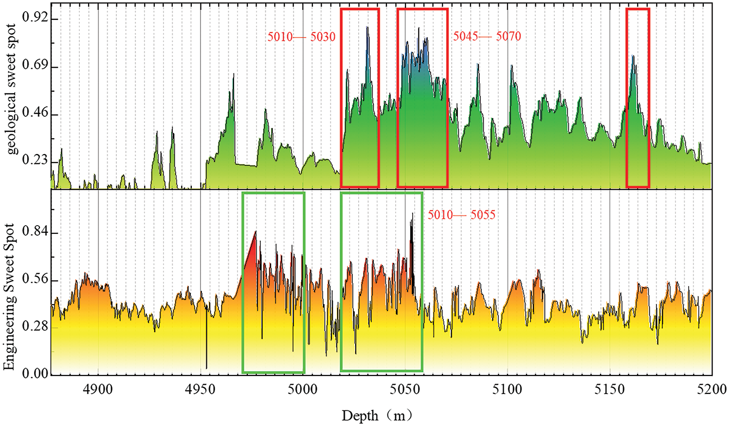
Figure 7: Results of geological-engineering dual sweet spot evaluation of clastic reservoirs in the study block
Optimizing well placement in a multilayer and multiwells network requires considering not only sweet spot distribution but also the potential for stress shadowing effects between wells. Hydraulic fracturing operations alter the in-situ stress field. Given the identified sweet spot distribution and a vertical layer spacing of 25–35 m, a parallel well placement strategy would likely result in significant stress shadowing effects, compromising fracturing effectiveness. This interference occurs because the high-pressure fluid injection during hydraulic fracturing creates a zone of increased stress around each well. When wells are placed too close together, these stress zones overlap, hindering fracture propagation and potentially leading to premature fracture termination. This ultimately reduces the effectiveness of the fracturing process and limits the stimulated reservoir volume (SRV). To mitigate this, a staggered well placement pattern is adopted (Fig. 8). This strategy, as illustrated with a three-well example, can effectively minimize stress shadowing effects between wells within the same layer and reduce interlayer interference compared to a parallel well placement. This multilayer staggered well placement approach maximizes reservoir contact while minimizing detrimental stress shadowing effects. A preliminary design utilizing four wells in a staggered placement was developed for the study area (Fig. 9). Wells 1 and 2 are placed within the first target zone, while Wells 3 and 4 are positioned in the second target zone, maintaining a vertical well spacing of 25–35 m. This placement minimizes interlayer stress shadowing effects, ensuring effective reservoir stimulation.
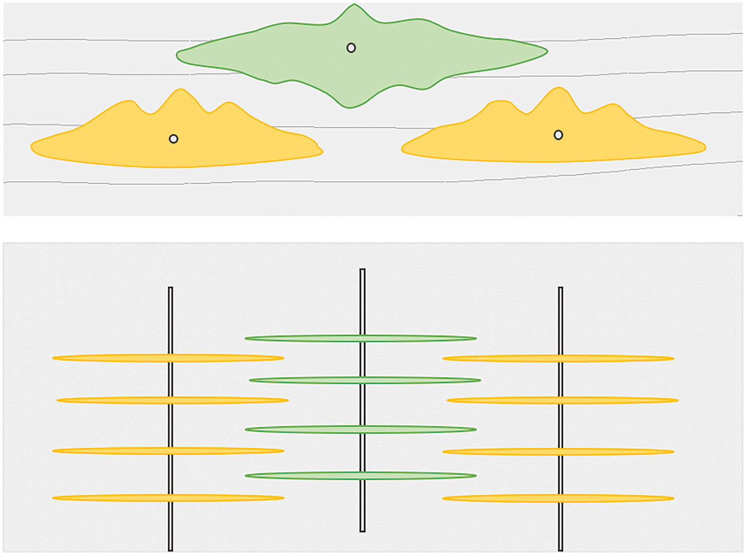
Figure 8: A staggered well placement pattern
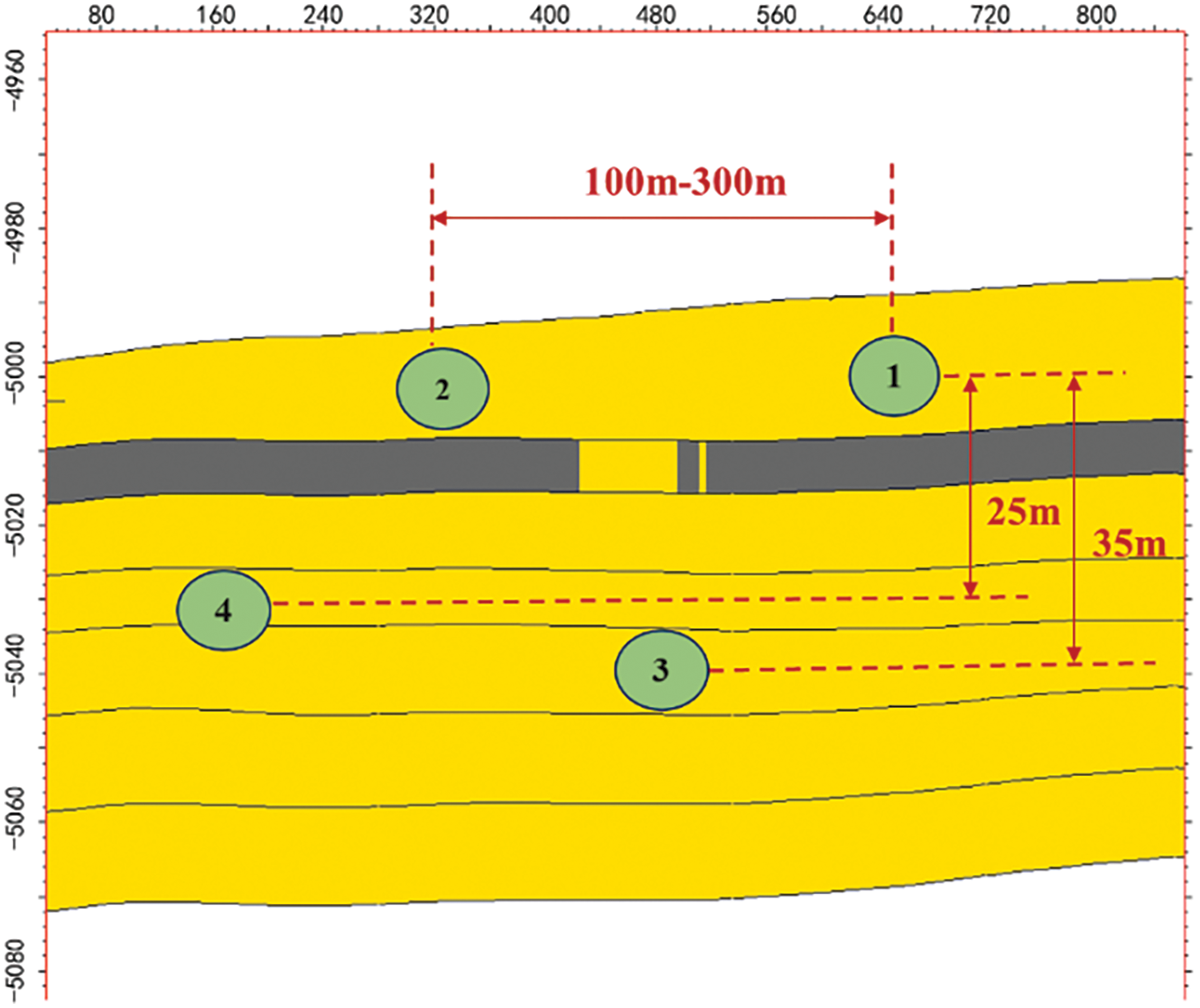
Figure 9: Multilayers and multiwells network in the studied reservoirs
Well spacing is a critical parameter in multilayer hydraulic fracturing design, significantly influencing stimulated reservoir volume (SRV), and well productivity. Excessively close well spacing can lead to strong fracture interference and frac hit during the production period. Conversely, the large well spacing increases drilling costs and may leave significant portions of the untapped reservoir, reducing the overall development efficiency of target formation. Four well spacing scenarios are considered during the hydraulic fracturing: 100, 200, 300 m, and an asymmetric spacing with 200 m between the upper wells and 250 m between the lower wells (Fig. 10).
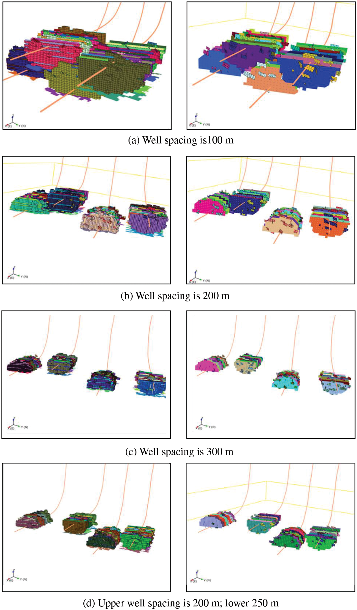
Figure 10: Stimulated reservoir volume for different well spacing
(1) When the well spacing is 100 m, significant fracture interference occurs, resulting in limited SRV growth due to the merging of hydraulic fractures.
(2) When the well spacing is 200 m, fracture interference is minimized, leading to a substantial increase in SRV and potentially maximizing well productivity.
(3) While fracture interference is negligible when well spacing is about 300 m, the wider spacing may leave portions of the reservoir unstimulated, potentially limiting overall recovery efficiency.
(4) When an asymmetric well spacing placement, with 200 m between the upper wells and 250 m between the lower wells, represents a staggered pattern that balances SRV growth with minimizing stress shadowing effects, potentially offering an optimal balance for this specific reservoir.
In conclusion, optimizing well spacing is crucial for maximizing the economic viability of shale gas development. The trade-offs between well spacing, drilling costs, and long-term productivity must be carefully considered. While asymmetric spacing appears promising based on our simulations, further research, including economic modeling and field trials, is necessary to determine the optimal well spacing strategy for specific reservoir conditions.
4.3 Hydraulic Fracturing Sequence Design for Multilayers and Multiwells Network
Building upon the single well fracturing analysis, which included assessing fracture height growth and inter-layer communication, a multilayer and multiwells network fracturing design was developed. Hydraulic fracturing in a multilayer and multiwells network can induce significant stress shadowing effects between fractures, potentially impacting the effectiveness of subsequent treatments. While induced stresses dissipate over time as fractures close, understanding the potential for interference is critical for optimizing well spacing and fracturing sequence. Data from interference tests conducted on horizontal wells within the region suggest planar stress shadowing effects radius of approximately 250 m and a vertical interference distance of approximately 60 m. Therefore, optimizing well spacing in a multilayer and multiwells network requires careful consideration of both stress shadowing effects distances and the potential for synergistic production from all targeted sub-layers [22].
To mitigate the detrimental effects of stress shadowing effects, particularly within the context of the relatively close layer spacing employed in this study, optimizing the fracturing sequence of the multilayers and multiwells network is critical. Inspired by the “well factory” zipper fracturing concept, this study evaluates several optimized fracturing sequences designed to mitigate stress shadowing effects and maximize stimulated reservoir volume. By strategically staggering the fracturing treatments, both in terms of well location and timing, stress shadowing effects can be effectively managed, promoting more effective fracture propagation. Four distinct zipper fracturing sequences were designed and evaluated for the four-well staggered layout (Fig. 11): (1) Interlayer Zipper Fracturing: Wells are stimulated sequentially in the order of 1–3–2–4, alternating between layers. (2) Top-Down Sequential Fracturing: Wells within the same layer are fractured sequentially from top to bottom (1–2, then 3–4). (3) Bottom-Up Sequential Fracturing: Wells within the same layer are fractured sequentially from bottom to top (4–3, then 2–1). (4) Center-Edge Zipper Fracturing: Wells are stimulated in two simultaneous zipper sequences, with Wells 2–3 and 1–4 treated concurrently.
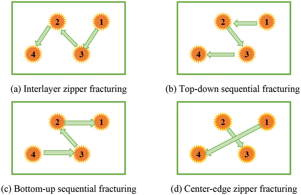
Figure 11: Schematic diagram of the fracturing sequence program
Numerical simulations were conducted to evaluate the performance of the four proposed zipper fracturing sequences. The simulations utilized the previously determined fracturing design parameters and employed stimulated reservoir volume (SRV) as the primary metric for evaluating fracturing effectiveness. The simulated fracture geometries for the four fracturing sequences are presented in Fig. 12. Results indicate that interlayer stress shadowing effects influence fracture propagation direction in all scenarios. Wells 1 and 2 exhibit a downward bias in fracture growth, while Wells 3 and 4 show an upward bias. This vertically asymmetric fracture growth ultimately limits lateral fracture extent. To quantify the degree of stress shadowing effects, a vertical asymmetry factor (VAF) was defined as the ratio of fracture half-height on the side closest to the adjacent layer (h) to the total fracture height (H), as depicted in Fig. 13. A lower VAF value indicates a lesser degree of stress shadowing effects. Fracturing effectiveness was further assessed by comparing the stimulated reservoir volume (SRV) generated by each sequence.
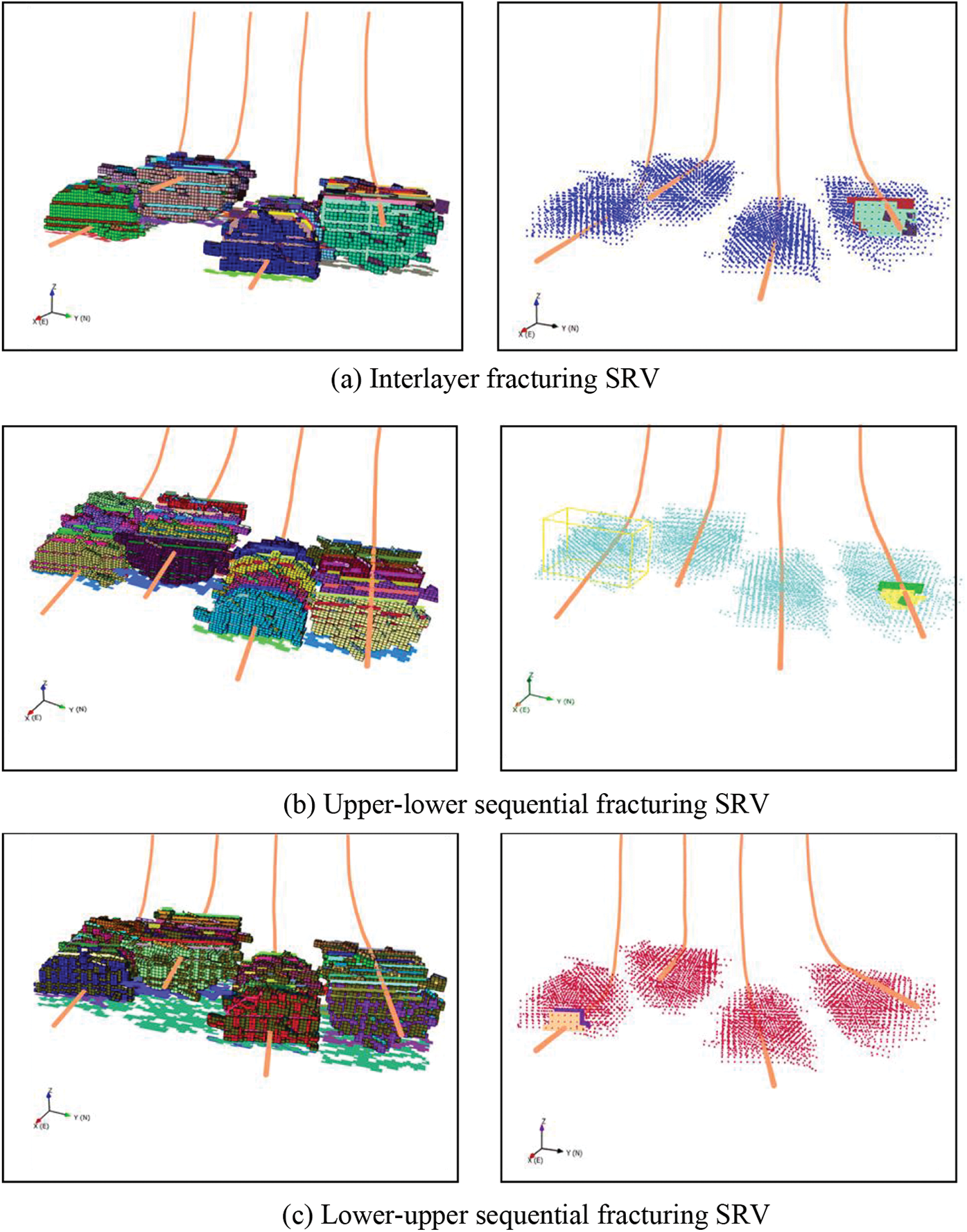
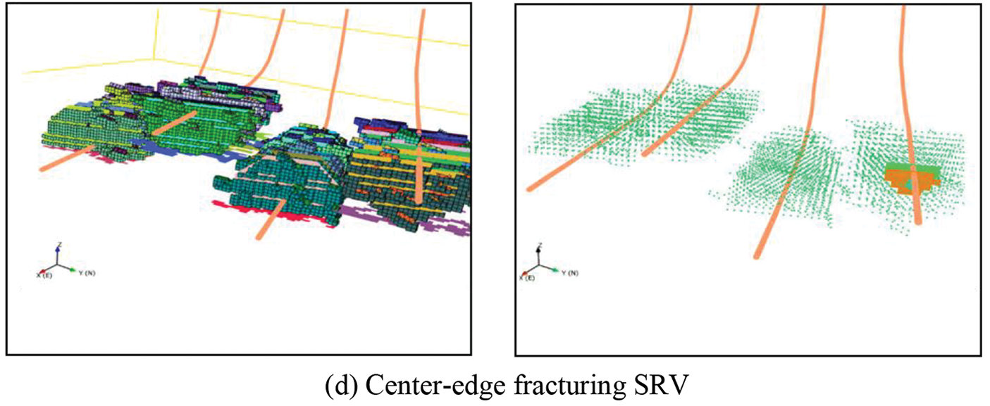
Figure 12: Stimulated reservoir volume for different fracturing sequences
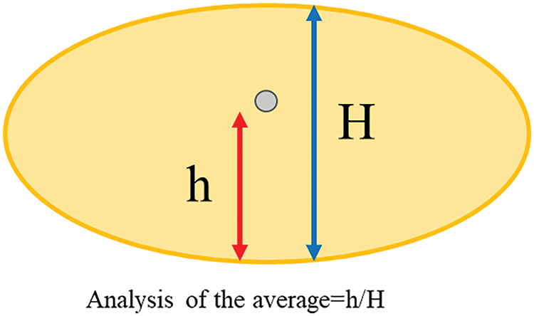
Figure 13: Schematic Diagram of VAF for cubic fracturing
Analysis of the average VAF (Fig. 14) and for each fracturing sequence reveals that the center-edge zipper fracturing scheme exhibits the lowest average VAF (0.71) and an average fracture height of 54.1 m. The remaining sequences show higher VAF values (0.75–0.78) and average fracture heights ranging from 53.8 to 58.1 m. The lower VAF observed for the center-edge sequence suggests it effectively mitigates stress shadowing effects, enabling more extensive lateral fracture propagation. The center-edge fracturing sequence also generated the largest SRV (486,194 m3) compared to the other three sequences (428,496, 476,674, and 470,661 m3). This enhanced SRV can be attributed to the reduced stress shadowing effects achieved by simultaneously fracturing two sets of wells (2–3 and 1–4) separated by a significant lateral distance (>300 m). In contrast, the interlayer, top-down, and bottom-up sequences involve fracturing adjacent wells in close succession, leading to more pronounced stress shadowing, promoting fracture height growth at the expense of lateral extent.
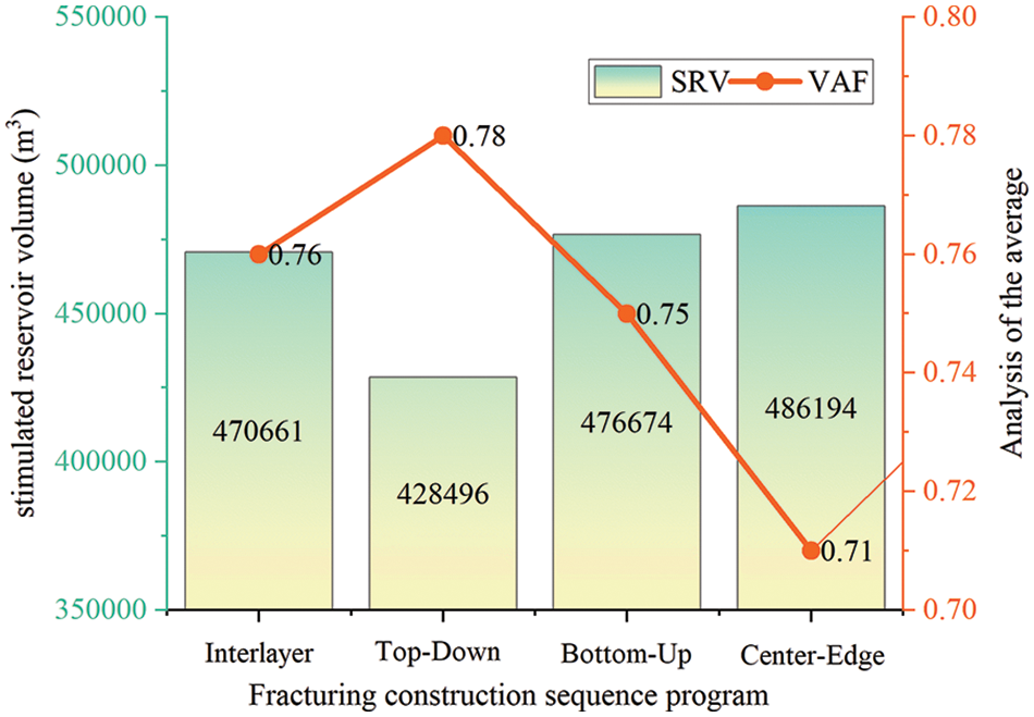
Figure 14: SRV and VAF for different process scenarios
(1) This study presents a comprehensive workflow for designing and optimizing hydraulic fracturing treatments in multilayers and multiwells networks within the Junggar Basin. The workflow integrates multilayer geological modeling, reservoir characterization, geomechanical modeling, fracture propagation simulation, and a dual sweet spot evaluation method to optimize well placement and hydraulic fracturing sequence.
(2) Given the stacked reservoir properties, a multilayer and multiwells network placement can be introduced to maximize reservoir production. The in-situ stress differences at different layers, coupled with the dual sweet spot model, can guide the horizontal wells trajectory design, enhancing the probability of encountering high-quality reservoir sections and obtaining optimal fracture height containment and inter-layer communication strategies.
(3) To mitigate interlayer stress shadowing effects while maximizing reservoir contact, a staggered well placement pattern, incorporating an optimized asymmetric well spacing design, was implemented. This design utilizes 200 m spacing between wells in the upper layer and 250 m spacing in the lower layer. The largest stimulated reservoir volume (SRV) under this type of well placement of 73,082 m3, representing a 65.42% increase compared to 100 m spaced wells. Four zipper fracturing sequences were evaluated using numerical simulation, employing the vertical asymmetry factor (VAF) to quantify stress shadowing. The center-edge fracturing sequence exhibited the lowest VAF (0.71), indicating minimal stress shadowing effects and promoting optimal lateral fracture growth (average fracture height: 54.1 m). The remaining sequences yielded higher VAF values (0.75–0.78) and greater average fracture heights (53.8–58.1 m). The center-edge sequence also generated the largest stimulated reservoir volume (SRV) (486,194 m3), outperforming the other sequences (428,496, 476,674, and 470,661 m3) and demonstrating a 13% increase in SRV compared to the least favorable bottom-up sequence.
(4) The findings of this study regarding the optimization of hydraulic fracturing in a multilayer and multiwells network within the Junggar Basin are promising. However, direct application to other reservoirs requires careful consideration of varying geological and geomechanical characteristics. Factors such as reservoir thickness, lateral extent, stress regime, and rock properties can significantly influence optimal well spacing, placement, and fracturing sequence. While the integrated workflow presented offers a valuable framework, reservoir-specific adjustments are crucial. Future research should focus on comparative studies across diverse reservoir types, sensitivity analyses of key parameters, and field validation to establish broader applicability and refine guidelines for adapting this approach to different geological settings.
Acknowledgement: None.
Funding Statement: This work has been financially supported by the National Natural Science Foundation of China (51704324, 52374027) and Shandong Natural Science Foundation of China (ZR2022ME025, ZR2023ME158).
Author Contributions: The authors confirm contribution to the paper as follows: study conception and design: Xian Shi, Yuanyuan Yang; data collection: Na An, Teng Zhang; analysis and interpretation of results: Cheng Ji, Yujie Yan; draft manuscript preparation: Yuanyuan Yang. All authors reviewed the results and approved the final version of the manuscript.
Availability of Data and Materials: Due to the nature of this research, participants of this study did not agree for their data to be shared publicly, so supporting data is not available.
Ethics Approval: Not applicable.
Conflicts of Interest: The authors declare that they have no conflicts of interest to report regarding the present study.
References
1. K. Wu, “Numerical modeling of complex hydraulic fracture development in unconventional reservoirs,” Ph.D. dissertation, The Univ. of Texas at Austin, Austin, 2014. [Google Scholar]
2. J. He et al., “Formation damage mitigation mechanism for coalbed methane wells via refracturing with fuzzy-ball fluid as temporary blocking agents,” J. Nat. Gas Sci. Eng., vol. 90, no. 5, Jun. 2021, Art. no. 103956. doi: 10.1016/j.jngse.2021.103956. [Google Scholar] [CrossRef]
3. X. Shi, H. Xu, M. Che, C. Xiao, H. Ni and Q. Gao, “Investigations of fracture behavior and pore structure change in pulse fracturing for cement block,” Int. J. Rock Mech. Min. Sci., vol. 166, no. 5, Jun. 2023, Art. no. 105366. doi: 10.1016/j.ijrmms.2023.105366. [Google Scholar] [CrossRef]
4. C. Xiao, S. Zhang, X. Ma, T. Zhou, and X. Li, “Surrogate-assisted hydraulic fracture optimization workflow with applications for shale gas reservoir development: A comparative study of machine learning models,” Nat. Gas Ind. B, vol. 9, no. 3, pp. 219–231, Jun. 2022. doi: 10.1016/j.ngib.2022.03.004. [Google Scholar] [CrossRef]
5. X. Shi, Y. Yang, X. Kong, Q. Gao, B. Guo and Y. Xu, “Experimental study of hydraulic fracture propagation with multi-cluster in-plane perforations in a horizontal well,” Pet. Sci., vol. 125, no. 3, Apr. 2024, Art. no. 359. doi: 10.1016/j.petsci.2024.04.006. [Google Scholar] [CrossRef]
6. N. Stegent, A. Wagner, C. Stringer, R. Tompkins, and N. Smith, “Engineering approach to optimize development strategy in the oil segment of the eagle ford shale: A case study,” SPE Prod. Oper., vol. 28, no. 3, pp. 226–234, Jun. 2013. doi: 10.2118/158846-PA. [Google Scholar] [CrossRef]
7. P. Pankaj, P. Shukla, P. Kavousi, and T. Carr, “Determining optimal well spacing in the Marcellus shale: A case study using an integrated workflow,” presented at the SPE Argentina Explor. Prod. Unconv. Resour. Symp., Neuquen, Argentina, Aug. 14–16, 2018, SPE-191862-MS. [Google Scholar]
8. Q. Lei et al., “Shale oil and gas exploitation in China: Technical comparison with US and development suggestions,” (in ChinesePet. Explor. Dev., vol. 50, no. 4, pp. 944–954, Aug. 2023. doi: 10.1016/S1876-3804(23)60440-9. [Google Scholar] [CrossRef]
9. D. Shin and D. Popovich, “Optimizing vertical and lateral spacing of horizontal wells in Permian Basin stacked bench developments,” presented at the Unconv. Res. Technol. Conf., Austin, TX, USA, Jul. 24–26, 2017, URTEC-2669025-MS. [Google Scholar]
10. K. Srinivasan et al., “Long term development implications of parent-child interactions in unconventional reservoirs,” presented at the ADIPEC, Oct. 2–5, 2023, SPE-216365-MS. [Google Scholar]
11. F. Alimahomed et al., “Stacked pay pad development in the Midland Basin,” presented at the SPE Liquids-Rich Basins Conf.-North Am., Midland, TX, USA, Sep. 13–14, 2017, SPE-187496-MS. [Google Scholar]
12. F. Alimahomed, R. Malpani, R. Jose, C. Defeu, E. Arteaga, and E. Haddad, “Development of the stacked pay in the Delaware basin, Permian basin,” presented at the SPE/AAPG/SEG Unconv. Res. Technol. Conf., Houston, TX, USA, Jul. 23–25, 2018, URTEC-2875581-MS. [Google Scholar]
13. H. Liu et al., “A comparative analysis on the fracture complexity in different fracking patterns of shale gas “well factory,” (in ChineseNat. Gas Ind., vol. 38, no. 12, pp. 70–76, Dec. 2018. doi: 10.3787/j.issn.1000-0976.2018.12.008. [Google Scholar] [CrossRef]
14. J. Thompson, N. Franciose, M. Schutt, K. Hartig, and J. McKenna, “Tank development in the Midland Basin, Texas: A case study of super-charging a reservoir to optimize production and increase horizontal well densities,” presented at the SPE/AAPG/SEG Unconv. Res. Technol. Conf., Houston, TX, USA, Jul. 23–25, 2018, URTEC-2902895-MS. [Google Scholar]
15. J. Wang et al., “A new method for evaluating tridimensional development effect of shale gas horizontal wells based on complex fracture network simulation: A case study of Longmaxi Formation shale gas in the southern Sichuan Basin,” (in ChineseNat. Gas Ind., vol. 42, no. 8, pp. 175–189, Apr. 2022. doi: 10.3787/j.issn.1000-0976.2022.08.014. [Google Scholar] [CrossRef]
16. G. Li, Z. Wu, Z. Li, Q. Chen, C. Xian and H. Liu, “Optimal selection of unconventional petroleum sweet spots inside continental source kitchens and actual application of three-dimensional development technology in horizontal wells: A case study of the Member7 of Yanchang Formation in Ordos Basin,” (in ChineseActa Petrolei Sinica, vol. 42, no. 6, pp. 736–750, Jun. 2021. doi: 10.7623/syxb202106004. [Google Scholar] [CrossRef]
17. K. Gakhar et al., “Engineered approach for multi-well pad development in eagle ford shale,” presented at the Unconv. Res. Technol. Conf., San Antonio, TX, USA, Aug. 1–3, 2016, URTEC-2431182-MS. [Google Scholar]
18. P. Kaufman, M. McClure, N. Franciose, S. Owens, F. Srur and D. Russell, “Optimizing completions in tank style development,” presented at the SPE/AAPG/SEG Unconv. Res. Technol. Conf., Denver, CO, USA, Jul. 22–24, 2019, URTEC-2019-608. [Google Scholar]
19. A. Damani, K. Kanneganti, and R. Malpani, “Sequencing hydraulic fractures to optimize production for stacked well development in the delaware basin,” presented at the Unconv. Res. Technol. Conf., Jul. 20–22, 2020, URTEC-2020-3272. [Google Scholar]
20. I. Gupta, C. Rai, D. Devegowda, and C. H. Sondergeld, “Fracture hits in unconventional reservoirs: A critical review,” SPE J., vol. 26, no. 1, pp. 412–434, Feb. 2021. doi: 10.2118/203839-PA. [Google Scholar] [CrossRef]
21. Y. Zhang, C. J. Okere, and G. Su, “Effect of loading rates on accurate in-situ stress determination in different lithologies via Kaiser effect,” Arab. J. Geosci., vol. 14, no. 14, Jul. 2021, Art. no. 1304. doi: 10.1007/s12517-021-07674-3. [Google Scholar] [CrossRef]
22. B. Lu, C. Hu, and J. Ma, “Influencing factors and countermeasures of inter-well interference of fracturing horizontal wells in Nanchuan shale gas field,” (in ChinesePet. Reservoir Eval. Dev., vol. 13, no. 3, pp. 330–339, Jan. 2023. doi: 10.13809/j.cnki.cn32-1825/te.2023.03.008. [Google Scholar] [CrossRef]
Cite This Article
 Copyright © 2024 The Author(s). Published by Tech Science Press.
This work is licensed under a Creative Commons Attribution 4.0 International License , which permits unrestricted use, distribution, and reproduction in any medium, provided the original work is properly cited.


 Submit a Paper
 Propose a Special lssue
 View Full Text
 Download PDF
 Downloads
 Citation Tools