 Open Access
ARTICLE
Thermodynamic, Economic, and Environmental Analyses and Multi-Objective Optimization of Dual-Pressure Organic Rankine Cycle System with Dual-Stage Ejector
1 Yingkou Institute of Technology, School of Mechanical and Power Engineering, Yingkou, 115014, China
2 Liaoning Technical University, School of Mechanical Engineering, Fuxin, 123000, China
3 CNPC Second Construction Co., Ltd., Petrochina Lanzhou Petrochemical Company, Lanzhou, 730060, China
4 China Power Construction Group Shandong Power Construction First Engineering Co., Ltd., Jinan, 250000, China
* Corresponding Author: Guowei Li. Email:
Energy Engineering 2024, 121(12), 3843-3874. https://doi.org/10.32604/ee.2024.056195
Received 16 July 2024; Accepted 09 September 2024; Issue published 22 November 2024
Abstract
A novel dual-pressure organic Rankine cycle system (DPORC) with a dual-stage ejector (DE-DPORC) is proposed. The system incorporates a dual-stage ejector that utilizes a small amount of extraction steam from the high-pressure expander to pressurize a large quantity of exhaust gas to perform work for the low-pressure expander. This innovative approach addresses condensing pressure limitations, reduces power consumption during pressurization, minimizes heat loss, and enhances the utilization efficiency of waste heat steam. A thermodynamic model is developed with net output work, thermal efficiency, and exergy efficiency (Wnet, ηt, ηex) as evaluation criteria, an economic model is established with levelized energy cost (LEC) as evaluation index, an environmental model is created with annual equivalent carbon dioxide emission reduction (AER) as evaluation parameter. A comprehensive analysis is conducted on the impact of heat source temperature (TS,in), evaporation temperature(T2), entrainment ratio (Er1, Er2), and working fluid pressure (P5, P6) on system performance. It compares the comprehensive performance of the DE-DPORC system with that of the DPORC system at TS,in of 433.15 K and T2 of 378.15 K. Furthermore, multi-objective optimization using the dragonfly algorithm is performed to determine optimal working conditions for the DE-DPORC system through the TOPSIS method. The findings indicate that the DE-DPORC system exhibits a 5.34% increase in Wnet and ηex, a 58.06% increase in ηt, a 5.61% increase in AER, and a reduction of 47.67% and 13.51% in the heat dissipation of the condenser and LEC, compared to the DPORC system, highlighting the advantages of this enhanced system. The optimal operating conditions are TS,in = 426.74 K, T2 = 389.37 K, Er1 = 1.33, Er2 = 3.17, P5 = 0.39 MPa, P6 = 1.32 MPa, which offer valuable technical support for engineering applications; however, they are approaching the peak thermodynamic and environmental performance while falling short of the highest economic performance.Keywords
Nomenclature
| ORC | Organic Rankine Cycle |
| DPORC | Dual-pressure ORC system |
| DE-DPORC | Dual-pressure ORC system with a two-stage ejector |
| LEC | Levelized Energy Cost |
| CEPCI | Chemical Engineering Plant Cost Index |
| AER | Annual Emission Reduction |
| CRF | Capital Recovery Factor |
| GWP | Global Warming Potential |
| ODP | Ozone Depletion Potential |
| TOPSIS | Technique for Order Preference by Similarity to an Ideal Solution |
| a | Extraction fraction |
| A | Heat transfer area (m2) |
| B | Correction factor |
| C | Cost rate ($) |
| E | Exergy rate (kW) |
| Er | Entrainment ratio |
| F | Conversion factors |
| h | Specific enthalpy (kJ/kg) |
| i | Interest rate (%) |
| k | Heat transfer coefficient (W/(m2·K)) |
| K | Correction factor |
| m | Mass flow rate (kg/s) |
| M | Mass (kg) |
| n | Service life (years) |
| N | Annual operation hours (h) |
| p | Pressure (MPa) |
| Q | Heat transfer rate (kW) |
| T | Temperature (K) |
| ΔT | Temperature difference (K) |
| v | Velocity |
| W | Power (kW) |
| η | Efficiency |
| 1–17 | State points |
| S | Waste steam |
| net | Net |
| Eva | Evaporator |
| HT | High-pressure expander |
| Eje | Ejector |
| Reg | Regenerator |
| LT | Low-pressure expander |
| Con | Condenser |
| P | Working fluid pump |
| CO2 | Carbon dioxide |
| ex | Exergy |
| ma | Manufacture |
| FP | Fossil fuel power generation |
The industrial production process consumes a significant amount of energy, resulting in the generation of substantial waste heat resources totaling 340 million tons of standard coal [1,2]. Therefore, the utilization of industrial waste heat is a crucial aspect of energy conservation and emission reduction, as well as an important means to address the relative shortage of energy [3,4]. Approximately 46% of these waste heat resources are high-grade, with temperatures exceeding 400°C. Currently, there is relatively advanced technology for recovering high-temperature waste heat efficiently. The remaining 54% consists of medium- and low-grade waste heat resources below 400°C; however, the technology for recovering low-temperature waste heat is not yet mature, leading to a significant portion being released into the environment and resulting in substantial energy wastage [5,6]. Hence, it holds great practical significance to investigate the utilization technology for medium- and low-grade waste heat.
Among the various medium- and low-grade waste heat resources, steam waste heat constitutes approximately 21% and possesses the advantages of cleanliness, safety, ease of storage, and high latent heat value [7,8], thus warranting attention. The Organic Rankine Cycle (ORC) power generation technology is capable of converting medium- and low-grade waste heat steam into high-grade electric energy. Due to its flexibility, safety features, and low maintenance costs [9,10], ORC has been extensively researched and implemented in industrial sectors such as engine waste heat and flue gas waste heat [11–14], rendering it one of the most promising technologies for waste heat recovery.
The dual-pressure ORC system (DPORC) [15] has garnered significant attention in the realm of ORC power generation systems due to its exceptional efficiency in producing high levels of electrical power, thus making it a subject of extensive research and study. Wang et al. [16] conducted a comparative analysis of the performance between DPORC and ORC utilizing isobutane as the working fluid. The findings revealed that within the heat source temperature range of 100°C to 177.2°C, DPORC exhibited a higher net power output than ORC, with an increasing trend in net power output gain as the heat source temperature decreased. Li et al. [17] observed a significant increase in the net power output of the DPORC system by 21.4%~26.7% compared to the basic ORC, and the DPORC effectively reduced total irreversible loss, particularly to evaporator-induced irreversibility. Based on the DPORC, Feng et al. [18] introduced the concept of a parallel two-stage regenerative DPORC (DTRORC) and conducted an optimization of its thermal economy. The findings indicate that the DTRORC exhibits a 1.75% increase in thermal efficiency compared to the conventional DPORC, along with a 3.5% improvement in exergy efficiency and an additional net power output of 1 kW. Li et al. [19] conducted a comparative analysis of the thermal efficiency between DPORC and supercritical DPORC systems for recovering engine waste heat. The findings revealed that the net output power of the supercritical DPORC system increased by 4.5%, while the total UA decreased by 2.7%. Sun et al. [20] introduced the concept of a regenerative DPORC system and compared it with the basic ORC, demonstrating superior thermal performance in their results. Chen et al. [21] proposed a double-flash geothermal-DPORC system and conducted an assessment of its performance. The analysis demonstrated that the designed system achieves a net power output of 6336.04 kW with an exergy efficiency of 66.70%, and the estimated payback period is 3.48 years, indicating the economic feasibility of the system.
The literature review above indicates that while DPORC enhances the utilization of middle and low-grade waste heat, there is a release of secondary condensing heat during system operation, leading to energy wastage. The implementation of DPORC necessitates two high and low-pressure working fluid pumps, leading to increased power consumption and system cost. Furthermore, due to the constraints of condensing temperature, the performance of working fluid in the turbine is suboptimal. To address the issue of lost condensing heat due to temperature limitations, an injector can be integrated at the turbine tail in an ORC system to effectively utilize turbine exhaust gas. Larbi et al. [22] used an ejector for the refrigeration of ORC turbine exhaust gas to ensure simultaneous power production and refrigeration and incorporated novel thermodynamic parameters to enhance system efficiency. Wu et al. [23] conducted a study on the dynamic response of the ORC combined ejector expansion refrigeration cycle (ORC-EERC), and developed a dynamic model for single and double condenser configurations of the ORC-EERC. The findings indicate that the impact of the ORC subsystem on the refrigeration subsystem is more pronounced in the ORC-EERC system with a single condenser compared to that with a double condenser. Mortazavi et al. [24] proposed a novel ejector-enhanced ORC and two-stage compression refrigeration cycle (EORC-TCRC) combination and conducted a comprehensive energy, exergy, economic, and environmental (4E) analysis. The results indicate that the cooling output power, energy efficiency, and exergy efficiency of the EORC-TCRC system have increased by 220.06 kW, 11.67%, and 17.07% respectively compared to traditional ORC and ejector refrigeration systems. Haghparast et al. [25] conducted a study on the impact of ejector geometry and operational characteristics on ORC output power. The findings indicate that the net power output increases with an increase in ejector area ratio and secondary mass flow rate, while it decreases with an increase in pipe diameter, primary inlet pressure, or primary inlet temperature. Srivastava et al. [26] introduced two novel ejector-enhanced ORCs (EEORC-1 and EEORC-2) and employed three newly developed economic models (M1, M2, and M3) to assess real-world feasibility. The findings indicate that EEORC-1 utilizing R123 exhibits superior performance at a heat source temperature of 70°C, resulting in a maximum net output increase of 18%. Within the framework of the M2 economic model, EEORC-1 demonstrates the highest profit escalation of 7.32%.
Therefore, to solve the limitation of DPORC system to further improve the utilization efficiency of steam waste heat, this paper proposes a novel DPORC system with a dual-stage ejector (DE-DPORC), in which the dual-stage ejector is located at the end of the high-pressure expander of DPORC system to solve the limitation of condensing pressure. The dual-stage ejector uses a small amount of extracted steam from the high-pressure expander to pressurize the large amount of exhaust gas from the high-pressure expander and then enters the low-pressure expander for operation. This pressurization process consumes no electricity and replaces a low-pressure working fluid pump. In addition, the operation of the system involves only one heat release process, thus reducing heat loss.
To further comprehend the technical potential, energy conservation, and emission reduction capabilities, as well as the economic feasibility of the DE-DPORC system, thermodynamic, economic, and environmental models have been established. The impact of heat source temperature, evaporation temperature, entrainment ratio, and working fluid pressure of the dual-stage ejector on system performance is investigated using waste heat steam from a steelmaking converter in Tangshan Ruifeng Steel Group, Chian as the heat source. A comparison of the performance between the DE-DPORC system and the DPORC system under fixed working conditions is conducted. Furthermore, multi-objective optimization of the DE-DPORC system using the Dragonfly algorithm and TOPSIS comprehensive evaluation method is performed to unveil optimal operating parameters for enhanced system performance.
The primary innovations of this paper can be outlined as follows:
• A novel dual-pressure ORC system with a dual-stage ejector is proposed for efficient utilization of steam waste heat.
• A dual-stage ejector is incorporated into the DE-DPORC system to enhance system performance by addressing constraints related to condensing pressure, reducing power consumption of the working fluid pump, and minimizing heat loss during condensation.
• A thorough performance analysis and multi-objective optimization are conducted under diverse operational conditions to enhance the understanding of the DE-DPORC system.
Fig. 1 illustrates the structure of the dual-stage ejector and depicts the variations in pressure and velocity during its operation. The dual-stage ejector consists of two ejectors arranged in series. During operation, the working fluid (5, 6) undergoes expansion into the suction section, leading to an increase in velocity and a decrease in pressure. Upon exiting the nozzle outlet, the working fluid typically attains a supersonic state, generating a region of low pressure at the inlet of the mixing section (7, 11). The injection fluid (4, 10) is introduced into the mixing chamber for amalgamation with the working fluid (8, 12); Subsequently, this mixed fluid enters the diffuser chamber for deceleration and pressurization (9, 13), before ultimately exiting from the ejector (10, 14) [27]. The ejector effectively utilizes a small amount of high-pressure working fluid to elevate the pressure of the ejecting fluid without consuming mechanical energy during operation, thus offering a simpler and more reliable alternative to mechanical supercharging equipment.
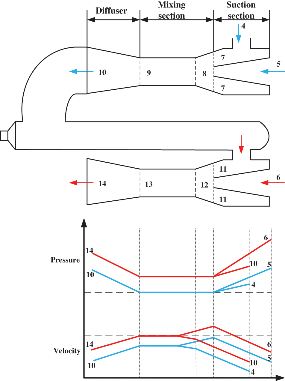
Figure 1: The structure of a dual-stage ejector and the variation trend of pressure and velocity during operation
Figs. 2 and 3 illustrate the diagram and thermal process of the DE-DPORC system. The system comprises an evaporator, a regenerator, high and low-pressure expanders, a dual-stage ejector, a working fluid pump, and a condenser. The operational process is as follows: waste heat steam enters the evaporator to superheat the organic working fluid (Processes 1–3); upon entering the high-pressure expander to do work (Processes 3–4), the outlet pressure of the high-pressure expander is significantly lower than that of conventional back pressure. The exhaust gas from the high-pressure expander serves as the ejecting fluid of the primary ejector (State 4), while the low-pressure gas from the high-pressure expander functions as the working fluid for the primary ejector (State 5). The fluid discharged from the primary ejector is utilized as the ejecting fluid for the secondary ejector (State 10), with high-pressure gas from the high-pressure expander serving as its working fluid (State 6). Following passage through the secondary ejector, the exhaust gas transitions into a medium-pressure and medium-temperature gaseous working fluid (State 14), entering a regenerator to absorb heat from residual heat steam exiting an evaporator (Processes 14–15). Subsequently, it undergoes a work process in a low-pressure expander (Processes 15–16); exhaust gas then enters a condenser and is condensed into liquid form by cooling water (Processes 16–17). After being pressurized by a working fluid pump and returning to an evaporator, this completes one cycle.
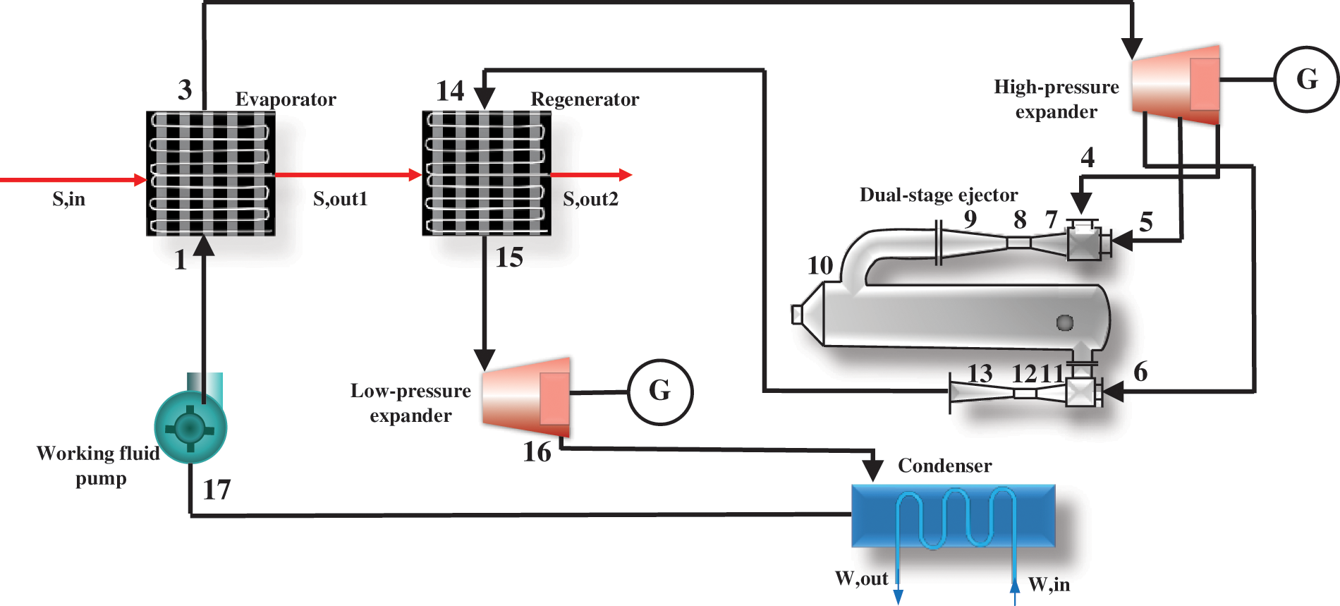
Figure 2: Diagram of the DE-DPORC system
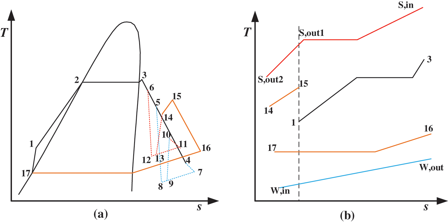
Figure 3: Thermal process and heat transfer of the DE-DPORC system (a) is the thermal process of the DE-DPORC system, and (b) is the heat transfer process of the DE-DPORC system
In the DE-DPORC system, the implementation of a dual-stage ejector serves to mitigate back pressure in the high-pressure expander, thereby enhancing its power output. This design also obviates the need for a low-pressure working fluid pump, resulting in reduced energy consumption and capital investment costs. Furthermore, it minimizes heat loss during the condensation process. Notably, compared to the single-stage ejector, the two-stage ejector is capable of reasonably extracting steam from the high-pressure expander to eject exhaust gas, thereby efficiently controlling pressure drop in each stage of the working fluid and reducing pressure loss. This integration of the two-stage ejector and DPORC system demonstrates a high level of effectiveness.
2.3 Working Fluid and Boundary Conditions of the DE-DPORC System
Under literature [28,29] recommendations, dry fluid R245fa is chosen as the working fluid due to its non-toxic nature, chemical stability, favorable thermodynamic properties, and low greenhouse gas emissions. Table 1 presents the boundary conditions of the DE-DPORC system. The steam waste heat is from the steelmaking converter at Tangshan Ruifeng Steel Group in China. The evaporation temperature, cooling water parameters, equipment efficiency, etc., are determined based on previous studies [30,31]. The working fluid pressure of the ejector, extraction fraction, and entrainment ratio are set according to the characteristics and operating parameters of the DE-DPORC system.

Before delving into the models, the following assumptions are posited:
(1) DE-DPORC system is in a steady state.
(2) Heat dissipation and pressure drop in pipes are deemed to be negligible.
(3) The impact of fluid dynamics and gravitational potential energy is deemed insignificant.
The components of the DE-DPORC system satisfy the mass, energy, and exergy balance equations, as detailed in Table 2.

The levelized energy cost (LEC) serves as a key metric for assessing the economic viability of the DE-DPORC system and can be mathematically represented as
The total purchase cost of the system (Ctotal) encompasses the individual purchase costs of each component, as detailed in Table 3 and adjusted by the chemical engineering plant cost index for year 2023 (CEPCI2023). This can be mathematically represented as

The capital recovery factor (CRF) is
where COM is the operation and maintenance cost of the DE-DPORC system, equivalent to 1% of the overall investment outlay [30]; N is the annual operation hour, 7500 h [32]; ƞg is the generator efficiency, 85% [32]; n is the life cycle, 15 years [32]; i is the interest rate, 2.73% [30]; CEPCI2001 is 397 [32]; CEPCI2023 is 797.9 [33].
The annual equivalent reduction in carbon dioxide (CO2) emissions (AER) is utilized as the environmental assessment index, and can be expressed as
The equivalent CO2 emissions from a 1kW electricity-generating fossil fuel power station is
The equivalent CO2 emissions generated throughout the manufacturing process over the life cycle of a 1kW electricity-generating is
where m represents the mass of greenhouse gas released by the fossil-fuel power station to produce 1 kWh of electricity; F denotes the equivalent CO2 factor converted by the greenhouse gas, as detailed in Table 4. M is the mass of the device, is determined by the calculation equation for system components as presented in Table 5.
3.4 Multi-Objective Optimization Models
The objective functions consist of maximizing the net output power (Wnet), minimizing the levelized energy cost (LEC), and maximizing the annual equivalent reduction in CO2 emissions (AER). The decision variables consist of the steam heat source temperature (TS,in), evaporation temperature (T2), entrainment ratios of the dual-stage ejector (Er1, Er2), and working fluid pressures of the dual-stage ejector (P5, P6). A multi-objective optimization model is then formulated based on these parameters.
In this study, within the MATLAB environment (combined with REFPROP 9.0 software), the dragonfly algorithm [36] is employed for multi-objective optimization. Subsequently, the Pareto frontier is obtained and the technique for order preference by similarity to an ideal solution (TOPSIS) [37] is utilized to select the unique optimal solution. The constraints in the optimization process are considered and addressed as
As the DE-DPORC system is a recent proposal, experimental verification is not feasible. Therefore, the focus of this study is on verifying the key components of the DE-DPORC system–the ejector and ORC system. The operating parameters of the ejector and a comparison between simulation and experimental results [38] are presented in Table 6. It can be observed from Table 6 that, based on the thermodynamic model developed in this study, the simulated outlet pressure of the ejector using MATLAB software (combined with REFPROP 9.0 software) is 381.34 kPa with a relative deviation of 0.24% compared to experimental results. Additionally, Table 7 presents a comparison between simulation and experimental results [39] for the ORC system, demonstrating strong consistency with relative errors ranging from −0.36% to 4.96%. Consequently, this paper provides verified accuracy in both model development and simulation outcomes.


5.1 Performance Comparison between DE-DPORC System and DPORC System
To elucidate the advantages of the proposed DE-DPORC system, the performance of this system is compared with that of the DPORC system. Two systems operate at a steam heat source temperature (TS,in) of 433.15 K and an evaporation temperature (T2) of 378.15 K for the high-temperature evaporator. In the DE-DPORC system, the entrainment ratios for the dual-stage ejectors (Er1, Er2) are set at 3 and 4, respectively, with working fluid pressures (P5, P6) of 0.5 and 1 MPa, respectively. For the DPORC system, evaporation pressure for the low-pressure cycle is determined based on principles governing sufficient utilization of steam waste heat. The parameters for each state point in the two systems are presented in Table 8, from which performance parameters are derived as shown in Table 9. Compared with the DPORC system, although a portion of the working fluid from the high-pressure expander is extracted as the working fluid for the dual-stage ejector in the DE-DPORC system, there is a 15.26% increase in output power of the high-pressure expander (WHT) due to the reduction in outlet pressure. The output power of the low-pressure expander (WLT) experiences a decrease of 7.34% as a result of lower inlet pressure. With only one working fluid pump, the power consumption of the DE-DPORC system (WP) is reduced by 43.22%. Consequently, these parameters contribute to an overall increase in net output power (Wnet) by 5.34% for the DE-DPORC system. The DE-DPORC system undergoes a single condensation process, resulting in a 47.67% reduction in condensation heat dissipation (Qcon). This leads to a 58.06% increase in thermal efficiency (ηt) due to reduced heat transfer of regenerator. The exergy efficiency (ηex) of the DE-DPORC system increases by 5.34% with the rise in Wnet, while the levelized energy cost (LEC) decreases by 13.51%. Additionally, there is a 5.61% increase in equivalent CO2 emission reduction (AER) for the DE-DPORC system.


5.2 Effect of Steam Temperature and Evaporation Temperature on the Performance of the DE-DPORC System
When the entrainment ratios of the dual-stage ejectors (Er1, Er2) are 3 and 4, and the working fluid pressures of the dual-stage ejectors (P5, P6) are 0.4 MPa and 0.8 MPa, respectively, Fig. 4 illustrates the variations in Wnet, ηt, and ηex of the DE-DPORC system to steam temperature (TS,in) and evaporation temperature (T2). Under constant TS,in, Wnet, ηt, and ηex exhibit an initial increase followed by a decrease as T2 rises; When T2 is fixed, Wnet, ηt, and ηex increase as TS,in rises.
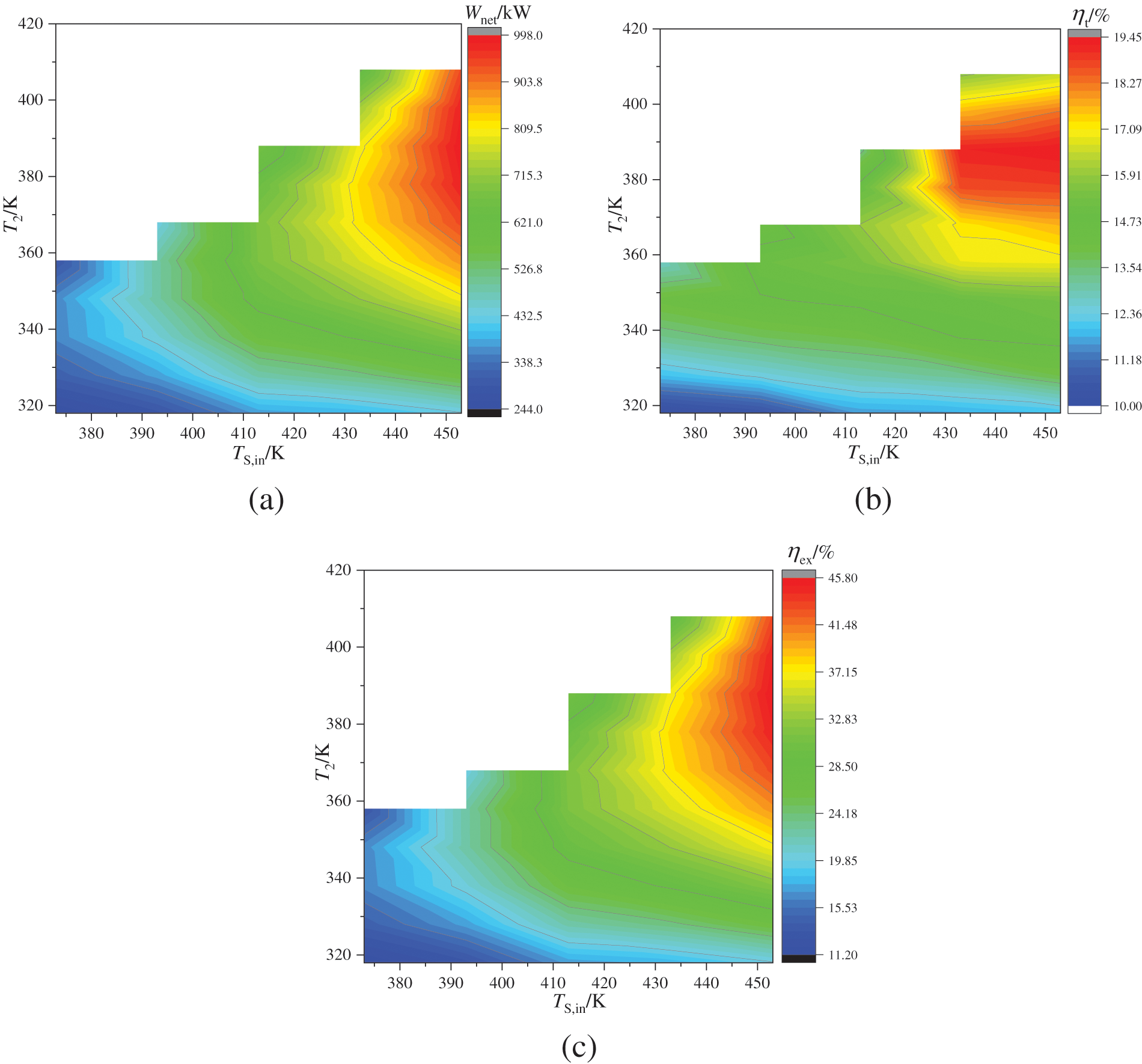
Figure 4: Impact of steam heat source temperature and evaporation temperature on the net output power, thermal efficiency, and exergy efficiency
Wnet is determined by the power output of the high and low-pressure expander (WHT, WLT), as well as the consumption power of the working fluid pump (WP). When TS,in remains constant, an increase in T2 leads to a rise in evaporation pressure (P2) and enthalpy at the inlet of the high-pressure expander (h3). However, this also results in a decrease in the mass flow rate of the working fluid (mwf). While the outlet pressure and extraction pressure of the high-pressure expander remain constant, there is an increase in enthalpy drop for the high-pressure expander but a decrease in mwf. Therefore, under these combined influences, WHT initially increases before decreasing. In the current operational environment, the outlet pressure of the dual-stage ejector (P14) exhibits minimal variation, while the outlet temperature of the working fluid (T15) experiences an increase due to elevated heat source temperatures (TS,out1) in the regenerator. However, WLT is primarily reduced by a decrease in mwf, and WP also decreases with a reduction in mwf. For instance, when TS,in is 453 K and T2 increases from 318 to 418 K, WHT initially rises from 216.12 to 832.95 kW before decreasing to 725.12 kW; WLT decreases from 215.10 to 155.78 kW; and WP decreases from 1.88 to 1.38 kW as illustrated in Fig. 5. Wnet is significantly influenced by WHT and follows a similar trend of change. When T2 is fixed, the mwf and WHT both increase with an increase in TS,in. Additionally, an increase in T15 results in a higher enthalpy at the inlet of the low-pressure expander, leading to an increase in WLT; WP increases as mwf increases. For instance, when T2 is 358 K and TS,in rises from 373 to 453 K, WHT increases from 161.32 to 701.57 kW, WLT increases from 131.14 to 182.18 kW, and WP rises from 1.28 to 1.68 kW. Consequently, there is an overall increase in Wnet due to the increased values of both WHT and WLT.
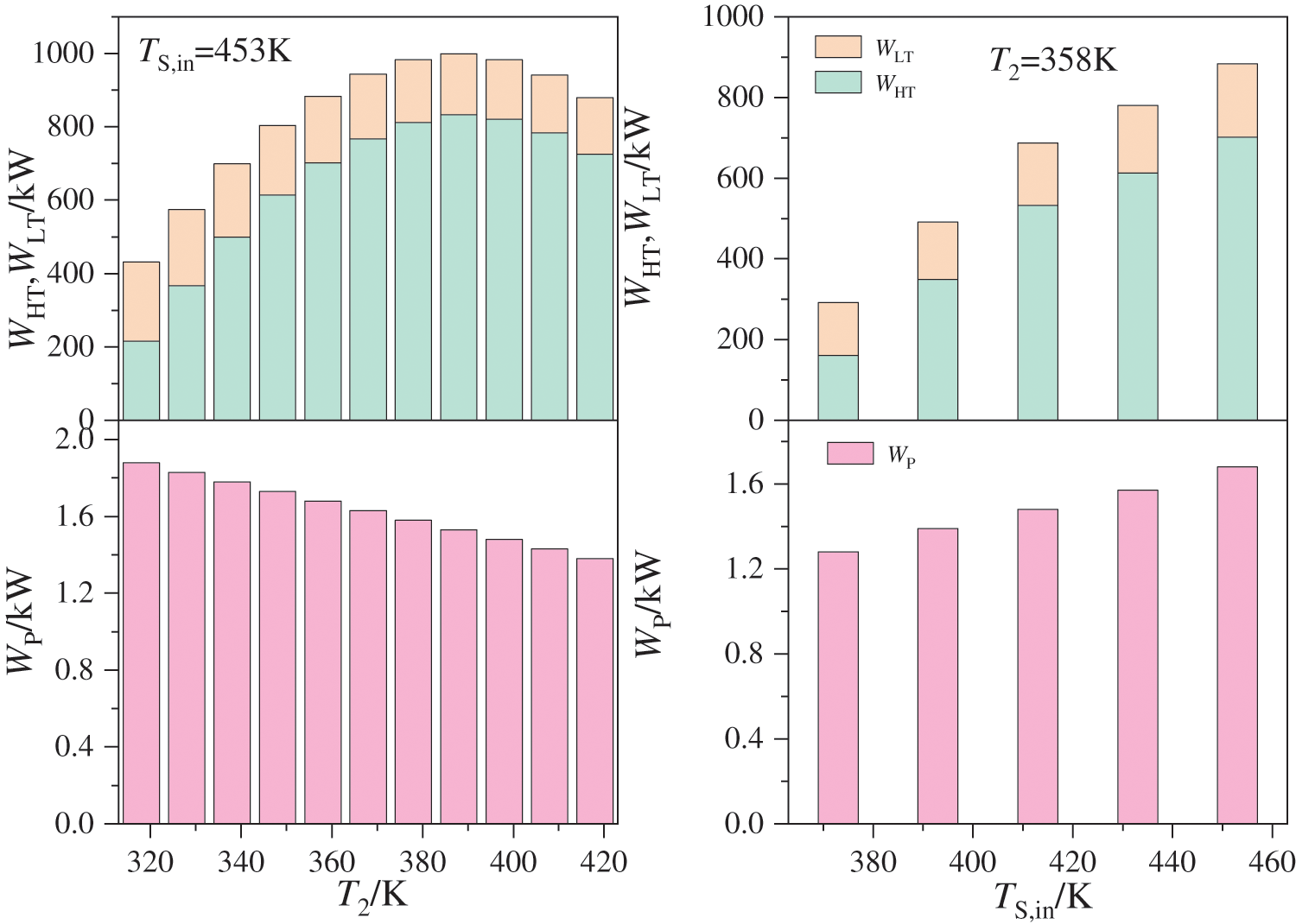
Figure 5: Impact of steam heat source temperature and evaporation temperature on the output power of the high and low-pressure expander, and the consumption power of the working fluid pump
For ηt, it is essential to consider the ratio of the Wnet to the combined heat absorbed by both the evaporator and regenerator. It should be noted that as T2 increases, there is a corresponding increase in heat absorption by the evaporator when maintaining a constant TS,in. Conversely, factors such as a decrease in mwf and an increase in T15 can lead to a slight decrease in heat absorption by the regenerator. While there may be fluctuations in total heat absorption, it is primarily influenced by changes in Wnet. Thus, ηt demonstrates a pattern of initially increasing before subsequently decreasing. When T2 remains constant and TS,in increases, both the heat absorption of the evaporator and regenerator increase. However, the total heat absorption does not increase as much as Wnet, leading to an increase in ηt. In terms of ηex, it is determined by the ratio of Wnet to steam heat source input exergy. When the TS,in is fixed, steam heat source input exergy remains constant, and ηex depends solely on Wnet. When T2 is fixed and TS,in increases, steam heat source input exergy can also increase but at a rate lower than that of Wnet, resulting in an overall increase in ηex.
Fig. 6 illustrates the effects of TS,in and T2 on LEC. When TS,in remains constant, LEC decreases as T2 increases. Conversely, when T2 is held constant, LEC increases with an increase in TS,in. According to Eq. (1), LEC primarily relies on the Wnet and total investment cost. Based on the aforementioned analysis, under constant TS,in, as T2 increases, the evaporator heat absorption rises, and the heat exchange temperature difference decreases, leading to an increase in evaporator heat exchange area and investment cost. Regenerator heat transfer diminishes as the heat transfer temperature difference slightly increases, resulting in a reduction of heat transfer area and investment cost. The investment cost of the high-pressure expander initially increases and then decreases as a result of its output power. The investment costs of the low-pressure expander and the working fluid pump are also impacted by the reduction in their power. The pressure parameter of the dual-stage ejector experiences a slight increase, leading to a corresponding slight increase in its investment cost. A marginal rise in the heat discharge of the condenser results in a minor increase in its investment cost. The overall investment cost is primarily influenced by the investment costs associated with both high and low-pressure expanders. Therefore, when T2 is lower, LEC is affected by an increase in Wnet, resulting in a significant decrease; whereas when T2 is higher, LEC is affected by reductions in total investment cost and Wnet, leading to a slower decrease. When T2 is fixed, the increase in TS,in leads to a corresponding increase in heat transfer affecting the evaporator, reheater, and condenser, resulting in higher investment costs. The power requirements of the high and low-pressure expanders and working fluid pump also increase with TS,in, leading to higher investment costs. Additionally, there is a slight increase in the investment cost of the dual-stage ejector. Consequently, the investment cost of the DE-DPORC system rises, ultimately leading to an increase in LEC.
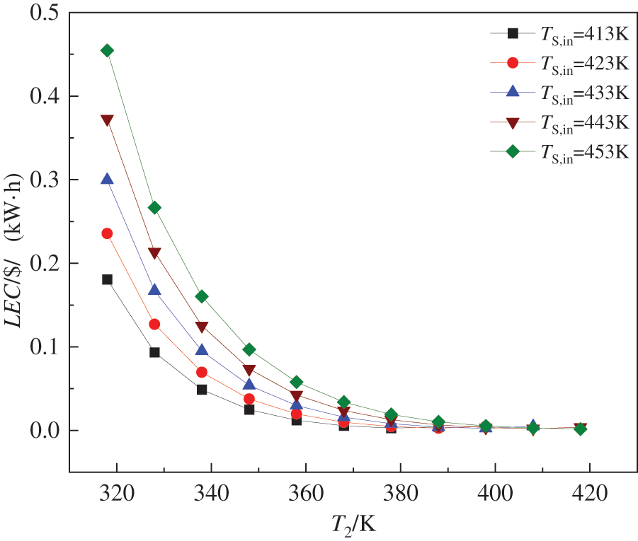
Figure 6: Effects of steam heat source temperature and evaporation temperature on the levelized energy cost
Fig. 7 illustrates the impact of the TS,in and T2 on AER. When TS,in remains constant, AER initially increases and then decreases with the rise in T2, a higher TS,in corresponds to a greater maximum value of AER at T2; When T2 is held constant, AER increases as TS,in rises. This is because AER is contingent upon the reduction in equivalent CO2 emissions during DE-DPORC system power generation and equipment manufacturing processes throughout the life cycle. Under constant TS,in conditions, an increase in T2 leads to a greater evaporator heat transfer area and subsequently an increase in mass. The heat transfer area of the regenerator decreases, leading to a decrease in its mass. The mass of the high-pressure expander initially increases and then decreases as a result of changes in output power. The mass of the low-pressure expander and the working fluid pump is reduced due to their power. There is a slight increase in the mass of the condenser. The total equipment mass first increases and then decreases, with a significant impact on Wnet, resulting in an initial increase followed by a decrease in AER. When T2 remains constant, all equipment mass in the DE-DPORC system increases with an increase in TS,in, but AER is primarily affected by changes in Wnet.
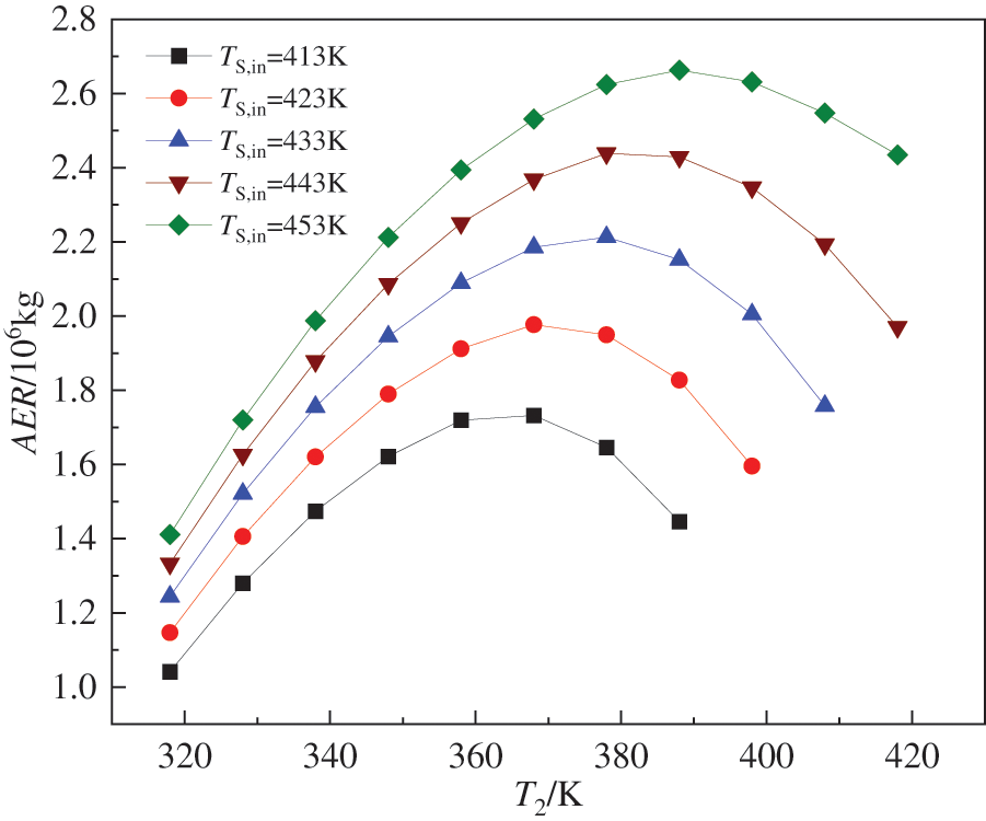
Figure 7: Effects of steam heat source temperature and evaporation temperature on the equivalent CO2 emission reduction
Upon analysis, it is evident that the increase in TS,in primarily results in an increase in the mass flow rate of the working fluid within the system, subsequently leading to increases in Wnet, ηt, ηex, LEC, and AER. The rise in T2 corresponds to an increase in the inlet state parameters of both high- and low-pressure expanders; however, this also causes a decrease in the mass flow rate of the working fluid within the system. As a result, Wnet, ηt, ηex, and AER initially experience an increase followed by a decrease while LEC decreases. In comparison to TS,in changes, DE-DPORC system performance demonstrates greater sensitivity towards alterations in T2 with higher heat source temperatures exhibiting stronger sensitivity. Under these operating conditions for practical engineering applications, optimal thermodynamic and environmental performance for DE-DPORC systems is achieved at TS,in = 453.15 K and T2 = 388.15 K. Economic performance peaks when TS,in = 453.15 K and T2 = 418.15 K; however, this condition necessitates higher equipment pressure requirements than the former scenario.
5.3 Effect of Entrainment Ratios of the Dual-Stage Ejector on the Performance of the DE-DPORC System
The entrainment ratios, defined as the ratio of the mass flow rate of the ejecting fluid to the mass flow rate of the working fluid, are crucial parameters for assessing ejector performance. In this study, the entrainment ratios of the dual-stage ejectors (Er1, Er2) are adjusted by manipulating the proportion of high and low-pressure extraction steam from the high-pressure expander (a5, a6). As depicted in Fig. 8, variations in Er1 and Er2 with changes in a5 and a6 are observed at a TS,in of 433 K, an T2 of 388 K, and working fluid pressures for the dual-stage ejectors (P5, P6) at 0.4 MPa and 0.9 MPa, respectively. Under constant a6 conditions, Er1 decreases while Er2 increases with increasing a5; thus indicating an inverse relationship between Er1 and Er2 under these operating conditions. Conversely, when holding the a5 constant, both Er1 and Er2 decrease with increasing a6; demonstrating that there is a proportional relationship between Er1 and Er2 under these conditions.
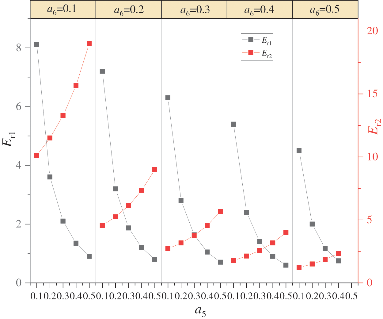
Figure 8: Effects of extraction steam from the high-pressure expander on the entrainment ratios of the dual-stage ejector
The variation in Wnet of the DE-DPORC system with the different Er1 and Er2 above is illustrated in Fig. 9. It is observed that, under varying a6 conditions, as Er1 decreases and Er2 increases, Wnet initially rises before subsequently declining. This indicates the existence of the optimal Er1 and Er2 which maximizes Wnet. Due to the decrease in Er1, which results in a decrease in mass flow rate of exhaust gas (m4) and an increase in mass flow rate of low-pressure extraction steam (m5), the output power of the high-pressure expander (WHT) gradually decreases. Conversely, an increase in Er2 leads to an increase in mass flow rate at the outlet of the primary ejector (m10) and a decrease in mass flow rate of high-pressure extraction steam (m6), causing continuous increases in the outlet temperatures of primary ejector and secondary ejector (T10, T14). Consequently, the output work of the low-pressure expander (WLT) increases. Thus, Wnet initially increases and then decreases. Specifically, when a6 = 0.3, Er1 = 1.63, and Er2 = 3.76, Wnet reaches its maximum value at 1210.14 kW for the DE-DPORC system.
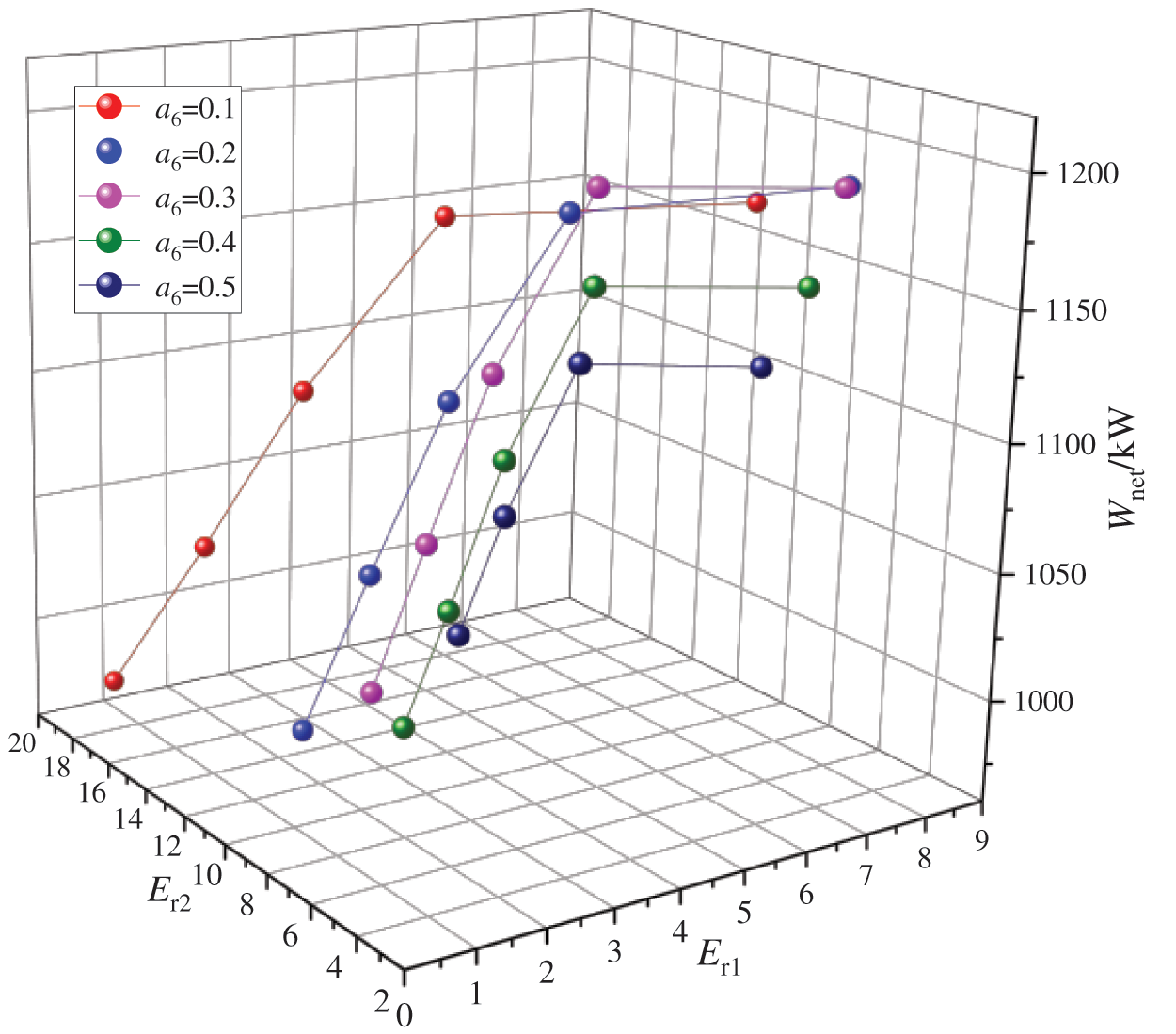
Figure 9: Effects of entrainment ratios of the dual-stage ejector on the net output power
Fig. 10 illustrates the variations in ηt and ηex of the DE-DPORC system at different Er1 and Er2. As Er1 decreases and Er2 increases, there is a gradual decline in ηt, while ηex initially rises before subsequently declining. The reasons are that the TS,in and T2 remain constant, the heat absorption of the evaporator and the input exergy from the heat source can be stabilized. As Er1 decreases and Er2 increases, there is an increase in outlet pressure and temperature for the two-stage ejector, leading to a subsequent rise in heat absorption upon entering the regenerator. This results in an overall increase in total system heat absorption, consequently reducing ηt due to increased heat absorption. ηex is solely dependent on Wnet, thus exhibiting a similar trend as Wnet. When a6 = 0.3, Er1 = 6.30, Er2 = 2.70, the maximum ηt is 21.70%; When a6 = 0.3, Er1 = 1.63, Er2 = 3.76 leads to achieving a maximum ηex value of 43.95%.
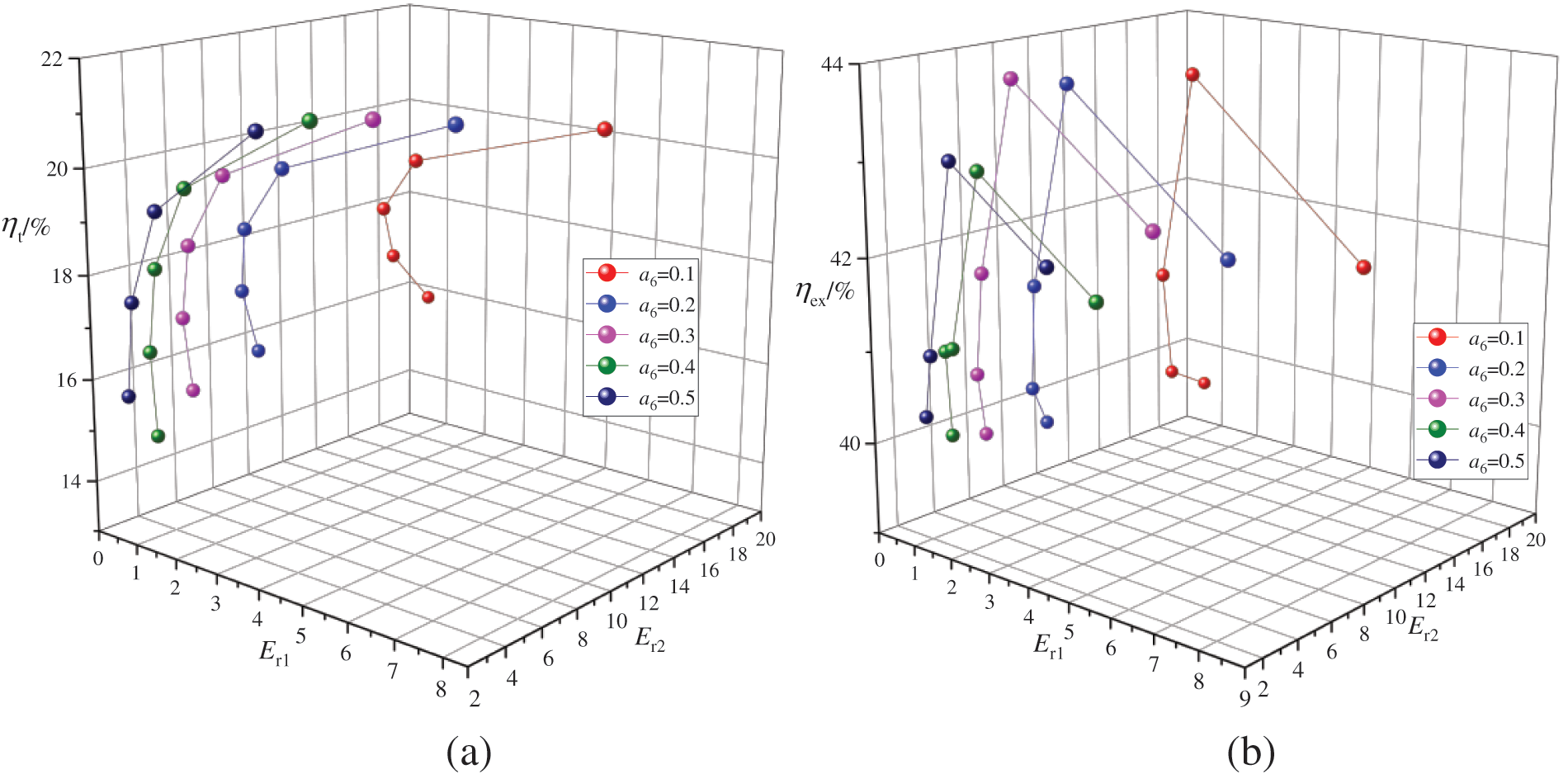
Figure 10: Effects of entrainment ratios of the dual-stage ejector on the thermal efficiency and exergy efficiency (a) shows the effects of entrainment ratios of the dual-stage ejector on the thermal efficiency, (b) shows the effects of entrainment ratios of the dual-stage ejector on the exergy efficiency
Fig. 11 illustrates the LEC under varying Er1 and Er2. It is observed that, under different a6 conditions, LEC increases with decreasing Er1 and increasing Er2. Based on the aforementioned analysis, in this operational scenario, the heat absorption of the evaporator and the work consumption of the working fluid pump remain constant, leading to a fixed investment cost. The output power of the high-pressure expander decreases, resulting in reduced investment costs; meanwhile, there is an increase in investment costs for the low-pressure expander, regenerator, and condenser. The overall investment cost (Ctotal) is primarily influenced by the initial investment in high-pressure expander, followed by the costs associated with low-pressure expander, regenerator, and condenser. This results in a trend of decreasing followed by increasing. As Wnet initially increases and then decreases, LEC gradually rises with the decrease of Er1 and the increase of Er2 due to their influence on Wnet and Ctotal. When a6 = 0.2, Er1 = 7.20, Er2 = 4.56, the LEC reaches a minimum of 0.06 $/(kW·h).
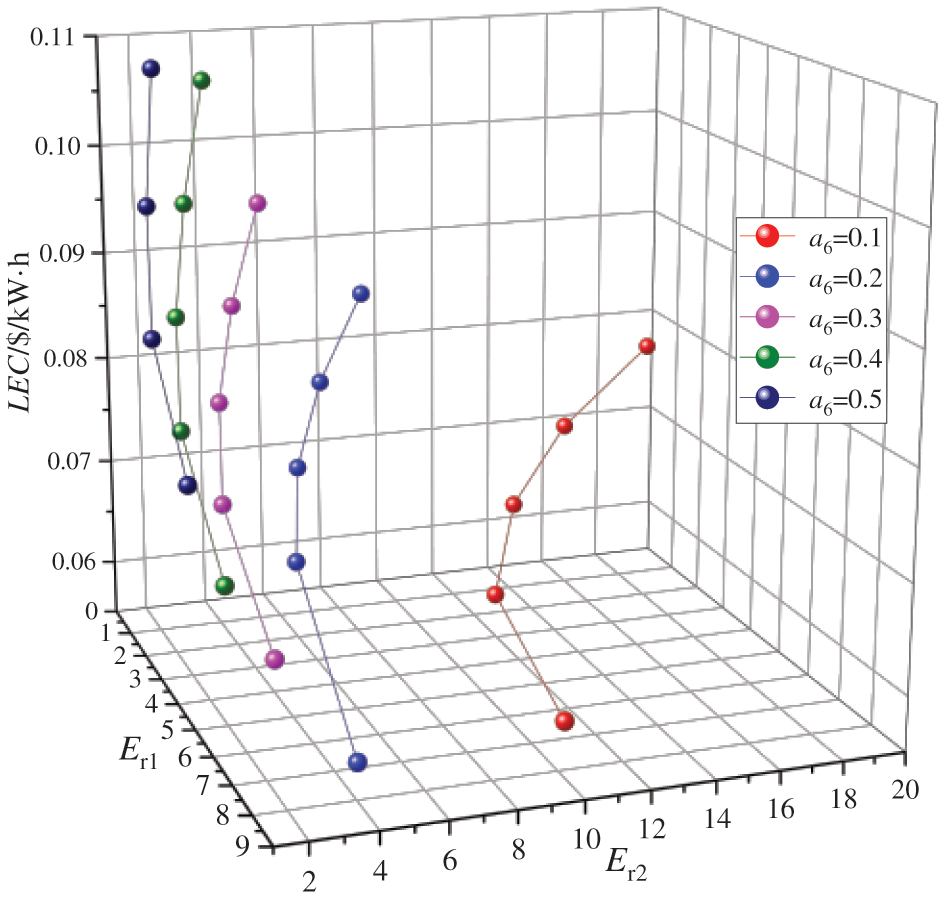
Figure 11: Effects of entrainment ratios of the dual-stage ejector on the levelized energy cost
Fig. 12 illustrates the variations in AER at different Er1 and Er2. As Er1 decreases and Er2 increases, AER initially rises before declining. This phenomenon can be attributed to the impact of Wnet on the equivalent CO2 emission reduction during DE-DPORC system power generation, which initially increases and then decreases with the decrease in Er1 and increase in Er2. Additionally, changes in heat exchange and power of each equipment affect the equivalent CO2 emitted during system construction, resulting in a trend of initial decrease followed by an increase. Consequently, under the influence of these two factors, AER exhibits an initial increase followed by a decrease, mirroring the trend observed for Wnet but with a different corresponding maximum point. Specifically, when a6 = 0.1, Er1 = 2.10, Er2 = 13.28, the DE-DPORC system achieves a maximum AER value of 3.17 × 10⁶ kg.
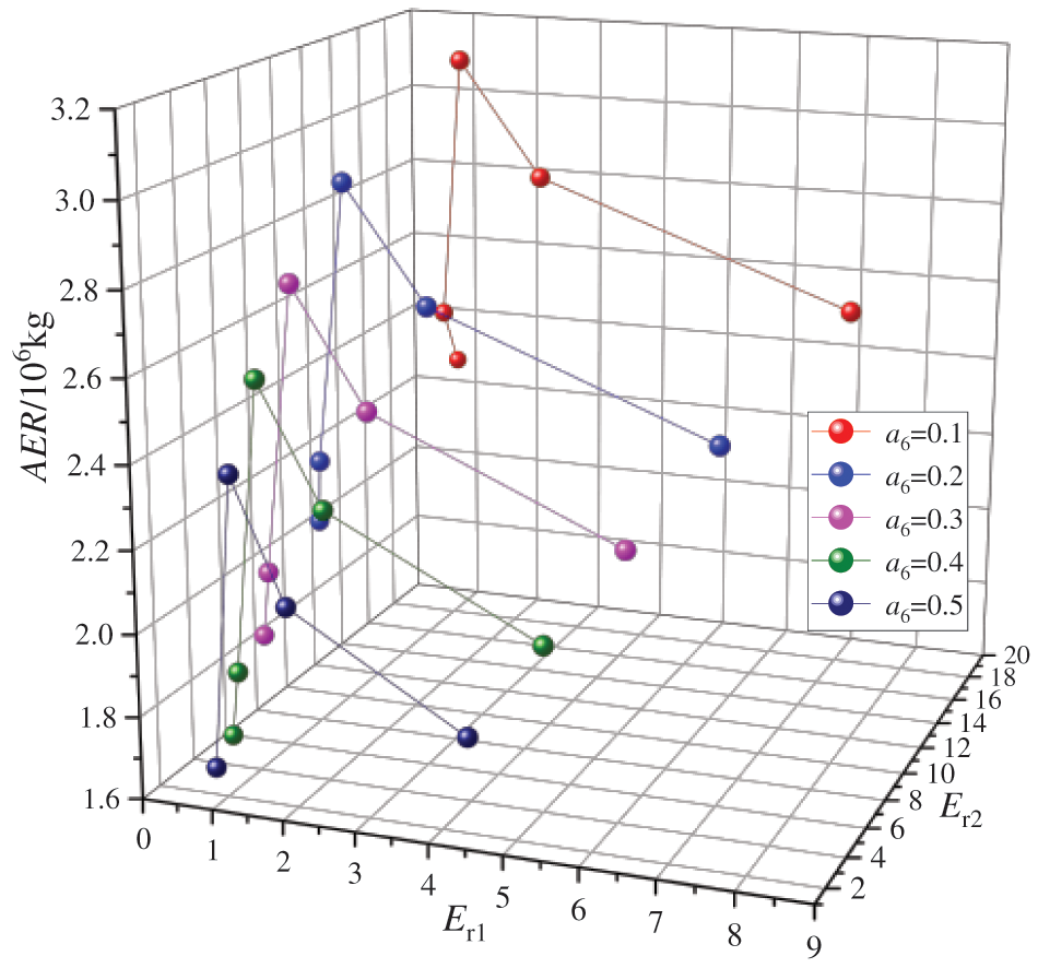
Figure 12: Effects of entrainment ratios of the dual-stage ejector on the equivalent CO2 emission reduction
Upon the aforementioned analysis, it is evident that the Er1 and Er2 of the dual-stage ejector are governed by the a5 and a6 of the high-pressure expander, with a greater sensitivity to variations in the a5. With different a6 conditions, Er1 decreases and Er2 increases as a5 increases. Their impact on the system primarily manifests in reduced working fluid mass flow rate in the high-pressure expander and enhanced state parameters at the inlet of the low-pressure expander (state parameters of working fluid exiting from the two-stage ejector). Consequently, Wnet, ηex, and AER initially increase before decreasing, ηt decreases, and LEC rises. Under the current operational conditions, it is not feasible for the DE-DPORC system to simultaneously achieve optimal thermodynamic performance, economic performance, and environmental performance. In engineering applications, to attain the best thermodynamic performance, the working parameters can be configured as follows: a6 = 0.3, Er1 = 1.63, Er2 = 3.76; For achieving optimal economic performance, the operating parameters should be set as: a6 = 0.2, Er1 = 7.20, Er2 = 4.56; To optimize environmental performance, the operating parameters should be adjusted to: a6 = 0.1, Er1 = 2.10, Er2 = 13.28.
5.4 Effect of Working Fluid Pressure of the Dual-Stage Ejector on the Performance of the DE-DPORC System
When TS,in is 453 K, T2 is 408 K, and Er1 and Er2 are 3 and 5, respectively, Fig. 13 illustrates the variation in output power of the expander for working fluid pressures of the dual-stage ejector (P5, P6). When P6 is held constant, the output power of the high-pressure expander (WHT) decreases while the output power of the low-pressure expander (WLT) increases with an increase in P5, resulting in a Wnet that initially decreases before increasing again; reaching its minimum point at P5 of 0.45 MPa. When P5 is fixed, an increase in P6 leads to a decrease in WHT and an increase in WLT, causing a similar trend of decreasing Wnet followed by an increase; reaching its minimum point at P6 of 1 MPa. The aforementioned changes can be attributed to the following reasons: when P6 is fixed, P5 increases, leading to a rise in the extraction pressure of the high-pressure expander. This results in a decrease in the enthalpy difference of the working fluid and subsequently reduces WHT. However, as P5 increases, both the outlet temperature and pressure of the dual-stage ejector (T14, P14) also increase, as depicted in Fig. 14, thereby elevating the enthalpy value of the working fluid entering into the low-pressure expander and ultimately increasing WLT. It is observed that when 0.1 MPa < P5 ≤ 0.45 MPa, there is a reduction in Wnet due to a decrease in WHT; whereas when 0.45 MPa < P5 ≤ 0.5 MPa, there is an increase in Wnet as a result of an increase in WLT. Similarly, as P5 is fixed, an increase in P6 leads to a rise in the extraction pressure of the high-pressure expander and a subsequent decrease in WHT. The WLT demonstrates an increase with higher T14 and P14. Specifically, when 0.5 MPa < P6 ≤ 1 MPa, there is a reduction in Wnet due to WHT decrease; conversely, when 1 MPa < P6 ≤ 1.5 MPa, there is an increase in Wnet attributed to WLT augmentation.
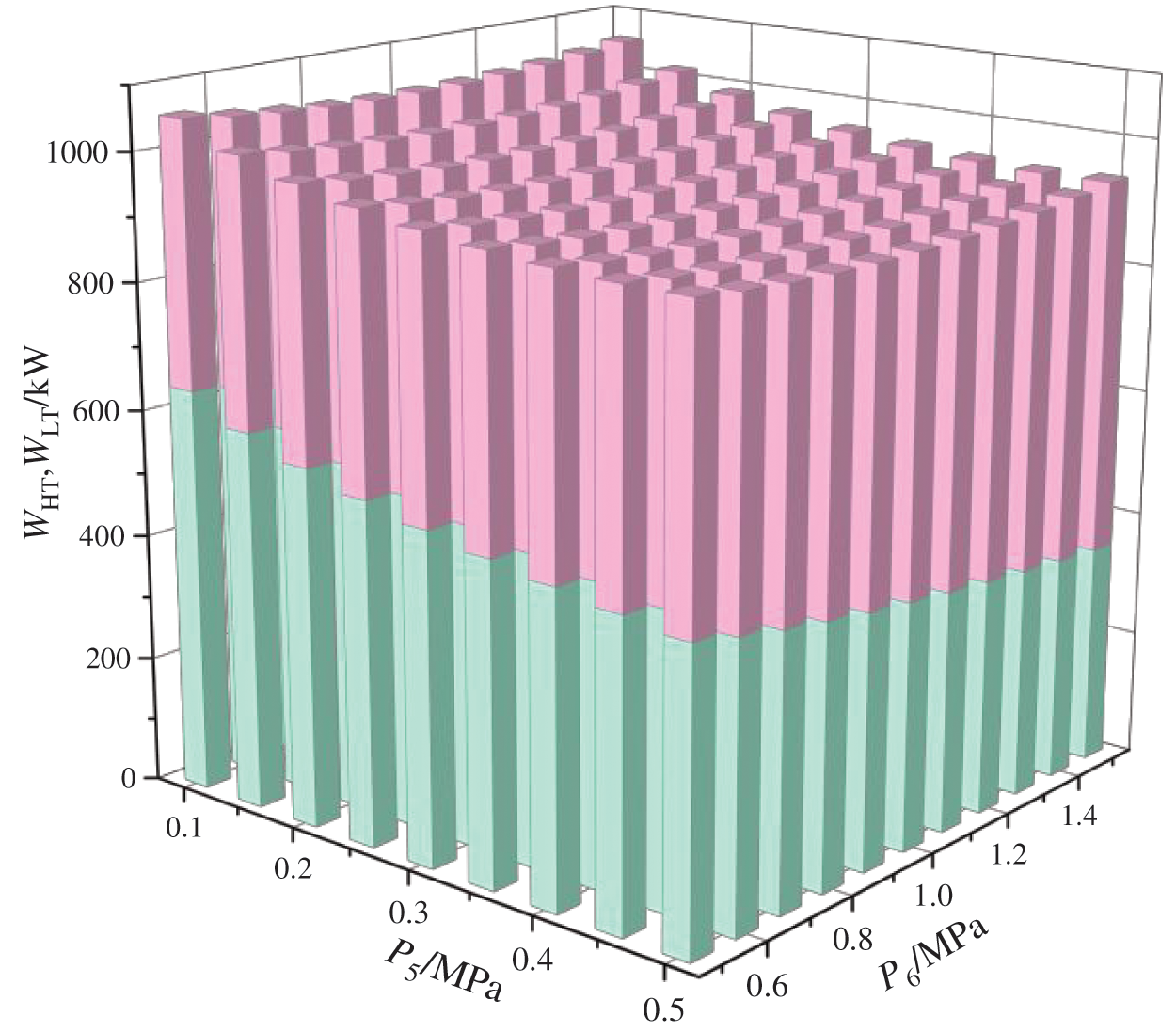
Figure 13: Effects of working fluid pressures of the dual-stage ejector on the output power
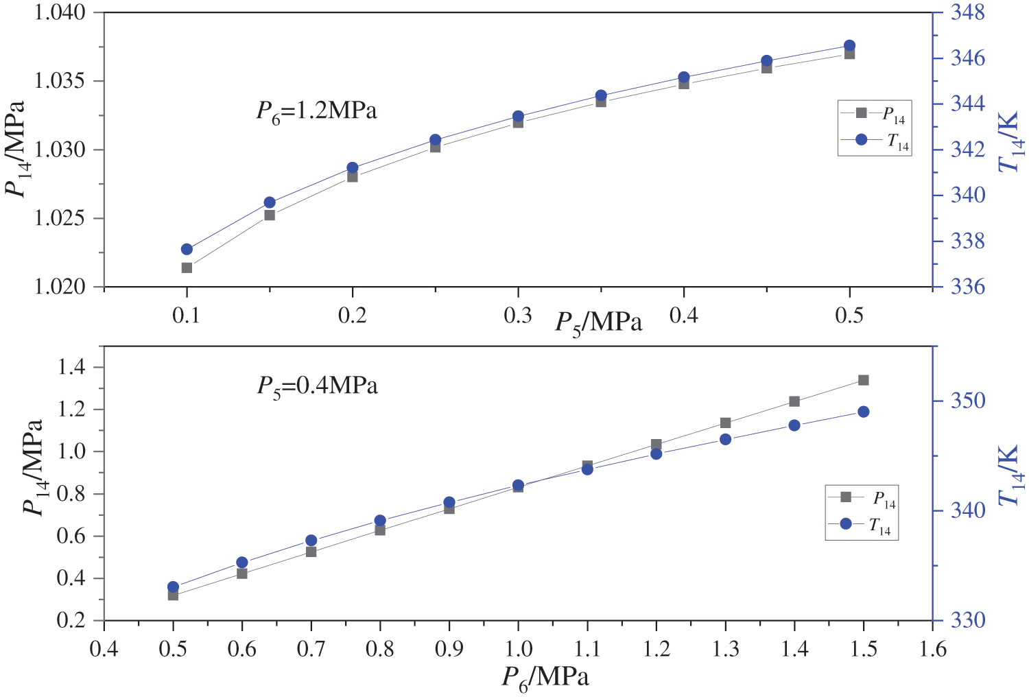
Figure 14: Effects of working fluid pressures of the dual-stage ejector on the outlet temperature and pressure of the dual-stage ejector
Fig. 15 shows the impact of P5 and P6 on ηt and ηex. As P5 and P6 increase, ηt demonstrates an upward trend, while ηex initially decreases before subsequently increasing. For instance, when P6 is set at 1.2 MPa and P5 is raised from 0.1 MPa to 0.5 MPa, there is a corresponding increase in ηt from 18.96% to 19.25%, with ηex decreasing from 43.45% to 38.51% before rebounding to 38.67%. Similarly, when P5 is maintained at 0.4 MPa and P6 is increased from 0.5 MPa to 1.5 MPa, there is a notable rise in ηt from 16.16% to 21.08%, accompanied by a decrease in ηex from 39.49% to 38.46% before ultimately reaching 39.48%. Due to these conditions, the heat absorption of the evaporator remains constant, causing the overall heat absorption trend of the DE-DPORC system to rely on the heat transfer of the regenerator. The increase in T14 leads to a decrease in heat transfer of the regenerator, resulting in reduced total heat absorption and subsequently impacting ηt. As for ηex, with fixed input exergy from the heat source, its variation trend is solely dependent on Wnet and thus follows the same trend as Wnet.
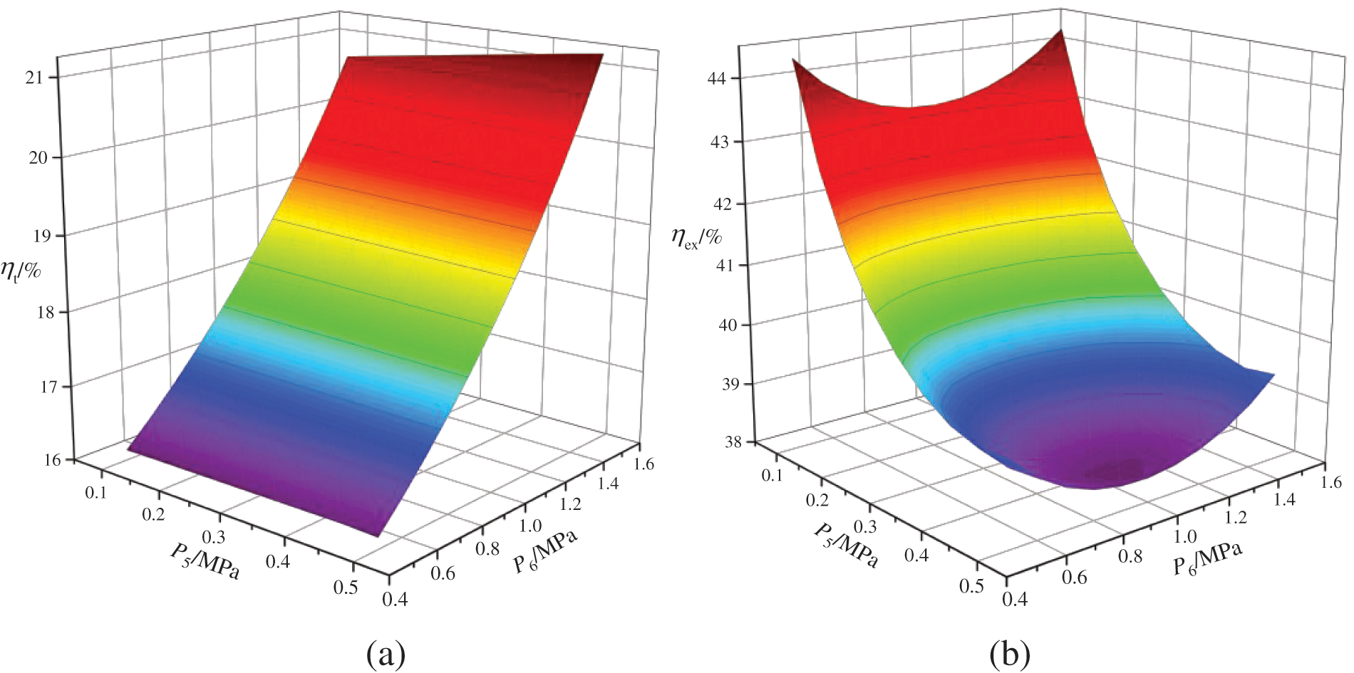
Figure 15: Effects of working fluid pressures of the dual-stage ejector on the thermal efficiency and exergy efficiency (a) shows the effects of working fluid pressures of the dual-stage ejector on the thermal efficiency, and (b) shows the effects of working fluid pressures of the dual-stage ejector on the exergy efficiency
Fig. 16 depicts the impact of P5 and P6 on LEC and AER. As P5 and P6 increase, there is a corresponding increase in LEC and a decrease in AER. Based on the aforementioned analysis, it is evident that an increase in P5 and P6 leads to a decrease in WHT and an increase in WLT, resulting in reduced investment cost and mass of high-pressure expander, as well as increased investment cost and mass of low-pressure expander. Furthermore, the reduction in heat transfer results in decreased investment cost and mass of the regenerator, while slightly increasing the investment cost and mass of the condenser. The investment cost and mass of the evaporator and working fluid pump remain constant. The total investment cost (Ctotal) and the total mass of the equipment are primarily influenced by the high- and low-pressure expander, exhibiting a trend of initial decrease followed by an increase. LEC was initially impacted by the reduction in Wnet, followed by an increase in Ctotal, leading to its continuous growth. Similarly, AER was first affected by a decline in Wnet and subsequently by an increase in Ctotal, resulting in a sustained decrease in its value.
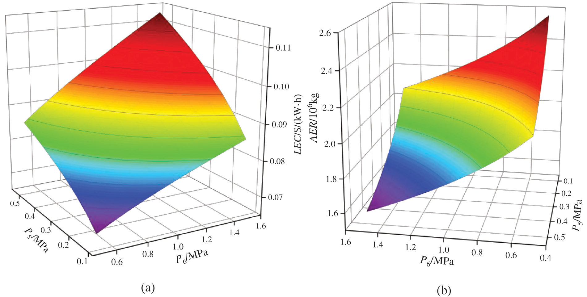
Figure 16: Effects of working fluid pressures of the dual-stage ejector on the levelized energy cost and equivalent CO2 emission reduction (a) shows the effects of working fluid pressures of the dual-stage ejector on the levelized energy cost, and (b) shows the effects of working fluid pressures of the dual-stage ejector on the equivalent CO2 emission reduction
The above analysis reveals that the increase in P5 and P6 primarily results in a decrease in pressure difference at the inlet and outlet of the high-pressure expander, as well as an increase in state parameters at the inlet of the low-pressure expander (the outlet of the dual-stage injector), consequently causing a decrease followed by an increase in Wnet and ηex, an increase in ηt and LEC, and a decrease in AER. It is observed that ηt is more sensitive to changes in P6, while other performance indexes are more sensitive to variations in P5. Under these circumstances, it is challenging for the system to achieve optimal performance simultaneously. In practical applications, setting P5 to 0.1 MPa and P6 to 1.5 MPa yields the highest Wnet and ηex for the DE-DPORC system; setting P5 to 0.5 MPa and P6 to 1.5 MPa maximizes ηt; setting P5 to 0.1 MPa and P6 to 0.5 MPa optimizes LEC and AER. Adjusting operating parameters according to actual demand allows for selecting optimum performance.
5.5 Multi-Objective Optimization Results Analysis
Fig. 17 depicts the Pareto frontiers obtained from the multi-objective optimization of the DE-DPORC system. It is evident that the optimal Wnet falls within the range of 99.74 to 1211.28 kW, while the optimal LEC ranges from 0.057 to 0.14 $/(kW·h), and the optimal AER ranges from 0.63 × 10⁶ kg to 4.65 × 10⁶ kg. Furthermore, there exists a positive proportional relationship among these three objective functions. The TOPSIS method is employed to select a unique optimal solution from numerous Pareto frontiers. Firstly, the positive ideal solution is determined as Wnet = 1211.28 kW, AER = 4.65 × 10⁶ kg, LEC = 0.057 $/(kW·h) based on the Pareto frontiers; the negative ideal solution is determined as Wnet = 99.74 kW, AER = 0.63 × 10⁶ kg, LEC = 0.14 $/(kW·h). Subsequently, the Pareto solution set is normalized and the relative proximity of each point in the set to the optimal solution is calculated by determining their distance from the positive and negative ideal solutions. The ultimately selected optimal solution is Wnet = 1129.37 kW, AER = 4.29 × 10⁶ kg, LEC = 0.13 $/(kW·h) with corresponding optimal working condition TS,in = 426.74 K, T2 = 389.37 K, Er1 = 1.33, Er2 = 3.17, P5 = 0.39 MPa, P6 = 1.32 MPa, as shown in Table 10.
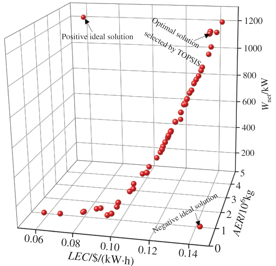
Figure 17: Pareto frontiers and optimal solution of the DE-DPORC system

The determined optimum operating parameters can serve as technical support for the DE-DPORC system in engineering applications, falling within the conventional range and offering ease of operation. Furthermore, these parameters can provide theoretical guidance for DE-DPORC systems of varying scales. However, while the optimized comprehensive performance aligns closely with the optimal value of thermodynamic and environmental performance, it remains distant from achieving the optimal value of economic performance. As a result, the system is unable to simultaneously achieve optimal values across thermodynamic, economic, and environmental performance.
This paper proposed a novel dual-pressure ORC system with a dual-stage ejector (DE-DPORC) aimed at addressing the condensing pressure limitation and maximizing the utilization of steam waste heat. Thermodynamic, economic, and environmental models were developed and compared with a DPORC system under fixed operating conditions. The impacts of steam heat source temperature, evaporation temperature, entrainment ratio, and working fluid pressure on the performance of the DE-DPORC system were analyzed, and multi-objective optimization was conducted to unveil the optimal operational parameters and performance of the system. The main results of the study can be summarized as follows:
(1) In comparison with the DPORC system, the DE-DPORC system demonstrates an increase of 15.26% in output power of the high-pressure expander as outlet pressure decreases, despite a portion of the working fluid being extracted from the high-pressure expander for use in the dual-stage injector. The DE-DPORC system of only one working fluid pump results in a reduction of 43.22% in power consumption, while its single condensation process leads to a decrease of 47.67% in condensation heat loss. These parameters contribute to a 5.34% increase in net power output, a 58.06% improvement in thermal efficiency, a 5.34% enhancement in exergy efficiency, as well as annual equivalent CO2 emission reduction by 5.61%, and a 13.51% decrease in levelized energy cost.
(2) When the steam heat source temperature is fixed, the net output power, thermal efficiency, exergy efficiency, and annual equivalent CO2 emission reduction of the DE-DPORC system exhibit an initial increase followed by a decrease with rising evaporation temperature. However, it should be noted that the maximum points corresponding to different heat source temperatures vary, and there is a reduction in levelized energy cost. Conversely, when the evaporation temperature remains fixed, all aforementioned parameters including net output power, thermal efficiency, exergy efficiency, annual equivalent CO2 emission reduction, and levelized energy cost demonstrate an increase with escalating steam heat source temperature.
(3) The entrainment ratios of the dual-stage ejector are adjusted by the extraction ratios of the high-pressure expander. When the low-pressure extraction ratio is fixed, the two entrainment ratios decrease as the high-pressure extraction ratio increases. However, when the high-pressure extraction ratio remains fixed, the first-stage entrainment ratio decreases while the second-stage entrainment ratio increases with an increase in low-pressure extraction ratio; under these operating conditions, net output power, exergy efficiency, and annual equivalent CO2 emission reduction initially increase and then decrease, while thermal efficiency and levelized energy cost increase.
(4) As the high- and low-pressure working fluid pressures of the dual-stage injector increase, the net output power and exergy efficiency of the DE-DPORC system decrease first and then increase, thermal efficiency and levelized energy cost increase, while the annual equivalent CO2 emission reduction decreases.
(5) The DE-DPORC system exhibits greater sensitivity to internal operating parameters–evaporation temperature, entrainment ratio of the dual-stage ejector, and working fluid pressure of the dual-stage ejector, as these directly impact the operational state parameters of high and low-pressure expanders. Among these factors, the entrainment ratio of the dual-stage ejector is identified as the most influential. Conversely, the system demonstrates lower sensitivity to external parameters - heat source temperature, primarily due to its effect on the mass flow rate of the working fluid.
(6) The optimal operating parameters of the DE-DPORC system are as follows: the steam heat source temperature is 426.74 K, the evaporation temperature is 389.37 K, the first-stage entrainment ratio is 1.33, the second-stage entrainment ratio is 3.17, the low-pressure working fluid pressure is 0.39 MPa, and the high-pressure working fluid pressure is 1.32 MPa. The corresponding optimal performance includes a net output power of 1129.37 kW, an annual equivalent CO2 emission reduction of 4.29 × 10⁶ kg, and a levelized energy cost of 0.13 $/(kW·h). The optimal operating parameter values fall within the conventional range, facilitating practical operation. However, the optimized comprehensive performance is closer to the thermodynamic and environmental optimal values but far from the economic optimum.
(7) The DE-DPORC system has been enhanced based on the existing DPORC system and holds significant practical significance. The utilization of cost-effective, mass-produced components while upholding high reliability and efficiency will contribute to the development of a product that is appealing to the global market. Although the system was initially designed for steam waste heat, it remains suitable for heat sources with relatively high calorific value and temperature. However, the performance and state parameters of different heat source systems will vary, necessitating further exploration.
Acknowledgement: Thank you for the tacit cooperation of the members of the research team, thank you for the strong support of the Liaoning Provincial Key Laboratory of Energy Storage and Utilization, and thank you for the hard work of the editors and reviewers.
Funding Statement: This work was supported by the Foundation of Liaoning Provincial Key Laboratory of Energy Storage and Utilization (Grant Nos. CNWK202304 and CNNK202315), and the Introduction of Talent Research Start-Up Funding Projects of Yingkou Institute of Technology (Grant No. YJRC202107).
Author Contributions: Guowei Li: Conceptualization, Methodology, Software, Investigation, Formal Analysis, Writing—Original Draft, Funding Acquisition. Shujuan Bu: Methodology, Investigation, Data Curation, Writing—Original Draft. Xinle Yang and Kaijie Liang: Visualization, Investigation, Software, Validation, Project Administration. Zhengri Shao and Xiaobei Song: Resources, Supervision. Yitian Tang and Dejing Zong: Visualization, Data Curation, Checking. All authors reviewed the results and approved the final version of the manuscript.
Availability of Data and Materials: Data available on request from the authors.
Ethics Approval: Not applicable.
Conflicts of Interest: The authors declare that they have no conflicts of interest to report regarding the present study.
References
1. G. Kosmadakis, “Industrial waste heat potential and heat exploitation solutions,” Appl. Therm. Eng., vol. 246, Jun. 2024, Art. no. 122957. doi: 10.1016/j.applthermaleng.2024.122957. [Google Scholar] [CrossRef]
2. W. Wu et al., “Enhancing the waste heat utilization of industrial park: A heat pump-centric network integration approach for multiple heat sources and users,” Energy Convers. Manag., vol. 306, Apr. 2024, Art. no. 118306. doi: 10.1016/j.enconman.2024.118306. [Google Scholar] [CrossRef]
3. S. Du, Z. Xu, R. Wang, and C. Yang, “Development of direct seawater-cooled LiBr-H2O absorption chiller and its application in industrial waste heat utilization,” Energy, vol. 294, May 2024, Art. no. 130816. doi: 10.1016/j.energy.2024.130816. [Google Scholar] [CrossRef]
4. M. Valant, U Luin, “Chemistry of the iron-chlorine thermochemical cycle for hydrogen production utilizing industrial waste heat,” J. Clean. Prod., vol. 438, Jan. 2024, Art. no. 140681. doi: 10.1016/j.jclepro.2024.140681. [Google Scholar] [CrossRef]
5. A. Liang, S. Yang, Y. Ding, and S. Ma, “Triple effect absorption refrigeration systems for the deep recovery of low grade waste heat,” Appl. Therm. Eng., vol. 250, Aug. 2024, Art. no. 123500. doi: 10.1016/j.applthermaleng.2024.123500. [Google Scholar] [CrossRef]
6. M. Zhang, L. Shi, P. Hu, G. Pei, and G. Shu, “Carnot battery system integrated with low-grade waste heat recovery: Toward high energy storage efficiency,” J. Energy Storage, vol. 57, Jan. 2023, Art. no. 106234. doi: 10.1016/j.est.2022.106234. [Google Scholar] [CrossRef]
7. Y. Li, W. Wang, Y. F. Ma, and W. Li, “Study of new cascade heating system with multi-heat sources based on exhausted steam waste heat utilization in power plant,” Appl. Therm. Eng., vol. 136, pp. 475–483, May 2018. doi: 10.1016/j.applthermaleng.2018.01.033. [Google Scholar] [CrossRef]
8. S. Zhao, Z. Ge, J. He, C. Wang, Y. Yang and P. Li, “A novel mechanism for exhaust steam waste heat recovery in combined heat and power unit,” Appl. Energy, vol. 204, pp. 596–606, Oct. 2017. doi: 10.1016/j.apenergy.2017.07.068. [Google Scholar] [CrossRef]
9. D. Ji, H. Cai, Z. Ye, D. Luo, G. Wu and A. Romagnoli, “Comparison between thermoelectric generator and organic Rankine cycle for low to medium temperature heat source: A Techno-economic analysis,” Sustain. Energy Technol. Assess., vol. 55, Feb. 2023, Art. no. 102914. doi: 10.1016/j.seta.2022.102914. [Google Scholar] [CrossRef]
10. R. Pili, L. García Martínez, C. Wieland, and H. Spliethoff, “Techno-economic potential of waste heat recovery from German energy-intensive industry with Organic Rankine Cycle technology,” Renew. Sustain. Energy Rev., vol. 134, Dec. 2020, Art. no. 110324. doi: 10.1016/j.rser.2020.110324. [Google Scholar] [CrossRef]
11. S. Lin, L. Zhao, S. Deng, J. Ni, Y. Zhang and M. Ma, “Dynamic performance investigation for two types of ORC system driven by waste heat of automotive internal combustion engine,” Energy, vol. 169, pp. 958–971, Feb. 2019. doi: 10.1016/j.energy.2018.12.092. [Google Scholar] [CrossRef]
12. R. de Oliveira Neto, C. A. R. Sotomonte, and C. J. R. Coronado, “Off-design model of an ORC system for waste heat recovery of an internal combustion engine,” Appl. Therm. Eng., vol. 195, Aug. 2021, Art. no. 117188. doi: 10.1016/j.applthermaleng.2021.117188. [Google Scholar] [CrossRef]
13. B. -R. Fu, J. -C. Hsieh, S. -M. Cheng, and M. A. Royandi, “Thermoeconomic analysis of a novel cogeneration system for cascade recovery of waste heat from exhaust flue gases,” Appl. Therm. Eng., vol. 247, Jun. 2024, Art. no. 123034. doi: 10.1016/j.applthermaleng.2024.123034. [Google Scholar] [CrossRef]
14. Z. Wang, H. Chen, R. Xia, F. Han, Y. Ji and W. Cai, “Energy, exergy and economy (3E) investigation of a SOFC-GT-ORC waste heat recovery system for green power ships,” Therm. Sci. Eng. Prog., vol. 32, Jul. 2022, Art. no. 101342. doi: 10.1016/j.tsep.2022.101342. [Google Scholar] [CrossRef]
15. Z. Zheng, J. Cao, W. Wu, and M. K. H. Leung, “Parallel and in-series arrangements of zeotropic dual-pressure Organic Rankine Cycle (ORC) for low-grade waste heat recovery,” Energy Rep., vol. 8, pp. 2630–2645, Nov. 2022. doi: 10.1016/j.egyr.2022.01.057. [Google Scholar] [CrossRef]
16. H. Wang, R. Peterson, and T. Herron, “Design study of configurations on system COP for a combined ORC (organic Rankine cycle) and VCC (vapor compression cycle),” Energy, vol. 36, no. 8, pp. 4809–4820, Aug. 2011. doi: 10.1016/j.energy.2011.05.015. [Google Scholar] [CrossRef]
17. J. Li, Z. Ge, Y. Duan, Z. Yang, and Q. Liu, “Parametric optimization and thermodynamic performance comparison of single-pressure and dual-pressure evaporation organic Rankine cycles,” Appl. Energy, vol. 217, no. 2, pp. 409–421, May 2018. doi: 10.1016/j.apenergy.2018.02.096. [Google Scholar] [CrossRef]
18. Y.-Q. Feng et al., “Parametric analysis and thermal-economical optim-ization of a parallel dual pressure evaporation and two stage regenerative organic Rankine cycle using mixture working fluids,” Energy, vol. 263, Feb. 2023, Art. no. 125670. doi: 10.1016/j.energy.2022.125670. [Google Scholar] [CrossRef]
19. T. Li, J. Zhu, K. Hu, Z. Kang, and W. Zhang, “Implementation of PDORC (parallel double-evaporator organic Rankine cycle) to enhance power output in oil field,” Energy, vol. 68, no. 3, pp. 680–687, Apr. 2014. doi: 10.1016/j.energy.2014.03.007. [Google Scholar] [CrossRef]
20. Q. Sun, Y. Wang, Z. Cheng, J. Wang, P. Zhao and Y. Dai, “Thermodynamic and economic optimization of a double-pressure organic Rankine cycle driven by low-temperature heat source,” Renew. Energy, vol. 147, no. 5, pp. 2822–2832, Mar. 2020. doi: 10.1016/j.renene.2018.11.093. [Google Scholar] [CrossRef]
21. Y. Chen, Y. Liu, E. -Y. Nam, Y. Zhang, and A. Dahlak, “Exergoeconomic and exergoenvironmental analysis and optimization of an integrated double-flash-binary geothermal system and dual-pressure ORC using zeotropic mixtures; multi-objective optimization,” Energy, vol. 283, Nov. 2023, Art. no. 128367. doi: 10.1016/j.energy.2023.128367. [Google Scholar] [CrossRef]
22. L. Afif, A. Elamari, and N. Bouaziz, “Energetic study and comparative analysis of two novel ORC cogeneration systems using gas ejectors,” Energy Proc., vol. 157 pp. 1220–1229, Jan. 2019. doi: 10.1016/j.egypro.2018.11.288. [Google Scholar] [CrossRef]
23. J. Wu, Y. Liang, Z. Sun, Y. Zhu, J. Ye and J. Lu, “Dynamic analysis and control strategy of ORC coupled ejector expansion refrigeration cycle driven by geothermal water,” J. Clean. Prod., vol. 445, Mar. 2024, Art. no. 141309. doi: 10.1016/j.jclepro.2024.141309. [Google Scholar] [CrossRef]
24. H. Mortazavi, H. M. Beni, A. A. Nadooshan, M. S. Islam, and M. Ghalambaz, “4E analysis and triple objective NSGA-II optimization of a novel solar-driven combined ejector-enhanced power and two-stage cooling (EORC-TCRC) system,” Energy, vol. 294, May 2024, Art. no. 130803. doi: 10.1016/j.energy.2024.130803. [Google Scholar] [CrossRef]
25. P. Haghparast, M. V. Sorin, M. A. Richard, and H. Nesreddine, “Analysis and design optimization of an ejector integrated into an organic Rankine cycle,” Appl. Therm. Eng., vol. 159, Aug. 2019, Art. no. 113979. doi: 10.1016/j.applthermaleng.2019.113979. [Google Scholar] [CrossRef]
26. M. Srivastava, J. Sarkar, A. Sarkar, N. K. Maheshwari, and A. Antony, “4E analysis and optimization of novel ejector-enhanced organic Rankine cycles by introducing new economic models,” Therm. Sci. Eng. Prog., vol. 41, Jun. 2023, Art. no. 101855. doi: 10.1016/j.tsep.2023.101855. [Google Scholar] [CrossRef]
27. L. Mohammadi Hadelu and F. Ahmadi Boyaghchi, “Exergoeconomic and exergoenvironmental analyses and optimization of different ejector based two stage expander-organic flash cycles fuelled by solar energy,” Energy Convers. Manag., vol. 216, Jul. 2020, Art. no. 112943. doi: 10.1016/j.enconman.2020.112943. [Google Scholar] [CrossRef]
28. Y. Yao and P. Hrnjak, “The effect of fluid properties on development of two-phase flow after an expansion valve based on the comparison of R245fa and R134a,” Int. J. Refrig., vol. 158, pp. 353–364, Feb. 2024. doi: 10.1016/j.ijrefrig.2023.12.010. [Google Scholar] [CrossRef]
29. S. Cao, G. Wang, X. Wu, W. Yang, and C. Hu, “An experimental investigation of R245fa flow boiling heat transfer performance in horizontal and vertical tubes,” Int. J. Refrig., vol. 160, pp. 229–245, Apr. 2024. doi: 10.1016/j.ijrefrig.2024.02.008. [Google Scholar] [CrossRef]
30. S. Bu, X. Yang, W. Li, C. Su, W. Dai and X. Wang, “Comprehensive performance analysis and optimization of novel SCR-ORC system for condensation heat recovery,” Appl. Therm. Eng., vol. 201, Jan. 2022, Art. no. 117825. doi: 10.1016/j.applthermaleng.2021.117825. [Google Scholar] [CrossRef]
31. G. Shu, L. Liu, H. Tian, H. Wei, and G. Yu, “Parametric and working fluid analysis of a dual-loop organic Rankine cycle (DORC) used in engine waste heat recovery,” Appl. Energy, vol. 113, pp. 1188–1198, Jan. 2014. doi: 10.1016/j.apenergy.2013.08.027. [Google Scholar] [CrossRef]
32. Y. Feng, Y. Zhang, B. Li, J. Yang, and Y. Shi, “Comparison between regenerative organic Rankine cycle (RORC) and basic organic Rankine cycle (BORC) based on thermoeconomic multi-objective optimization considering exergy efficiency and levelized energy cost (LEC),” Energ Convers. Manage., vol. 96, pp. 58–71, May 2015. doi: 10.1016/j.enconman.2015.02.045. [Google Scholar] [CrossRef]
33. “Chemical engineering, economic Indicators,” Accessed: May 18, 2024. [Online]. Available: https://www.chemengonline.com/site/plant-cost-index/ [Google Scholar]
34. T. Li, N. Meng, J. Liu, J. Zhu, and X. Kong, “Thermodynamic and economic evaluation of the organic Rankine cycle (ORC) and two-stage series organic Rankine cycle (TSORC) for flue gas heat recovery,” Energ Convers. Manage., vol. 183, no. 6, pp. 816–829, Mar. 2019. doi: 10.1016/j.enconman.2018.12.094. [Google Scholar] [CrossRef]
35. S. Bu, X. Yang, W. Li, W. Dai, C. Su and X. Wang, “Energy, exergy, environmental, and economic analyses and multiobjective optimization of a DSORC system for waste heat utilization in low-concentration gas power generation,” Energy, vol. 286, no. 3, Jan. 2024, Art. no. 129647. doi: 10.1016/j.energy.2023.129647. [Google Scholar] [CrossRef]
36. S. M. Alirahmi, A. Behzadi, P. Ahmadi, and S. Sadrizadeh, “An innovative four-objective dragonfly-inspired optimization algorithm for an efficient, green, and cost-effective waste heat recovery from SOFC,” Energy, vol. 263, Jan. 2023, Art. no. 125607. doi: 10.1016/j.energy.2022.125607. [Google Scholar] [CrossRef]
37. N. Mahdavi, P. Mojaver, and S. Khalilarya, “Multi-objective optimization of power, CO2 emission and exergy efficiency of a novel solar-assisted CCHP system using RSM and TOPSIS coupled method,” Renew. Energy, vol. 185, pp. 506–524, Feb. 2022. doi: 10.1016/j.renene.2021.12.078. [Google Scholar] [CrossRef]
38. N. B. Sag, H. K. Ersoy, A. Hepbasli, and H. S. Halkaci, “Energetic and exergetic comparison of basic and ejector expander refrigeration systems operating under the same external conditions and cooling capacities,” Energy Convers. Manag., vol. 90, pp. 184–194, Jan. 2015. doi: 10.1016/j.enconman.2014.11.023. [Google Scholar] [CrossRef]
39. T. Sung and K. C. Kim, “An organic Rankine cycle for two different heat sources: Steam and hot water,” Energy Proc., vol. 129, pp. 883–890, Sep. 2017. doi: 10.1016/j.egypro.2017.09.251. [Google Scholar] [CrossRef]
Cite This Article
 Copyright © 2024 The Author(s). Published by Tech Science Press.
This work is licensed under a Creative Commons Attribution 4.0 International License , which permits unrestricted use, distribution, and reproduction in any medium, provided the original work is properly cited.


 Submit a Paper
 Propose a Special lssue
 View Full Text
 Download PDF

 Downloads
 Citation Tools