 Open Access
ARTICLE
Heuristic-Based Optimal Load Frequency Control with Offsite Backup Controllers in Interconnected Microgrids
School of Mechatronic Engineering and Automation, Shanghai University, Shanghai, 200444, China
* Corresponding Author: Tingzhang Liu. Email:
Energy Engineering 2024, 121(12), 3735-3759. https://doi.org/10.32604/ee.2024.054687
Received 05 June 2024; Accepted 18 August 2024; Issue published 22 November 2024
Abstract
The primary factor contributing to frequency instability in microgrids is the inherent intermittency of renewable energy sources. This paper introduces novel dual-backup controllers utilizing advanced fractional order proportional integral derivative (FOPID) controllers to enhance frequency and tie-line power stability in microgrids amid increasing renewable energy integration. To improve load frequency control, the proposed controllers are applied to a two-area interconnected microgrid system incorporating diverse energy sources, such as wind turbines, photovoltaic cells, diesel generators, and various storage technologies. A novel meta-heuristic algorithm is adopted to select the optimal parameters of the proposed controllers. The efficacy of the advanced FOPID controllers is demonstrated through comparative analyses against traditional proportional integral derivative (PID) and FOPID controllers, showcasing superior performance in managing system fluctuations. The optimization algorithm is also evaluated against other artificial intelligent methods for parameter optimization, affirming the proposed solution’s efficiency. The robustness of the intelligent controllers against system uncertainties is further validated under extensive power disturbances, proving their capability to maintain grid stability. The dual-controller configuration ensures redundancy, allowing them to operate as mutual backups, enhancing system reliability. This research underlines the importance of sophisticated control strategies for future-proofing microgrid operations against the backdrop of evolving energy landscapes.Keywords
The integration of intermittent renewable energy and the proliferation of electric vehicles (EV) has reduced system inertia, intensifying the challenges associated with grid stability, particularly in frequency and tie-line power flow management [1]. Historical approaches to this dilemma have seen the development of various strategies within multi-area interconnected power systems aimed at fortifying frequency stability [2], including the utilization of tilt-integral-derivative (TID) controller [3,4], integration of controller gain optimization and anti-windup augmentation [5], the deployment of robust
Among these, fractional order PID (FOPID) controllers also have distinguished themselves, recognized for their robust performance, reduced steady-state error, and formidable disturbance rejection capabilities, particularly in load frequency control (LFC) scenarios [14]. The effectiveness of FOPID controllers is dependent on the fine-tuning of the λ and μ parameters in conjunction with the conventional proportional (kP), integral (kI), and derivative (kD) coefficients [14]. A Cascaded FOPID-tilt integrator differentiator with filter (TIDF) based on Manta-Ray Foraging Optimization is proposed in [15]. Besides, a cascaded proportional integral-tilt integral derivative (PI-TID) controller with parameters optimized utilizing chaotic butterfly optimization (CBO) was proposed in [16]. Reference [17] combined TID controller and Harris hawks optimization optimization (HHO) to obtain better performance than PID and PI controllers. Despite their advantages, the fine-tuning of these parameters remains challenging due to microgrids’ intrinsic non-linearity and uncertainty owing to evolving lifestyle patterns, escalating energy consumption, industrial advancement, ecological considerations, and advancements in power grid infrastructure [18]. Addressing this challenge of optimum parameters, other meta-heuristic optimization techniques, including Kharitonov’s theorem applications [19] and Gases Brownian Motion Optimization (GBMO) [20], have been proposed, albeit at the cost of increased computational complexity.
This research examines a two-area interconnected microgrid system incorporating diverse intermittent renewable resources such as wind turbine generators (WG), solar photovoltaics (PV), diesel generators (DsG), fuel cells (FC), flywheel storage systems (FWSS), and battery energy storage system (BESS). We introduce two innovative structures of FOPID controller designs—FOPID cascaded with fractional-order PI (FOPID-C-FOPI) and parallel fractional-order PI (FOPID-P-FOPI)—to advance the LFC responsiveness and flexibility. These designs exceed the disturbance rejection and robustness of conventional PID [21] and FOPID controllers. The novel controllers are fine-tuned using a Heap-Based Optimization (HBO) algorithm [22], which optimizes the hierarchical decision-making characteristic of corporate structures, enhancing efficiency in problem-solving.
In this structured approach, we explore the foundational concepts of HBO, delineate the system model, articulate the optimization challenges, and discuss controller design and implementation. This optimization method allows the proposed controllers to operate as mutual backups, enhancing system reliability under various oscillations.
The paper progresses with a comprehensive system model in Section 2, an exposition of the optimization challenges and controller strategies in Section 3, and a detailed analysis of simulation outcomes in Section 4. Section 5 concludes the paper with a synopsis of key findings and their implications for future system operation and research.
This study investigates a dual-area Microgrid (MG) network, each encompassing DsG, FC, WG, PV, FWSS, and BESS. Fig. 1 illustrates the control architecture of the interconnected MGs.

Figure 1: Control diagram of the interconnected system
Control signals, ∆u1 and ∆u2, emitted by two structurally identical but parameter-differentiated controllers, are predicated on the area control error (ACE) of each MG, denoted as
System variations encompass wind generation changes (
The subsequent sections provide an academic outline of various renewable and storage systems within an MG. They are structured sequentially concerning their functions, dynamic models, and roles within the broader MG control context.
2.1 Diesel Generator (DsG) Dynamics
DsG units are pivotal in isolated MG systems, offering fast start-up, high efficiency, and long service life. They dynamically balance power supply to mitigate perturbations and renewable source fluctuations, critical for transient response enhancement [23,24]. The DsG model, a first-order representation including governor and turbine dynamics [25], encapsulates power adjustments in response to frequency variations in Eq. (3).
where
Derived from first-order governor and generator models, the dynamic DsG model incorporates ramp rate and power output constraints under saturation conditions. Fig. 2 demonstrates the model input as frequency deviation (

Figure 2: Dynamic model of DsG unit
2.2 Fuel Cell (FC) Unit Dynamics
FC units contribute to power equilibrium by converting chemical to electrical energy using eco-friendly hydrogen and oxygen [26]. The FC dynamics are represented by a third-order transfer function in Eq. (4), capturing the system’s time constants and responsiveness to control signals from LFC.
where

Figure 3: Dynamic model of FC. Adapted from Refenence [27]
2.3 Energy Storage Systems Dynamics
Battery energy storage system (BESS) and flywheel storage system (FWSS) are modeled as first-order systems in Eqs. (5) and (6), which are crucial for PFC by absorbing and dispatching energy in response to frequency deviations. Both are modeled to provide only PFC, with their dynamics solely responsive to local frequency variations (∆F). Exhibited in Fig. 4, their first-order transfer functions, denoted as
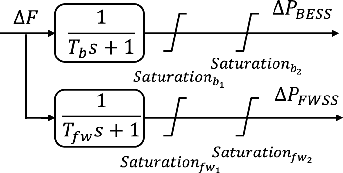
Figure 4: Dynamic model of BESS and FWSS. Reprinted from Reference [28]
These models produce power fluctuations (
PV units, devoid of mechanical inertia, rely on solar irradiance changes to modulate power output. The photovoltaic (PV) system model takes the variation of solar irradiation (∆γ) as its input, which diverges from the traditional second-order models referenced in [29] by incorporating additional dynamics. The resulting PV power output variation (
where

Figure 5: Dynamic model of PV
WG systems, inherently non-dispatchable, are characterized by a first-order transfer function in Eq. (8). The model relies on wind speed variations to predict power output changes, highlighting the WG’s responsive nature to environmental conditions [30].
where

Figure 6: Dynamic model of WG
The optimization framework prioritizes an objective function to minimize frequency fluctuations and concurrent tie-line power imbalances. Within this construct, innovative controller configurations, specifically the FOPID-C-FOPI and FOPID-P-FOPI, are integrated into the LFC loop to formulate control directives for DsG. The calibration of these novel controllers leverages the advanced HBO algorithm to refine their parameters for optimal performance.
LFC aims to mitigate deviations in system frequency and tie-line power. Accordingly, the optimization target is formulated as an integral time-multiplied absolute error (ITAE) metric, quantified in Eq. (9) to evaluate performance deviations over time.
Utilizing the ITAE index, the optimization problem aims to minimize the ITAE value, subject to constraints delineated in Eqs. (10)–(14):
where
To mitigate frequency and tie-line power deviations stemming from renewable energy variability and load disturbances, advanced PID variants such as the Tilt-Integral-Derivative (TID) controller [3] and the Integral-Derivative-Tilted (ID-T) controller [4] were developed. These approaches address the complexities introduced by the proportional gain substitution

Figure 7: FOPID cascaded FOPI
Various methodologies for fractional order derivatives and integrals have been developed, including the Grunwald–Letnikov, Riemann–Liouville (RL), and Caputo definitions, alongside the Carlson and Matsuda approximations [33]. Notably, the Riemann–Liouville definition is frequently employed for fractional derivatives, as specified in Eq. (16) [34]:
where
The Laplace transform is extensively employed to represent both fractional and integer order differentiations. Typically, for a fractional order α where 0 < α < 1, the Laplace transform of the Riemann-Liouville fractional derivative or integral is defined in Eq. (18):
Under zero initial conditions for
where L{·} represents the Laplace transform, indicating that for dynamic systems described by differential equations with fractional derivatives and assumed zero initial conditions, the resultant transfer functions are characterized by fractional-order s.
The transfer function for the proposed FOPID-C-FOPI controller is defined in Eq. (20):
To back up the efficacy of the proposed FOPID-C-FOPI controller, its performance is compared with that of another proposed FOPID-P-FOPI controller, whose transfer function is detailed in Eq. (21) and depicted in Fig. 8, as well as with traditional FOPID and PID controllers.
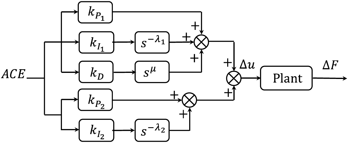
Figure 8: FOPID parallel FOPI
The proposed controllers, acting as mutual backup and employing fractional calculus and a superimposed structure, offer greater flexibility compared to traditional FOPID and PID controllers. Nevertheless, parameter tuning for FOPID presents significant challenges, which can be effectively addressed using the HBO algorithm.
The recently introduced HBO algorithm harnesses a hierarchical rank structure to update population positions based on interactions among various corporate ranks, as detailed in [22]. Fig. 9a illustrates this concept through a corporate rank hierarchy (CRH), where the chief executive officer (CEO) holds the top position as the root node. Reporting directly to the CEO are the chief operating officer (COO) and chief financial officer (CFO), who manage multiple departments. Colleagues in this context are individuals at the same hierarchical level within the organization.

Figure 9: Examples of corporate rank hierarchy and 3-ary min heap
The necessity for meta-heuristics becomes apparent in optimization scenarios involving multiple variables and large search domains, where traditional methods falter due to complexity. The HBO algorithm, a novel meta-heuristic, incorporates the principles of organizational behavior into its strategy. It employs a heap data structure for its non-linear, tree-based organization, typically used in priority queues, to mirror the CRH effectively. Fig. 9b displays a ternary (3-ary) minimum heap, demonstrating how CRH is represented within the algorithm. This structure aids in organizing solutions by their fitness values, thus enabling efficient position updates within the algorithm. HBO uniquely integrates three types of employee interactions: between subordinates and their direct bosses, among peers, and individual efforts toward the optimization process, enhancing the algorithm’s efficacy and applicability to complex problems.
Fig. 10 illustrates the modeling of CRH using a heap data structure, where xi denotes the i-th search agent in the population. The figure shows the objective function’s landscape, with search agents positioned according to their fitness values. Agents are organized into a heap based on their fitness, where each node’s placement reflects its fitness value. For example, x4 is identified as the optimal solution and is positioned at the heap’s root. Notably, min-heaps are utilized for minimization tasks, while max-heaps are appropriate for maximization objectives.

Figure 10: Illustration of the modeling of the CRH with min-heap
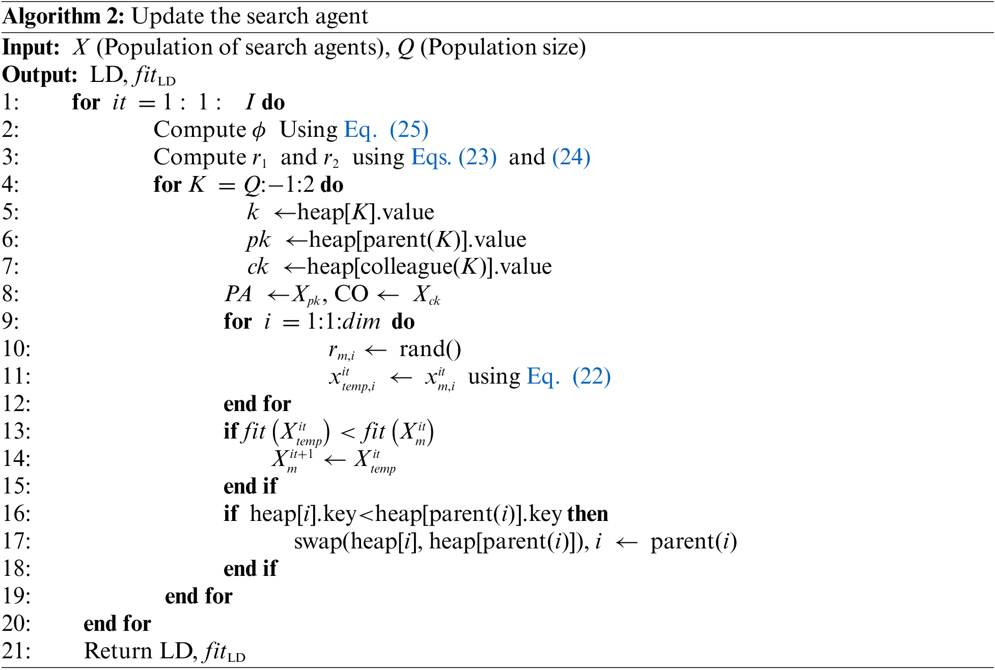
The HBO algorithm leverages a ternary tree structure, or minimum heap, to optimize decision-making by utilizing hierarchical connections among agents, including direct supervisors, peers, and intrinsic motivation. The hierarchy is organized with the leader agent, possessing the highest fitness value, at the top, followed by parent agents on the second tier, and the rest agents on the third. The updated dynamics of this structure are detailed in Eq. (22):
where
where I represents the total number of iterations, with it denoting the current iteration, the probabilities
where mod(x/y) represents a modulus operation, and ψ is computed best as I/25. Throughout the iterative process, ϕ linearly decreases from 2 to 0 and then increases to 2. The parameter ψ is crucial as it determines how many cycles ϕ completes during I iterations. For clarity, two scenarios are illustrated in Fig. 11: in the first, ψ is set to 2, and in the second, to 5, with I consistently at 200. Fig. 11b highlights the potential positions of
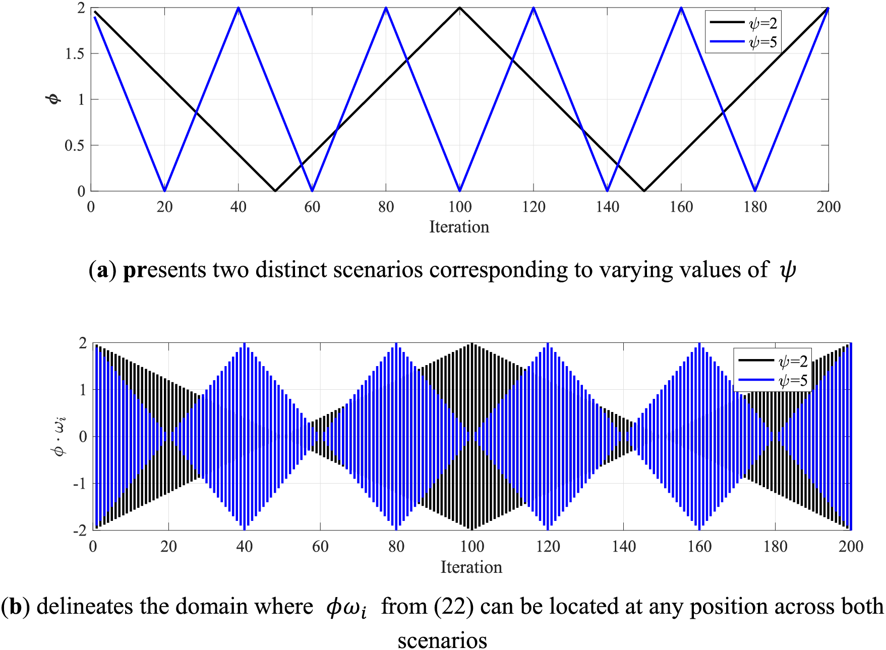
Figure 11: Visualization of the influence of parameters
In Eq. (22), the second term defines
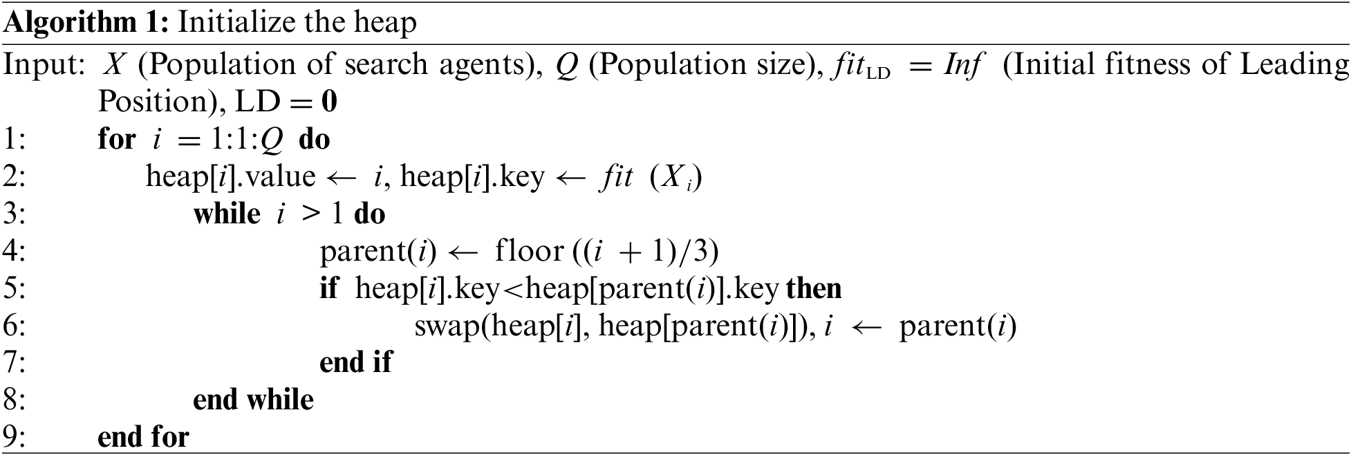
Algorithm 1 illustrates the initialization of the heap structure, and Algorithm 2 details the position updates. Within these algorithms, heap[·].value holds the population index of each agent, while heap[·].key records the agent’s fitness. The pseudocode for initializing and updating agents is provided in Algorithms 1 and 2, respectively.
4 Simulation Results and Discussions
Simulations were conducted using MATLAB to analyze a system consisting of two interconnected AC MGs, with MG 1 experiencing all load and renewable generation fluctuations (see Fig. 1). Detailed system parameters and constraints on ramp rates and power output are listed in the Appendix A [28,29,35].
Fig. 12 illustrates wind speed and solar irradiation variations, with a constant wind speed of 5 m/s superimposed with white noise, resulting in a power spectral density (PSD) of 0.02, depicted by the black line. Wind power variations due to this noise are shown in blue. Additionally, fluctuations in solar irradiation and the corresponding PV power output variation are represented by pink and red lines in Fig. 12.
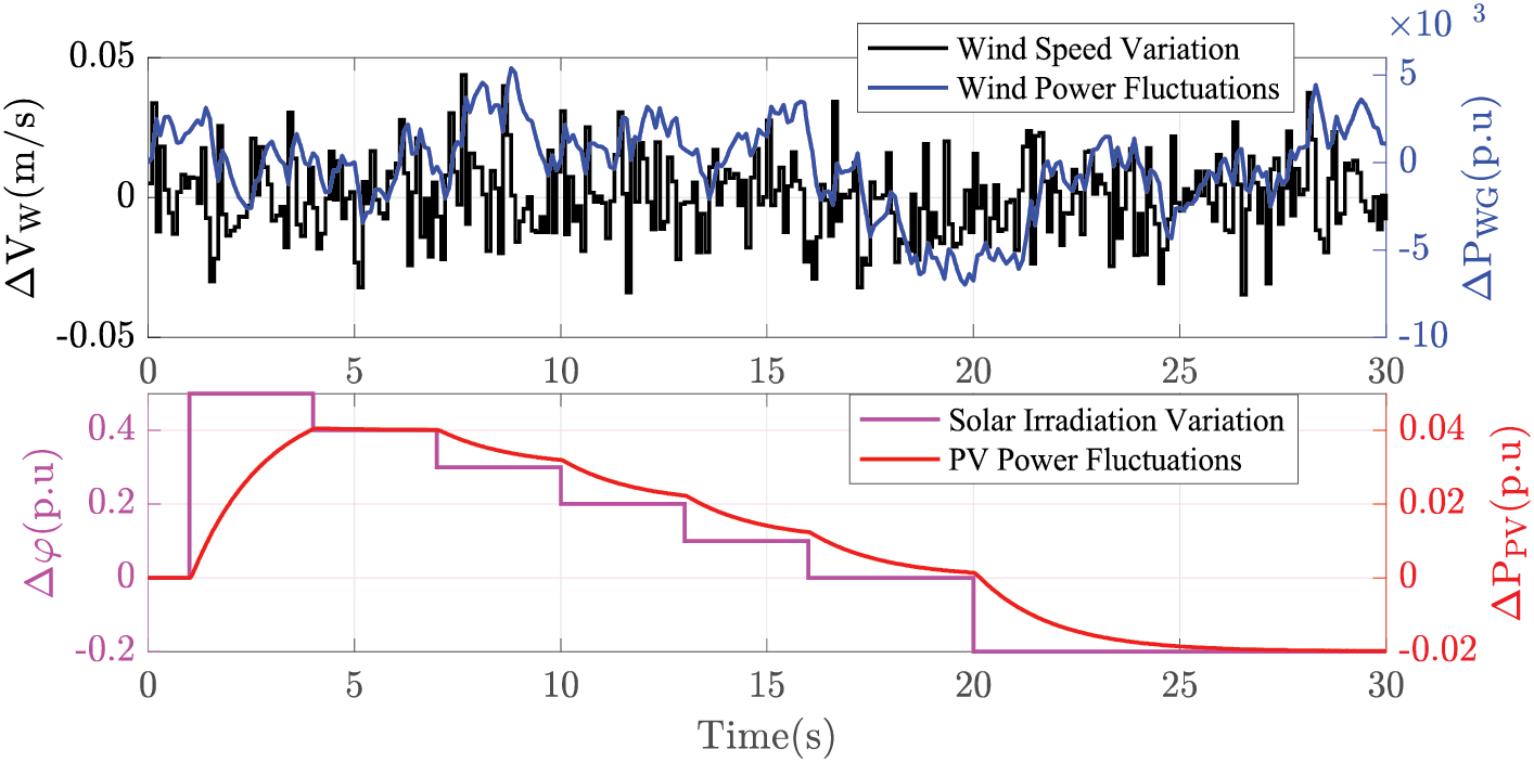
Figure 12: Power changing patterns of WG and PV
4.1 Validation of the Proposed Structures of the Controllers
The efficacy of the FOPID-C-FOPI controller is systematically validated by benchmarking its response against traditional FOPID [14], PID [21], and alternative FOPID-P-FOPI controllers across two distinct scenarios. For this analysis, it is presumed that only load step changes impact the system, with the output from PV and WG held constant (∆γ = 0 and ∆v = 0).
Scenario 1 involves a 0.1 p.u. step increase in load within MG 1 (as depicted in Fig. 1), termed step load augmentation (SLA). For this scenario, the tuning ranges for the proportional (
Parameter optimization for all controllers employs the HBO method, maintaining consistency in population size and iteration limits across evaluations. The dynamic responses for this scenario, alongside the comparative fitness values of the controllers through iterative adjustments, are illustrated in Figs. 13, 14 and Table 1.
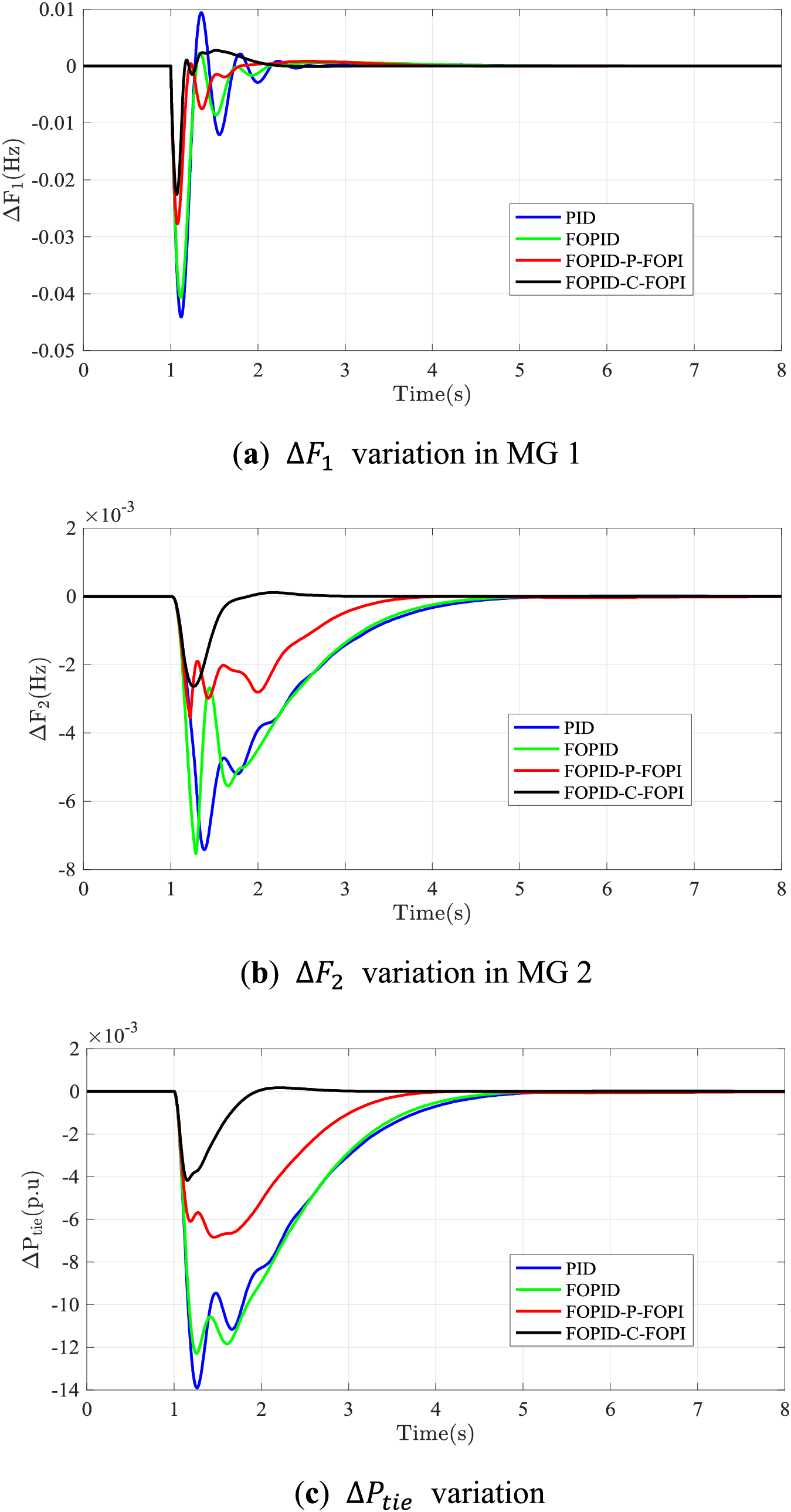
Figure 13: Responses of the interconnected MGs based on SLA under different controllers
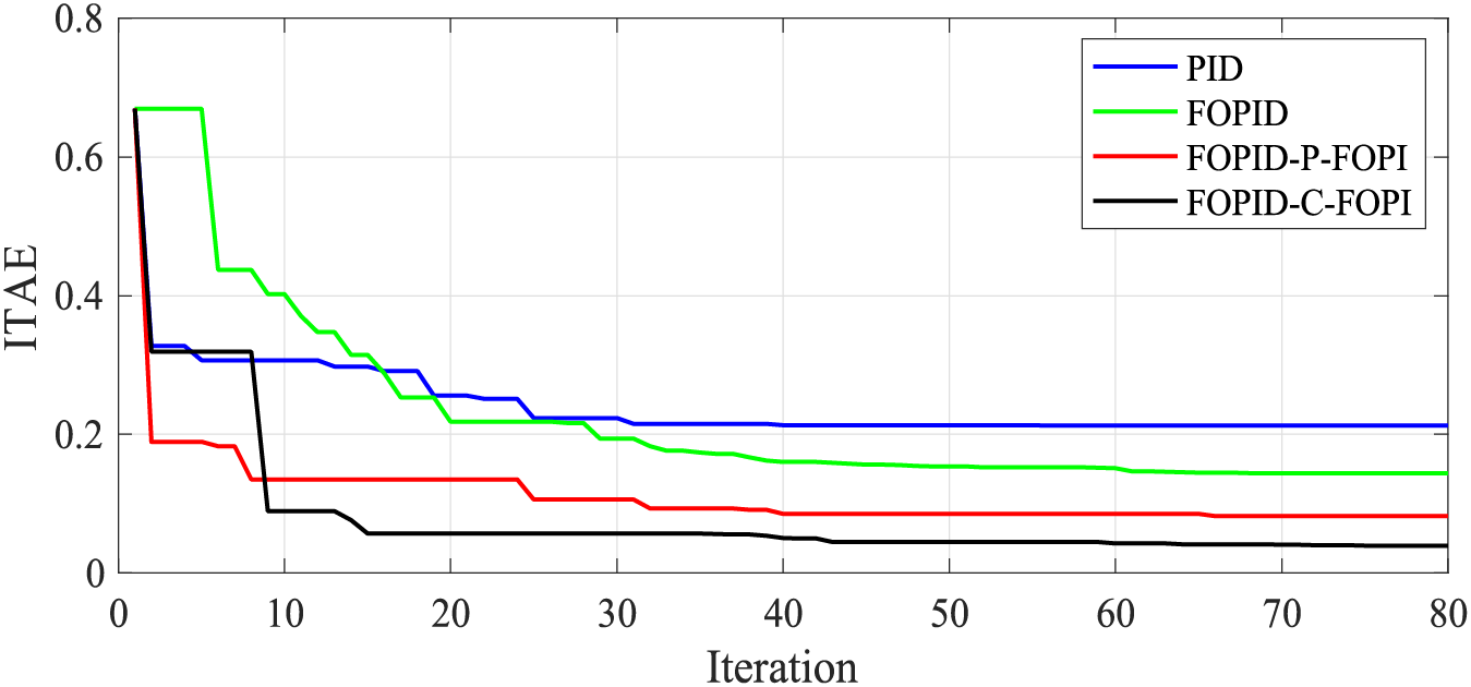
Figure 14: Fitness values of four controllers

In Scenario 1, the FOPID-C-FOPI and FOPID-P-FOPI controllers significantly outperform traditional PID and FOPID controllers in reducing frequency and tie-line power fluctuations across MGs despite all being optimized via the same HBO algorithm. The FOPID-C-FOPI controller reduces F1 reduction by up to 48.8% compared to PID, demonstrating superior control efficacy, while the FOPID-P-FOPI controller performs the lowest ∆F1 overshoot. This performance superiority extends to ∆F2 and tie-line power variance, with FOPID-C-FOPI showing flatter and faster convergence profiles.
When optimized using the HBO algorithm, the FOPID-C-FOPI and FOPID-P-FOPI controllers demonstrate leading and second performance compared to the PID, FOPID, and FOPID-P-FOPI controllers, as evidenced in Fig. 14. Despite having 16 parameters to tune (denoted as nv), the 14th iteration achieves the optimal configuration for the FOPID-C-FOPI controller. In contrast, the optimal parameters for the PID, FOPID, and FOPID-P-FOPI controllers, requiring tuning of 6, 10, and 16 parameters, respectively, are realized around the 30th iteration, while the FOPID-P-FOPI controller shows the suboptimal performance among these controllers.
Scenario 2 involves multiple-step load perturbations in MG 1, denoted as MSLP. The corresponding load fluctuations,
where u(t) represents the unit step function. For this scenario, the controller parameters for FOPID, FOPID-P-FOPI, and FOPID-C-FOPI range from [0, 5] for
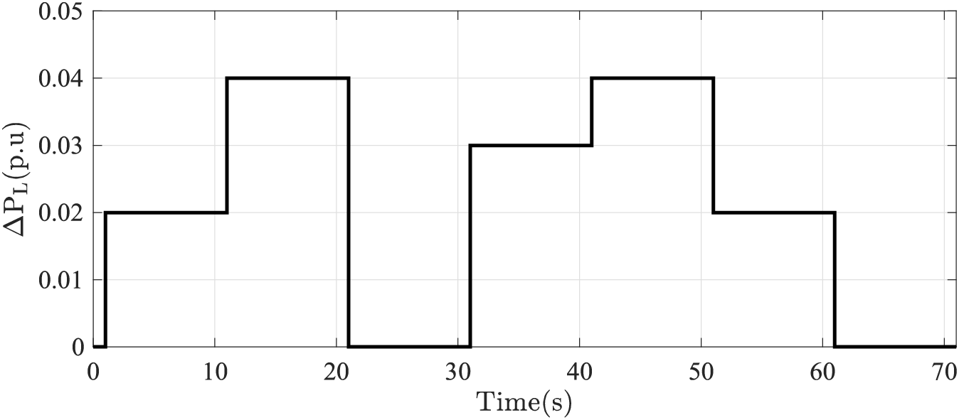
Figure 15:
Dynamic responses, depicted in Fig. 16 and Table 1, demonstrate that all controllers effectively manage the load perturbation. The most significant disturbance occurs at t = 21 s, with
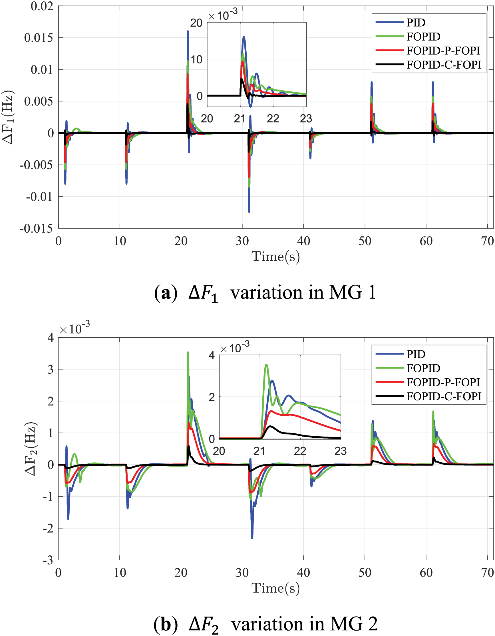
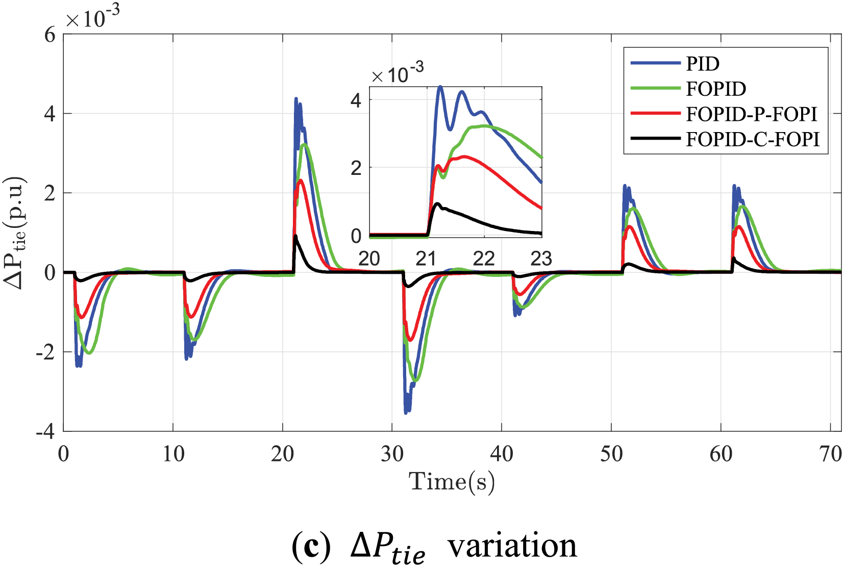
Figure 16: Responses of the interconnected MGs based on MSLP
4.2 Validation of the Optimal Parameters Search
In this study, the FOPID-C-FOPI and FOPID-P-FOPI controllers involve optimizing 16 parameters, denoted as nv = 16. In this subsection, we only consider the parameters selection of FOPID-C-FOPI controller.
The parameters are optimized using meta-heuristic algorithms, with the HBO method being the primary approach, benchmarked against particle swarm optimization (PSO), whale optimization algorithm (WOA) [36], and grey wolf optimizer (GWO) [37], hybrid grey wolf optimizer particle swarm optimization (HGWOPSO) [38]. Prior to Scenario 3, HBO is utilized to manage a case involving a 0.2 p.u. step load increase in MG 1, referred to as SLA. Fig. 14 demonstrates HBO’s effectiveness in parameter optimization, showcasing its convergent behavior across multiple controller configurations. This paper will subsequently compare the performance of HBO with other prevalent optimization algorithms.
Scenario 3 involves a 0.03 p.u. step load increase in MG 1 (see Fig. 1). For the FOPID-C-FOPI controllers, the parameters
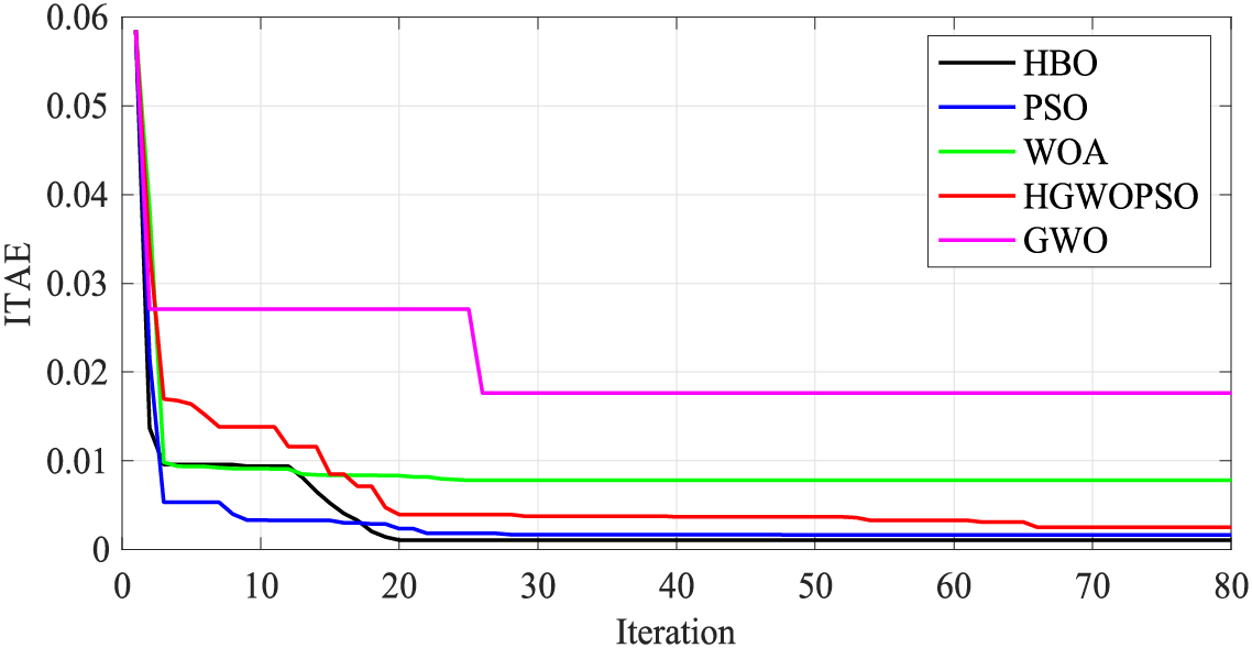
Figure 17: Performance of each algorithm for the FOPID-C-FOPI
4.3 Robustness Evaluation of the HBO-Based Controllers
This section assesses the robustness of the HBO-based FOPID-C-FOPI and FOPID-P-FOPI against system uncertainties, investigated in Scenarios 4–6. The original parameters of the MG 1 and MG 2 are described in Appendix A. In this subsection, the system perturbation is set as the power output fluctuations of WG, specifically under conditions where ∆γ = 0 or ∆v ≠ 0. With the output power reduction (in Fig. 18) of WG reaching 0.2 p.u. between 1 s and 10 s with wind speed noise described in Fig. 12, Scenario 4–6 are defined as follows:
Scenario 4 investigates a system of the interconnected MGs with inter-area synchronous torque coefficient
Scenario 5 investigates the same situation except for
Scenario 6 investigates a system with comprehensive parameter changes compared to the original system, as
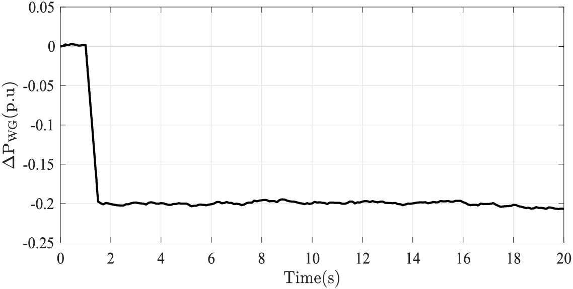
Figure 18:
The performance outcomes in Scenario 4, illustrated across Fig. 19a–c and Table 2, are designed to assess controller robustness under
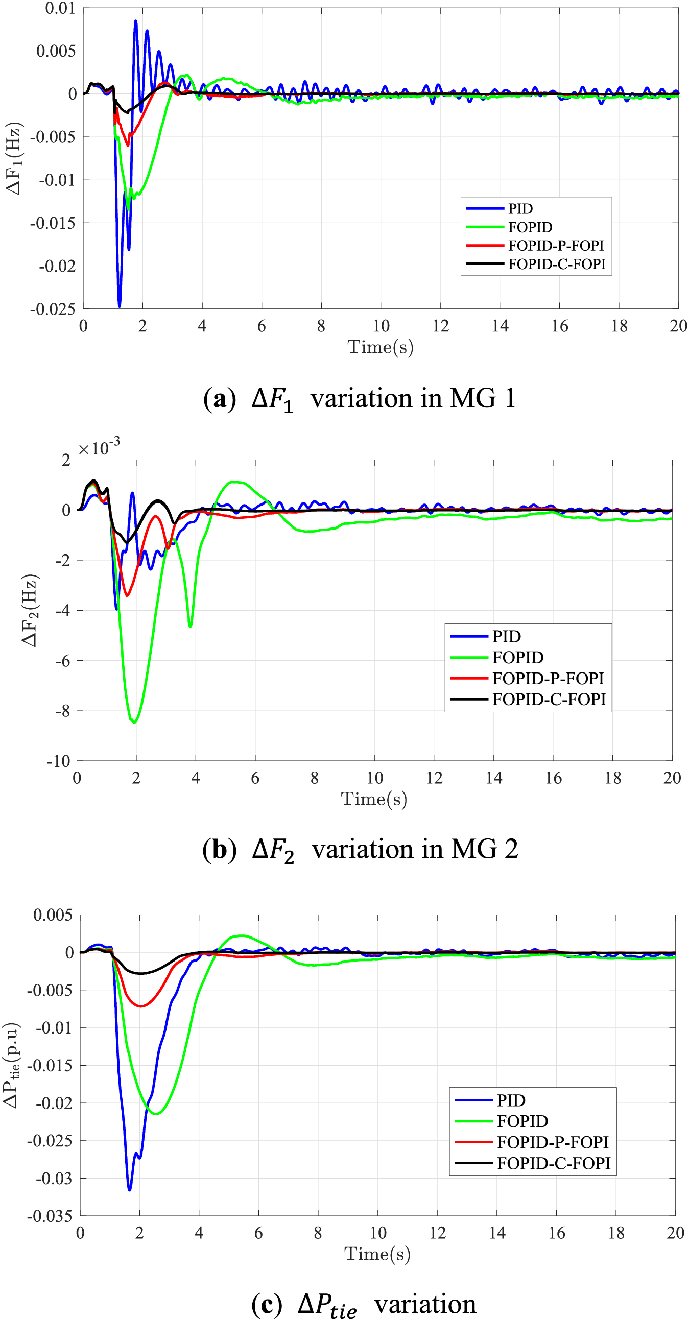
Figure 19: Responses of the interconnected MGs based on WG sudden decrease containing noise with 2T12

The results of Scenario 5 are illustrated in Fig. 20 and Table 2, which displays comparable performance to Scenario 4, where the
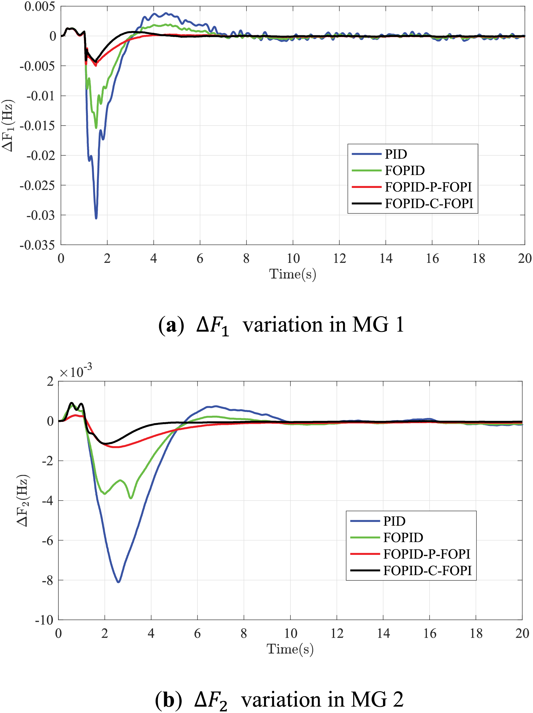
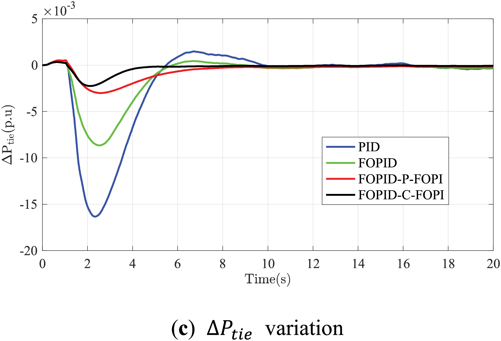
Figure 20: Responses of the interconnected MGs based on WG sudden decrease containing noise with 0.5T12
Further, the performance in Scenario 6, with multiple parameters tuned, shows strong robustness against system parameter changes with both FOPID-P-FOPI and FOPID-C-FOPI controllers in Fig. 21 and Table 2. The oscillation happens after load reduction with noise for PID and FOPID controllers.
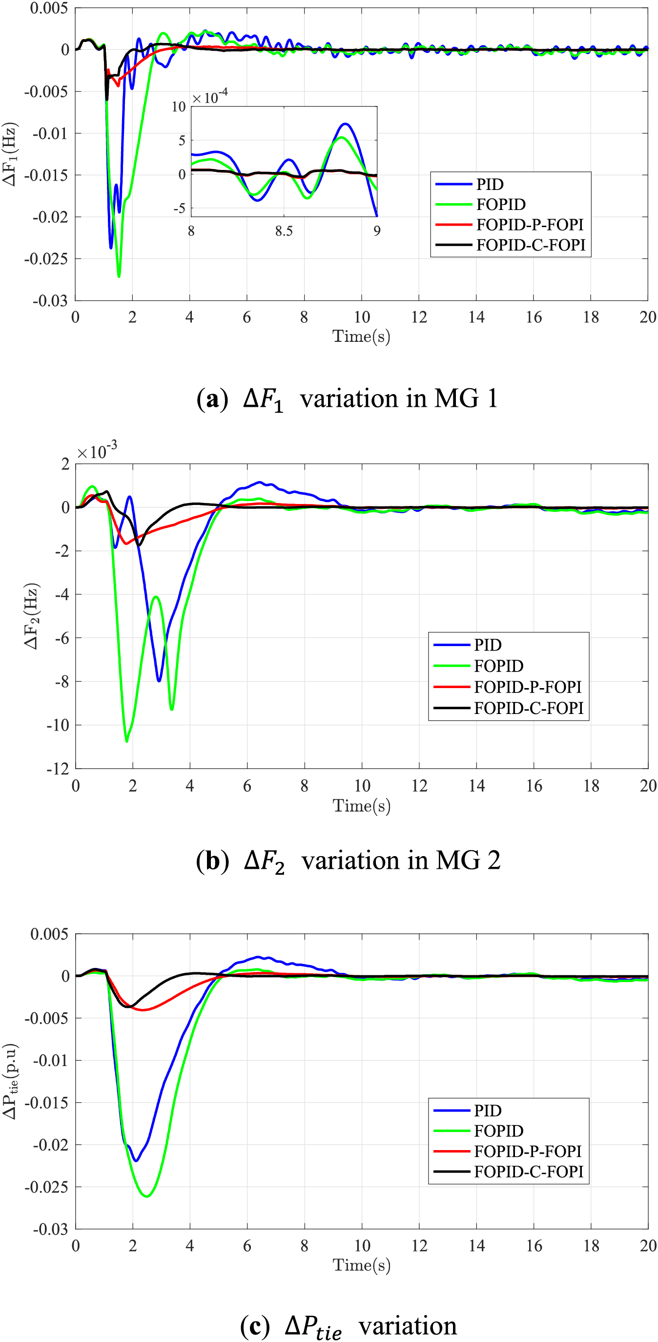
Figure 21: Responses of interconnected MGs based on WG sudden decrease containing noise with comprehensive power parameter changes
Figs. 19–21 illustrate that
The efficacy of the heap-based optimization (HBO) in selecting the controller parameters outweighs other traditional and novel heuristic-based optimization method, manifesting in convergency speed and error of ITAE. The robustness of the proposed back-up controllers demonstrates the system reliability for both frequency and tie-line power deviations. Scenarios 4–6 investigate the system responses under different interconnected microgrids systems with
This study substantiates the effectiveness of innovative dual-backup fractional order proportional integral derivative (FOPID) controllers, FOPID cascaded with fractional-order PI (FOPID-C-FOPI) and FOPID parallel fractional-order PI (FOPID-P-FOPI), in fortifying frequency and tie-line power stability within microgrids, particularly in the context of escalating renewable energy integration. Implemented within a two-area interconnected microgrid system, these controllers significantly outperform traditional PID and FOPID systems in managing dynamic fluctuations and disturbances. Comparative analyses confirm these advanced controllers’ superior performance and robustness, further enhanced by an optimization algorithm that surpasses conventional artificial intelligence methods in efficiency and precision. Adopting a dual-controller scheme boosts system resilience and ensures operational continuity through mutual backup functionality. This research highlights the critical role of advanced control mechanisms in adapting microgrid operations to the rapidly evolving energy sector, providing reliability and stability amidst diverse and intermittent energy inputs. Future studies will focus on expanding the scope to include simultaneous disturbances in multiple microgrids and exploring the responsive characteristics of flexible load consumers.
Acknowledgement: None.
Funding Statement: The authors received no specific funding for this study.
Author Contributions: The authors confirm contribution to the paper as follows: study conception and design: Aijia Ding; data collection: Aijia Ding; analysis and interpretation of results: Aijia Ding and Tingzhang Liu; draft manuscript preparation: Aijia Ding. All authors reviewed the results and approved the final version of the manuscript.
Availability of Data and Materials: Data sharing is not applicable to this article as no datasets were generated or analyzed during the current study.
Ethics Approval: Not applicable.
Conflicts of Interest: The authors declare that they have no conflicts of interest to report regarding the present study.
References
1. G. Magdy, E. A. Mohamed, G. Shabib, A. A. Elbaset, and Y. Mitani, “Microgrid dynamic security considering high penetration of renewable energy,” Prot. Contr. Mod. Pow., vol. 3, no. 1, pp. 1–11, Jul. 2018. doi: 10.1186/s41601-018-0093-1. [Google Scholar] [CrossRef]
2. H. H. Alhelou, P. Siano, M. Tipaldi, R. Ier-volino, and F. Mahfoud, “Primary frequency response improvement in interconnected power systems using electric vehicle virtual power plants,” World Electr. Veh. J., vol. 11, no. 2, May 2020, Art. no. 40. doi: 10.3390/wevj11020040. [Google Scholar] [CrossRef]
3. S. Kumari and G. Shankar, “Novel application of integral-tilt-derivative controller for performance evaluation of load frequency control of interconnected power system,” IET Gener. Transm. Dis., vol. 12, no. 14, pp. 3550–3560, Jun. 2018. doi: 10.1049/iet-gtd.2018.0345. [Google Scholar] [CrossRef]
4. M. Ahmed, G. Magdy, M. Khamies, and S. Kamel, “Modified TID controller for load frequency control of a two-area inter-connected diverse-unit power system,” Int. J. Elec. Power, vol. 135, Feb. 2022, Art. no. 107528. doi: 10.1016/j.ijepes.2021.107528. [Google Scholar] [CrossRef]
5. L. Dritsas, E. Kontouras, E. Vlahakis, I. Kitsios, G. Halikias and A. Tzes, “Modelling issues and aggressive robust load frequency control of interconnected electric power systems,” Int. J. Control, vol. 95, no. 3, pp. 753–767, Sep. 2022. doi: 10.1080/00207179.2020.1821248. [Google Scholar] [CrossRef]
6. G. K. Suman, J. M. Guerrero, and O. P. Roy, “Robust frequency control in interconnected microgrids: An H2/H∞ control approach,” IEEE Syst. J., vol. 16, no. 2, pp. 2044–2055, Sep. 2021. doi: 10.1109/JSYST.2021.3108685. [Google Scholar] [CrossRef]
7. D. Yanget et al., “Inertia-adaptive model predictive control-based load frequency control for interconnected power systems with wind power,” IET Gener. Transm. Dis., vol. 14, no. 22, pp. 5029–5036, Jul. 2020. doi: 10.1049/iet-gtd.2020.0018. [Google Scholar] [CrossRef]
8. M. H. Fini and M. E. H. Golshan, “Determining optimal virtual inertia and frequency control parameters to preserve the frequency stability in islanded microgrids with high penetration of renewables,” Electr. Pow. Syst. Res., vol. 154, pp. 13–22, Jan. 2018. doi: 10.1016/j.epsr.2017.08.007. [Google Scholar] [CrossRef]
9. Y. Arya, “Effect of electric vehicles on load frequency control in interconnected thermal and hydrothermal power systems utilizing CF-FOIDF controller,” IET Gener. Transm. Dis., vol. 14, no. 14, pp. 2666–2675, May 2020. doi: 10.1049/iet-gtd.2019.1217. [Google Scholar] [CrossRef]
10. E. Çelik, N. Öztürk, Y. Arya, and C. Ocak, “(1 + PD)-PID cascade controller design for performance betterment of load frequency control in diverse electric power systems,” Neural Comput. Appl., vol. 33, no. 22, pp. 15433–15456, Nov. 2021. doi: 10.1007/s00521-021-06168-3. [Google Scholar] [CrossRef]
11. D. Murugesan, K. Jagatheesan, P. Shah, and R. Sekhar, “Fractional order PIλDμ controller for microgrid power system using cohort intelligence optimization,” Res. Control Optim., vol. 11, Jun. 2023, Art. no. 100218. doi: 10.1016/j.rico.2023.100218. [Google Scholar] [CrossRef]
12. H. Abubakr, T. H. Mohamed, M. M. Hussein, J. M. Guerrero, and G. Agundis-Tinajero, “Adaptive frequency regulation strategy in multi-area microgrids including renewable energy and electric vehicles supported by virtual inertia,” Int. J. Elec. Power, vol. 129, Jul. 2021, Art. no. 106814. doi: 10.1016/j.ijepes.2021.106814. [Google Scholar] [CrossRef]
13. S. Oshnoei, M. R. Aghamohammadi, S. Oshnoei, S. Sahoo, A. Fathollahi and M. H. Khooban, “A novel virtual inertia control strategy for frequency regulation of islanded microgrid using two-layer multiple model predictive control,” Appl. Energ., vol. 343, Aug. 2023, Art. no. 121233. doi: 10.1016/j.apenergy.2023.121233. [Google Scholar] [CrossRef]
14. S. Sondhi and Y. V. Hote, “Fractional order PID controller for load frequency control,” Energ. Convers. Manage., vol. 85, pp. 343–353, Sep. 2014. doi: 10.1016/j.enconman.2014.05.091. [Google Scholar] [CrossRef]
15. E. M. Ahmed et al., “Improving load frequency control performance in interconnected power systems with a new optimal high degree of freedom cascaded FOTPID-TIDF controller,” Ain Shams Eng. J., vol. 14, no. 10, Oct. 2023, Art. no. 102207. doi: 10.1016/j.asej.2023.102207. [Google Scholar] [CrossRef]
16. M. Bhuyan, D. C. Das, and A. K. Barik, “Chaotic butterfly optimization algorithm based cascaded PI-TID controller for frequency control in three area hybrid microgrid system,” Optim. Contr. Appl. Met., vol. 44, no. 5, pp. 2595–2619, Mar. 2023. doi: 10.1002/oca.2994. [Google Scholar] [CrossRef]
17. M. Bhuyan, D. C. Das, and A. K. Barik, “Proficient power control strategy for combined solar gas turbine-wind turbine generator-biodiesel generator based two area interconnected microgrid employed with DC link using Harris’s hawk optimization optimised tilt-integral-derivative controller,” Int. J. Numer. Model. El., vol. 35, no. 4, Feb. 2022, Art. no. e2991. doi: 10.1002/jnm.2991. [Google Scholar] [CrossRef]
18. A. Latif, S. M. S. Hussain, D. C. Das, and T. S. Ustun, “State-of-the-art of controllers and soft computing techniques for regulated load frequency management of single/multi-area traditional and renewable energy-based power systems,” Appl. Energ., vol. 266, May 2020, Art. no. 114858. doi: 10.1016/j.apenergy.2020.114858. [Google Scholar] [CrossRef]
19. S. Sondhi and Y. V. Hote, “Fractional order PID controller for perturbed load frequency control using kharitonov’s theorem,” Int. J. Elec. Power, vol. 78, pp. 884–896, Jun. 2016. doi: 10.1016/j.ijepes.2015.11.103. [Google Scholar] [CrossRef]
20. A. Zamani, S. M. Barakati, and S. Yousofi-Darmian, “Design of a fractional order pid controller using gbmo algorithm for load-frequency control with governor saturation consideration,” ISA Trans., vol. 64, pp. 56–66, Sep. 2016. doi: 10.1016/j.isatra.2016.04.021. [Google Scholar] [PubMed] [CrossRef]
21. B. Kumar and S. Bhongade, “Load disturbance rejection based pid controller for frequency regulation of a microgrid,” in Proc. PESTSE, Bengaluru, India, Jul. 2016, pp. 1–6. doi: 10.1109/PESTSE.2016.7516459. [Google Scholar] [CrossRef]
22. Q. Askari, M. Saeed, and I. Younas, “Heap-based optimizer inspired by corporate rank hierarchy for global optimization,” Expert Syst. Appl., vol. 161, Dec. 2020, Art. no. 113702. doi: 10.1016/j.eswa.2020.113702. [Google Scholar] [CrossRef]
23. G. K. Suman and O. P. Roy, “Microgrid system for a rural area-an analysis of homer optimised model using MATLAB,” in Proc. RDCAPE, Noida, India, 2019, pp. 534–539. doi: 10.1109/RDCAPE47089.2019.8979097. [Google Scholar] [CrossRef]
24. D. Lee and L. Wang, “Small-signal stability analysis of an autonomous hybrid renewable energy power generation/energy storage system part I: Time-domain simulations,” IEEE Trans. Energy Conver., vol. 23, no. 1, pp. 311–320, Feb. 2008. doi: 10.1109/TEC.2007.914309. [Google Scholar] [CrossRef]
25. M. H. Khooban and M. Gheisarnejad, “A novel deep reinforcement learning controller based type-II fuzzy system: Frequency regulation in microgrids,” IEEE Trans. Emerg. Top. Comput. Intell., vol. 5, no. 4, pp. 689–699, Jan. 2020. doi: 10.1109/TETCI.2020.2964886. [Google Scholar] [CrossRef]
26. Y. Wang, Z. Sun, X. Li, X. Yang, and Z. Chen, “A comparative study of power allocation strategies used in fuel cell and ultracapacitor hybrid systems,” Energy, vol. 189, Dec. 2019, Art. no. 116142. doi: 10.1016/j.energy.2019.116142. [Google Scholar] [CrossRef]
27. A. Abazari, H. Monsef, and B. Wu, “Coordination strategies of distributed energy resources including FESS, DEG, FC and WTG in load frequency control (LFC) scheme of hybrid isolated micro-grid,” Int. J. Elec. Power, vol. 109, pp. 535–547, Jul. 2019. doi: 10.1016/j.ijepes.2019.02.029. [Google Scholar] [CrossRef]
28. M. I. Ibraheem, M. Edrisi, M. Gholipour, and H. H. Alhelou, “A novel frequency regulation in islanded microgrid using sliding mode control with disturbance observers considering storages and EVs,” Comput. Electr. Eng., vol. 105, Jan. 2023, Art. no. 108537. doi: 10.1016/j.compeleceng.2022.108537. [Google Scholar] [CrossRef]
29. P. Indranil and S. Das, “Kriging based surrogate modeling for fractional order control of microgrids,” IEEE Trans. Smart Grid, vol. 6, no. 1, pp. 36–44, Jul. 2014. doi: 10.1109/TSG.2014.2336771. [Google Scholar] [CrossRef]
30. H. Bevrani, F. Habibi, P. Babahajyani, M. Watanabe, and Y. Mitani, “Intelligent frequency control in an ac microgrid: Online pso-based fuzzy tuning approach,” IEEE Trans. Smart Grid, vol. 3, no. 4, pp. 1935–1944, Jun. 2012. doi: 10.1109/TSG.2012.2196806. [Google Scholar] [CrossRef]
31. S. Mokhtar and A. M. Alsseid, “Cascade of fractional order PID based PSO algorithm for LFC in two-area power system,” in Proc. ICERA, Yogyakarta, Indonesia, 2021, pp. 1–6. doi: 10.1109/ICERA53111.2021.9538646. [Google Scholar] [CrossRef]
32. M. Javad, K. Zare, and M. T. Hagh, “Applying fractional order PID to design TCSC-based damping controller in coordination with automatic generation control of interconnected multi-source power system,” Eng. Sci. Technol., vol. 20, no. 1, pp. 1–17, Feb. 2017. doi: 10.1016/j.jestch.2016.06.002. [Google Scholar] [CrossRef]
33. I. Pan and S. Das, “Chaotic multi-objective optimization based design of fractional order PIλDμ controller in AVR system,” Int. J. Electr. Power, vol. 43, no. 1, Dec. 2012, Art. no. 393407. doi: 10.1016/j.ijepes.2012.06.034. [Google Scholar] [CrossRef]
34. S. Debbarma, L. C. Saikia, and N. Sinha, “AGC of a multi-area thermal system under deregulated environment using a non-integer controller,” Electr. Pow. Syst. Res., vol. 95, pp. 175–183, Feb. 2013. doi: 10.1016/j.epsr.2012.09.008. [Google Scholar] [CrossRef]
35. J. C. Vinitha, G. Ramadas, and P. U. Rani, “PSO based fuzzy logic controller for load frequency control in EV charging station,” J. Electr. Eng. Technol., vol. 19, no. 1, pp. 193–208, Jul. 2023. doi: 10.1007/s42835-023-01568-y. [Google Scholar] [CrossRef]
36. P. C. Sahu, R. C. Prusty, and S. Panda, “Frequency regulation of an electric vehicle-operated micro-grid under WOA-tuned fuzzy cascade controller,” Int. J. Ambient Energy, vol. 43, no. 1, pp. 2900–2911, 2022. doi: 10.1080/01430750.2020.1783358. [Google Scholar] [CrossRef]
37. B. Kumar, S. Adhikari, S. Datta, and N. Sinha, “Real time simulation for load frequency control of multisource microgrid system using grey wolf optimization based modified bias coefficient diagram method (GWO-MBCDM) controller,” J. Electr. Eng. Technol., vol. 16, no. 1, pp. 205–221, Nov. 2020. doi: 10.1007/s42835-020-00596-2. [Google Scholar] [CrossRef]
38. M. A. Shaheen, H. M. Hasanien, and A. Alkuhayli, “A novel hybrid GWO-PSO optimization technique for optimal reactive power dispatch problem solution,” Ain Shams Eng. J., vol. 12, no. 1, pp. 621–630, Mar. 2021. doi: 10.1016/j.asej.2020.07.011. [Google Scholar] [CrossRef]
39. Y. Pan, X. Liu, W. J. Zhu, and H. X. Lin, Power Quality-Frequency Deviation for Power System. Beijing, China: China Standards Press, 2008. [Google Scholar]

Cite This Article
 Copyright © 2024 The Author(s). Published by Tech Science Press.
This work is licensed under a Creative Commons Attribution 4.0 International License , which permits unrestricted use, distribution, and reproduction in any medium, provided the original work is properly cited.


 Submit a Paper
 Propose a Special lssue
 View Full Text
 Download PDF
 Downloads
 Citation Tools