
 Submit a Paper
 Propose a Special lssue
 Open Access
ARTICLE

Improved Strategy of Grid-Forming Virtual Synchronous Generator Based on Transient Damping
1 Key Laboratory of Advanced Manufacturing and Automation Technology, Education Department of Guangxi Zhuang Autonomous Region, Guilin University of Technology, Guilin, 541006, China
2 Key Laboratory of Modern Power System Simulation and Control & Renewable Energy Technology, Ministry of Education, Northeast Electric Power University, Jilin, 132011, China
* Corresponding Author: Rongliang Shi. Email:
(This article belongs to the Special Issue: Emerging Technologies for Future Smart Grids)
Energy Engineering 2024, 121(11), 3181-3197. https://doi.org/10.32604/ee.2024.054485
Received 29 May 2024; Accepted 30 July 2024; Issue published 21 October 2024
 View Full Text
 Download PDF
Abstract
The grid-forming virtual synchronous generator (GFVSG) not only employs a first-order low-pass filter for virtual inertia control but also introduces grid-connected active power (GCAP) dynamic oscillation issues, akin to those observed in traditional synchronous generators. In response to this, an improved strategy for lead-lag filter based GFVSG (LLF-GFVSG) is presented in this article. Firstly, the grid-connected circuit structure and control principle of typical GFVSG are described, and a closed-loop small-signal model for GCAP in GFVSG is established. The causes of GCAP dynamic oscillation of GFVSG under the disturbances of active power command as well as grid frequency are analyzed. On this basis, the LLF-GFVSG improvement strategy and its parameter design method are given. Finally, the efficiency of the proposed control strategy in damping GCAP dynamic oscillations under various disturbances is verified using MATLAB simulations and experimental comparison results.Keywords
Nomenclature
| Abbreviations | |
| GFVSG | Grid-forming virtual synchronous generator |
| GCAP | Grid-connected active power |
| LLF-GFVSG | Lead-lag filter based GFVSG |
| RESs | Renewable energy sources |
| PECs | Power electronic converters |
| PEDPSs | Power electron dominated power systems |
| TSG | Traditional synchronous generator |
| Parameters and Constants | |
| Udc | DC side voltage |
| Ug | The amplitude of ugabc |
| Zline | Line impedance |
| Cf | Filter capacitor |
| θ | Output phase angle |
| ugabc | Three-phase network voltage |
| iabc | Grid-connected current |
| ω0 | Rated angular frequency |
| ωg | Angular frequency of ugabc |
| X | Equivalent reactance of Zline |
| ∆ | The amount of perturbation/fluctuation |
| Variables | |
| Pe | Grid-connected active power |
| Pref | Reference power |
| J | Virtual inertia |
| D | Virtual damping |
| ω | Output angular frequency |
| Qe | Grid-connected reactive power |
| Qref | Reference reactive power |
| E | Output voltage amplitude |
| E0 | Nominal voltage |
| kq | Proportional gain |
| K | Synchronous voltage coefficient |
| δ | Phase angle |
| E0 | Nominal voltage |
| ωn | Undamped oscillation frequency of second-order system |
| ξ | Damping ratio |
| ∆Pe0 | The GCAP steady state deviation |
| Kp | The forward compensation coefficient |
| Kd | The feedforward compensation coefficient |
In recent years, nations worldwide have confronted varying degrees of energy pressures: firstly, the challenge of securing adequate and reliable energy supplies at sustainable prices over the long term, and secondly, the profound and irreversible environmental damage resulting from excessive energy consumption. It is in this energy dilemma that a range of renewable energy sources (RESs) such as hydro, wind and solar, which have high resource potential and low environmental pollution, have begun to develop rapidly [1]. RES inevitably requires power electronic converters (PECs) as its grid-connected interface, which promotes the transformation of traditional power systems to power electron dominated power systems (PEDPSs) [2,3]. While PECs bring controllability as well as flexibility to PEDPS, they also bring some drawbacks, unfortunately, such as a significant reduction in inertia and damping levels, which leads to several stability problems, e.g., dynamic oscillations of active power and output frequency [4]. In order to eliminate the dynamic oscillations of PEDPS active power and output frequency caused by low inertia and weak damping, the grid-forming virtual synchronous generator (GFVSG) is proposed to provide sufficient inertia and damping support for PEDPS [5–7]. GFVSG simulates the rotor motion equation of a traditional synchronous generator (TSG), that is, it uses the first-order low-pass filter containing virtual inertia and virtual damping parameters to realize virtual inertia and virtual damping control, which helps to improve the PEDPS frequency stability [8,9].
It can be pointed out that the GFVSG, while realizing the virtual inertia control, makes its closed-loop control system of grid-connected active power (GCAP) into a typical second-order oscillation system, which is prone to lead to the dynamic oscillation phenomenon of GCAP similar to that of the TSG under the perturbations of active power command, grid frequency and so on [10,11]. The large fluctuating current existing in the GCAP dynamic oscillation of GFVSG is easy to cause the PEC with weak overload capability to shutdown due to the over-current protection or even hardware equipment to burn down, which reduces the reliability of GFVSG grid-connected operation system [12]. At present, the control methods applied to suppress or eliminate the dynamic oscillations of GCAP and output frequency of GFVSG mainly include adaptive parameter tuning scheme [13–16], dynamic feedback compensation method [17–20] and dynamic feedforward compensation approach [21–24].
Among them, the adaptive parameter tuning scheme optimizes the GCAP dynamic response performance of GFVSG by leveraging the fact that parameters such as virtual inertia, virtual damping, or virtual impedance of GFVSG can be flexibly adapted online without being restricted by the physical conditions. In [13], the virtual inertia parameter was adaptively adjusted according to the sign of the product of the GFVSG output angular frequency and the rate of change of the angular frequency to suppress the GCAP dynamic oscillation. In [14,15], an adaptive parameter tuning scheme by simultaneously and adaptively adjusting both the virtual inertia parameter and the virtual damping parameter was used to further achieve the optimization of the GCAP dynamic response performance of GFVSG. Reference [16], an adaptive virtual impedance adjustment method, was applied to the GFVSG grid-connected system to enhance the system’s ability to damp GCAP dynamic oscillations. It is noteworthy that the adaptive parameter tuning methods discussed in references [13–16] necessitate online modifications to the key parameters of GFVSG, thereby introducing nonlinear variation characteristics into the GFVSG grid-connected system. This complexity escalates the challenges of system parameter tuning and heightens the risk of operational instability.
Different from the adaptive parameter tuning scheme, the dynamic feedback compensation method and the dynamic feedforward compensation approach improve the GCAP dynamic response characteristics of GFVSG by reconfiguring the control loop of the GCAP closed-loop control system of GFVSG under the premise of ensuring that the key parameters of GFVSG remain unchanged. In [17,18], the differential feedback links based on the GCAP and the output angular frequency were introduced into the GFVSG control loop, respectively. However, the digital implementation of the differential algorithms contained in [17,18] would bring about the problems of high frequency harmonic interference. In [19], the GCAP proportional feedback link was replaced by using a proportional feedback link based on a lead-lag filter, which avoids differential manipulations but increases the control order of the GCAP closed control system. In [20], a first-order lag link based on the GCAP was added into the GFVSG feedback control loop, which has a similar control effect as in [19], but increases the difficulty of parameter design. It should be noted that the dynamic feedback compensation methods used in [17–20] can only produce the effect after the deviation of the feedback variables, and there is a certain passivity in the control implementation.
Different from the dynamic feedback compensation method, the dynamic feedforward compensation approach has some initiative in control effect. In [21], the GCAP differential feedforward link was added into the control loop of GFVSG, but the GCAP differential operation would inevitably introduce high frequency harmonic signals. In [22], an angular frequency feedforward link based on a lead-lag filter was added into the GFVSG control loop, which does not require differential operation, but increases the control order of the system as well as the difficulty of parameter design. In [23], a feedforward link based on the active power command was inserted into the control loop of GFVSG, which has the benefit of intuitive parameter design, but the parameter design depends on the line impedance parameters of the system. In [24], a phase-based dynamic feedforward compensation was proposed to optimize the GCAP dynamic response performance of GFVSG. The feedforward parameter design in [24] does not depend on the line impedance parameters, but the system suffers from a weakened ability to suppress high frequency interference signals.
To overcome the shortcomings of the above the dynamic feedback compensation methods and the dynamic feedforward compensation approaches, such as requiring differential operation, increasing control order and complex parameter design, an improved GFVSG based on lead-lag filter (LLF-GFVSG) is proposed in this paper. The remainder of this paper is organized as follows: Section 2 introduces the principle of GFVSG and analyzes the GCAP response characteristics. Section 3 proposes the LLF-GFVSG control strategy and provides a detailed parameter design method. Section 4 presents results of both simulation and experimental comparison. Finally, Section 5 concludes this paper.
2 Principle of GFVSG and Its GCAP Response Characteristics
2.1 Grid-Connected Structure of GFVSG and Its Control Principle
The GFVSG grid-connected circuit structure and its control principle are shown in Fig. 1 [11].
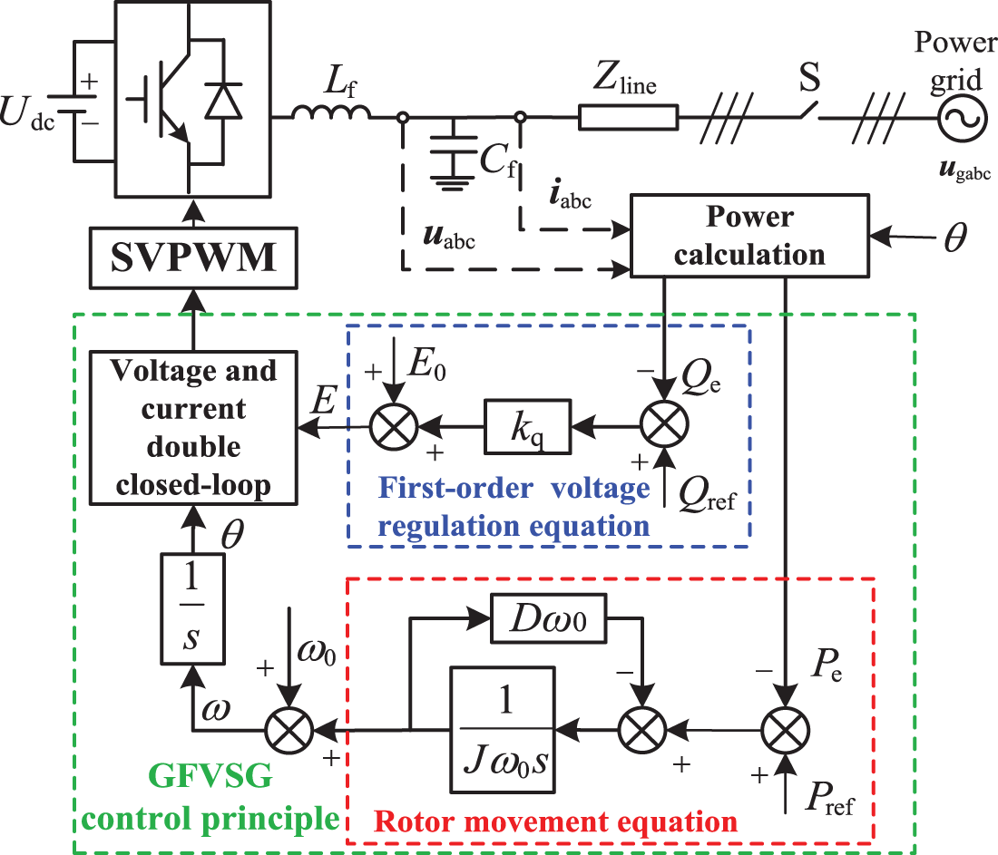
Figure 1: Grid-connected circuit structure and control principle of GFVSG
In Fig. 1, Udc denotes DC side voltage and Zline represents line impedance. Lf and Cf are filter inductance and filter capacitor; θ denotes output phase angle; ugabc and S are three-phase network voltage and grid-connected switch; uabc denotes three-phase output voltage and iabc represents grid-connected current. The rotor equations of motion of the GFVSG and its primary regulating voltage equation can be expressed sequentially as follows:
where Pe and Pref are GCAP and its reference power, respectively, and J, D are virtual inertia and virtual damping; ω and ω0 are output angular frequency and the fund-amental; Qe denotes grid-connected reactive power and Qref represents reference reactive power; E and E0 are output voltage amplitude and nominal voltage, respectively, and kq is a proportional gain.
It is worth noting that the primary focus of this paper lies in addressing the GCAP dynamic response optimization issue of GFVSG, considering the GCAP and the grid-connected reactive power can be decoupled under the condition that Zline is inductive and disregarding the impact of the voltage and current bottom double-closed-loop on the power outer-loop with a high control bandwidth. Thus, the relevant content concerning the reactive power control and the bottom double-loop control will not be reiterated [21].
2.2 Small-Signal Model and Characteristic Analysis of GFVSG
As illustrated in Fig. 1 and combined with the line power transfer theory, the Pe of GFVSG can be approximated by Eq. (3) [25].
where Ug is the amplitude of ugabc and ωg is the angular frequency of ugabc. X denotes the equivalent reactance of Zline; the synchronizing voltage coefficient is first formulated as K = 1.5UgE/X; δ and s are phase angle and laplacian. As shown in Fig. 2, the GCAP closed-loop small-signal control model of GFVSG can be derived from Eqs. (1) and (3). In Fig. 2, “∆” represents the amount of perturbation.
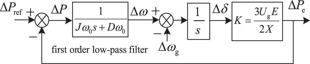
Figure 2: The GCAP closed-loop small-signal control model of GFVSG
From Fig. 2, it can be seen that while the GFVSG realizes the virtual inertia control by using the first-order low-pass filter 1/(Jω0s + Dω0) consisting of J and D, its Pe and ω are affected by ∆Pref and ∆ωg disturbances. The transfer functions of ∆Pref to ∆Pe, ∆ωg to ∆Pe, ∆Pref to ∆ω and ∆ωg to ∆ω for GFVSG are derived as follows:
According to Eqs. (4) and (5), it is easy to find that the GCAP closed-loop control system of GFVSG is a second-order oscillation system, and the corresponding natural oscillation angular frequency ωn and its damping ratio ξ of the system can be expressed as:
It can also be obtained from Eq. (4) that the GCAP steady state deviation ∆Pe0 (∆Pe0 = ∆Pe − ∆Pref) of GFVSG is shown in Eq. (7).
By applying Eqs. (6) and (7), it can be found that the value of J affects the ξ and ωn of the GFVSG grid-connected system at the same time, i.e., the larger J is, the smaller the corresponding ξ and ωn is, and the more pronounced the dynamic oscillation and the longer the dynamic response time of its GCAP under the disturbance of ∆Pref and ∆ωg. The value of D also affects ξ and ∆Pe0 of the GFVSG grid-connected system; that is, the larger the value of D, the larger the corresponding ξ and ∆Pe0 are, and the stronger the damping ability of GCAP dynamic oscillation, but the larger the GCAP steady state deviation of Pe when ωg deviates from ω0. Consequently, for the GFVSG grid-connected system, the values of J and D dominated the dynamic and steady state response performance of its GCAP. In other words, the values of J and D could only be reasonably determined on the premise of weighing the GCAP dynamic and steady state response performance of GFVSG, resulting in certain limitations in the optimization of its GCAP response performance.
3 LLF-GFVSG Improvement Strategy
To overcome the inherent limitations of the GFVSG, arising from its dependency on a first-order low-pass filter for optimizing both dynamic and steady-state response performance of the GCAP, as depicted in Fig. 1, we have substituted the virtual inertia control component with a lead-lag filter. This results in the development and proposition of an enhanced LLF-GFVSG control strategy. This innovative approach not only provides the advantages of active control but also obviates the necessity for differential operations, preserves a second-order control framework, and simplifies the parameter design process. Additionally, it provides the parameter design methodology for LLF-GFVSG.
3.1 Control Principle of LLF-GFVSG
Fig. 3a shows the GCAP closed-loop small-signal control model of LLF-GFVSG. In Fig. 3a, Kp and Kd are the forward compensation coefficient and feedforward compensation coefficient of LLF-GFVSG, respectively. Further, the GCAP closed-loop small-signal equivalent control model of LLF-GFVSG can be obtained by equivalent transformation of the control block diagram in Fig. 3a, as shown in Fig. 3b. Since LLF composed of J, D, Kp and Kd is included in Fig. 3b, the improved strategy is referred to as LLF-GFVSG for short in this text.
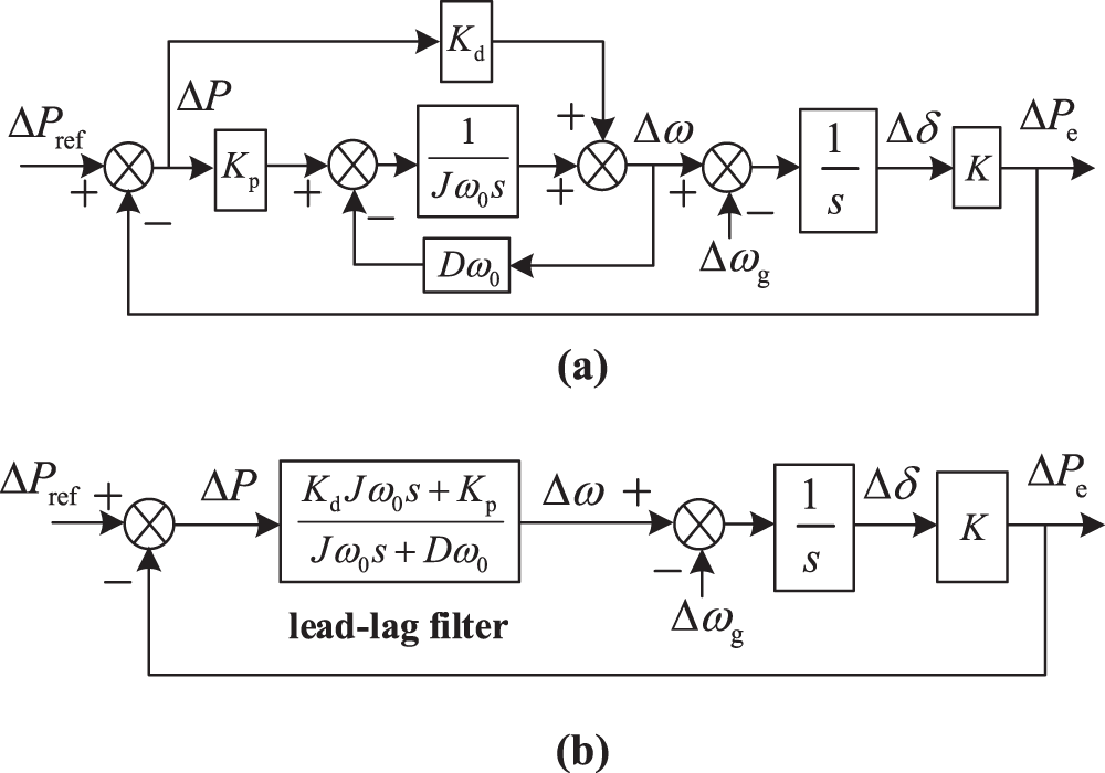
Figure 3: The GCAP closed-loop small-signal control model of LLF-GFVSG. (a) Control model of LLF-GFVSG. (b) Equivalent control model of LLF-GFVSG
According to Fig. 3a,b, the transmission functions of ∆Pref to ∆Pe, ∆ωg to ∆Pe, ∆Pref to ∆ω and ∆ωg to ∆ω for LLF-GFVSG can be expressed as:
It was comparing Eqs. (8) with (4) and Eqs. (9) with (5), respectively, it can be found that, compared with the GFVSG, the LLF-GFVSG, under the premise of ensuring that the order of its GCAP closed-loop control system remains unchanged and is still a second-order system, transforms the natural oscillating angular frequency of its grid-connected system, ωn1, and its damping ratio, ξ1, in turn, as follows:
From Eq. (8), the GCAP steady state deviation ∆Pe01 of LLF-GFVSG is obtained, as shown in Eq. (11).
By comparing Eqs. (10) with (6) and Eqs. (11) with (7), respectively, it can be found that the value of Kp affects ωn1, ξ1 and ∆Pe01 of the LLF-GFVSG grid-connected system at the same time, in order to prioritize to ensure that the GCAP of LLF-GFVSG does not generate steady state deviation under the condition of ωg deviation from ω0, i.e., to prioritize to satisfy the condition of ∆Pe01 = ∆Pe0, the paper needs to set Kp = 1, then we have ωn1 = ωn, which then ensures that the grid-connected systems of LLF-GFVSG and GFVSG have the same natural oscillation angular frequency, which provides a fair condition for comparing the GCAP dynamic and steady state response performances of LLF-GFVSG and GFVSG, and at the same time simplifies the process of parameter design of LLF-GFVSG.
3.2 Parameter Design of LLF-GFVSG
With the theoretical analysis in the previous subsection and the setting of Kp = 1 (∆Pe01 = ∆Pe0 with ωn1 = ωn), Eq. (10) can be equated as:
Comparing Eqs. (12) and (6), it is easy to see that LLF-GFVSG has one more Kd control degree of freedom than GFVSG, that is, the former can optimize its GCAP dynamic response performance directly by selecting a reasonable Kd value. It can also be seen from Eq. (8) that G11(s) of LLF-GFVSG is a second-order control system containing negative real zeros under the condition of Kd > 0. With reference to the parameter design method given in [25], G11(s) can be equivalent transformed into:
As can be seen from Eq. (13), the GCAP response of LLF-GFVSG mainly includes two parts: differential dynamic response and zero-free typical second-order system response. If Kd is larger, the negative real zero z0 = −1/(KdJω0) of G11(s) will be closer to the origin. The effect of differential dynamic response on the GCAP dynamic response of LLF-GFVSG is more obvious. At the same time, to suppress the GCAP dynamic oscillation of LLF-GFVSG, it is necessary to adjust the value of Kd to make ξ1 ≥ 1, and when ξ1 ≥ 1, it can further ensure that there is no power overshot in the dynamic response process of the zero-free typical second-order system in G11(s).
On the one hand, under the condition that ξ1 is ≥1, it can be obtained by Eq. (12):
On the other hand, under the condition that the value of Kd satisfies Eq. (14), regardless of the fact that the two negative real poles s1 and s2 of the second-order system with negative real zeros are different or the same, if z0 is at the right end of s1 and s2, i.e., if z0 is closer to the origin and corresponds to the Kd obtaining a larger value. The differential dynamic response part of G11(s) will have a significant impact on the GCAP dynamic response of LLF-GFVSG and even introduce power overshooting [26]. Given this, it is recommended to select the z0 of G11(s) in the range s1 to s2, that is:
According to Eqs. (12), (14) and (15) as well as the main parameters of the GFVSG, the rationalization of the Kd parameters of the additional control degrees of freedom of the LLF-GFVSG can be accomplished.
4 Simulation and Experimental Test Results
4.1 Comparative Analysis of Simulation Results
To verify the correctness and effectiveness of the LLF-GFVSG improvement strategy and its parameter design method, the 100kVA-GFVSG grid-connected system simulation model as shown in Fig. 1, is built by means of MATLAB simulation program. In the simulation process, Pref = 0 kW, J = 6 kg·m2, D = 50.66, Kp = 1 for 100kVA-GFVSG is set. Other main simulation parameters for 100kVA-GFVSG are shown in Table 1 [11].
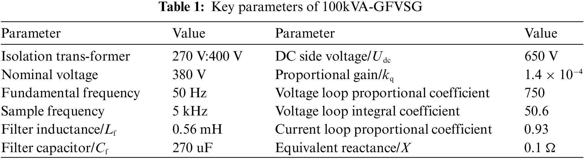
At the same time, according to the main parameters given in Table 1 can be calculated to get K = 1,452,000, ωn = ωn1 = 27.7 rad/s, ξ = 0.15 < 1, and need to set Kd ≥ 3.24 × 10⁻⁵ to ensure that ξ1 ≥ 1, in this case, Kd = 5.3 × 10⁻⁵ is selected, and thus there is ξ1 = 1.52 > 1, z0 = −10, the s1 = −75, s2 = −10. It is worth pointing out that in Fig. 3a, Kd is multiplied by ∆P and then feedforward compensated to ∆ω, and for the 100kVA-GFVSG grid-connected system, usually ∆P (order of magnitude 105)>>∆ω (unit of the order of magnitude), so that if the two reach a comparable order of magnitude, it is necessary for Kd to take a magnitude of 10−5 values.
By inputting the aforementioned parameters into Eqs. (8) and (9), Bode plots comparing the frequency response characteristics of ∆Pe/∆Pref, ∆Pe/∆ωg, ∆ω/∆Pref and ∆ω/∆ωg for LLF-GFVSG, GFVSG (D = 50.66 J/rad) and GFVSG (D = 335.16 J/rad) are presented in Fig. 4.
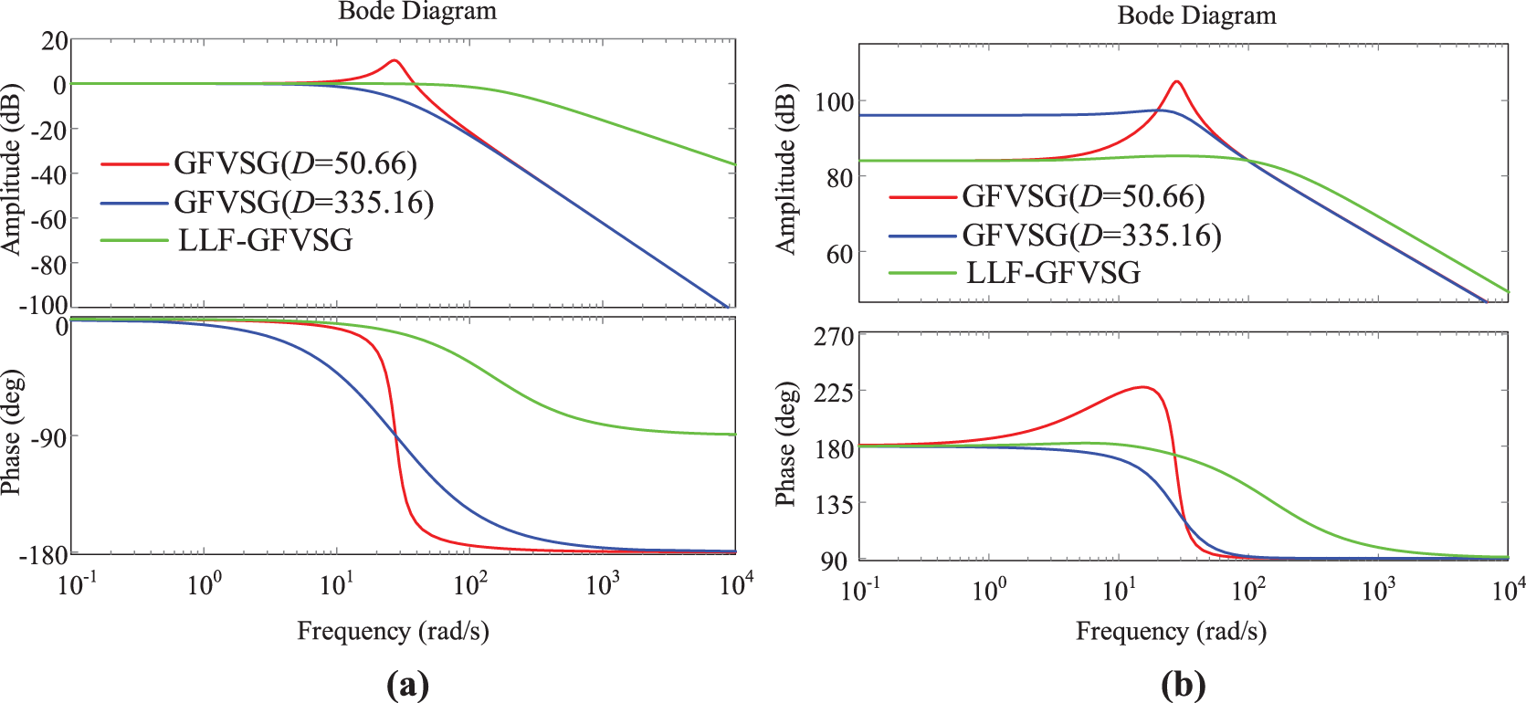
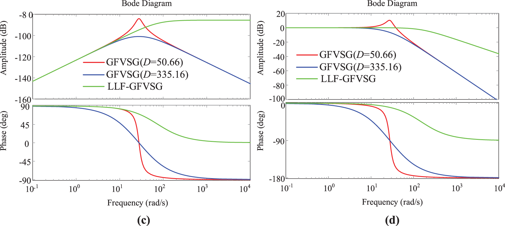
Figure 4: Frequency response comparison of LLF-GFVSG and GFVSG. (a) ∆Pe/∆Pref. (b) ∆Pe/∆ωg. (c) ∆ω/∆Pref. (d) ∆ω/∆ωg
Fig. 5 shows the simulation comparison results of Pe vs. output frequency f for LLF-GFVSG, GFVSG (D = 50.66) and GFVSG (D = 335.16), respectively, in response to the dynamic process of the Pref stepping from 20 to 60 kW and the grid frequency fg stepping from 50 to 49.95 Hz.
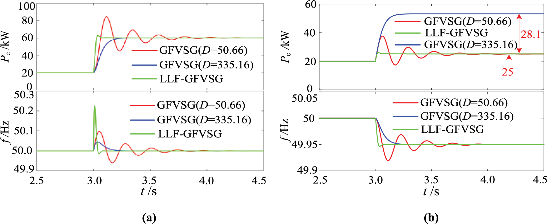
Figure 5: Comparative simulation results under Pref step and fg step. (a) Pref step. (b) fg step
It is not difficult to see from Figs. 4 and 5 that when D = 50.66, GFVSG is ξ = 0.15 of the underdamped system. The four bode diagrams representing GFVSG (D = 50.66) shown in Fig. 4 all have a resonant peak before the cutoff frequency. Therefore, its Pe and f under both the Pref and fg disturbances appear dynamic oscillations. When D = 335.16 is increased, GFVSG is an overdamped system ξ = 1.006, and the four bode diagrams representing GFVSG (D = 335.16) shown in Fig. 4 do not have a resonance peak before the cutoff frequency, so Pe and f do not oscillate dynamically under Pref and fg disturbances. However, its Pe introduces active steady state deviation at fg = 49.95 Hz (∆Pe0 = 28.1 kW); while the Pe and f of LLF-GFVSG do not show dynamic oscillations under the two perturbations of Pref and fg, and its Pe does not have active steady state deviation at fg = 49.95 Hz (∆Pe01 = 0) as shown in Fig. 5.
Fig. 6 presents the simulation results of the Pe and f during the implementation of the FOVSG control method in reference [27], as well as the active reference command Pref of LLF-GFVSG transitioning from 20 to 60 kW and power grid frequency fg varying from 50 to 49.95 Hz under the identical conditions. As illustrated in Fig. 6, the LLF-GFVSG and FOVSG exhibit comparable dynamic performance in terms of active power Pe under disturbances in Pref and fg. However, the output frequency overshoot observed in FOVSG is significantly higher than that in LLF-GFVSG. During the fg step change, the output frequency response f of LLF-GFVSG is observed to be slower than that of FOVSG, suggesting a superior inertia response in LLF-GFVSG compared to FOVSG.
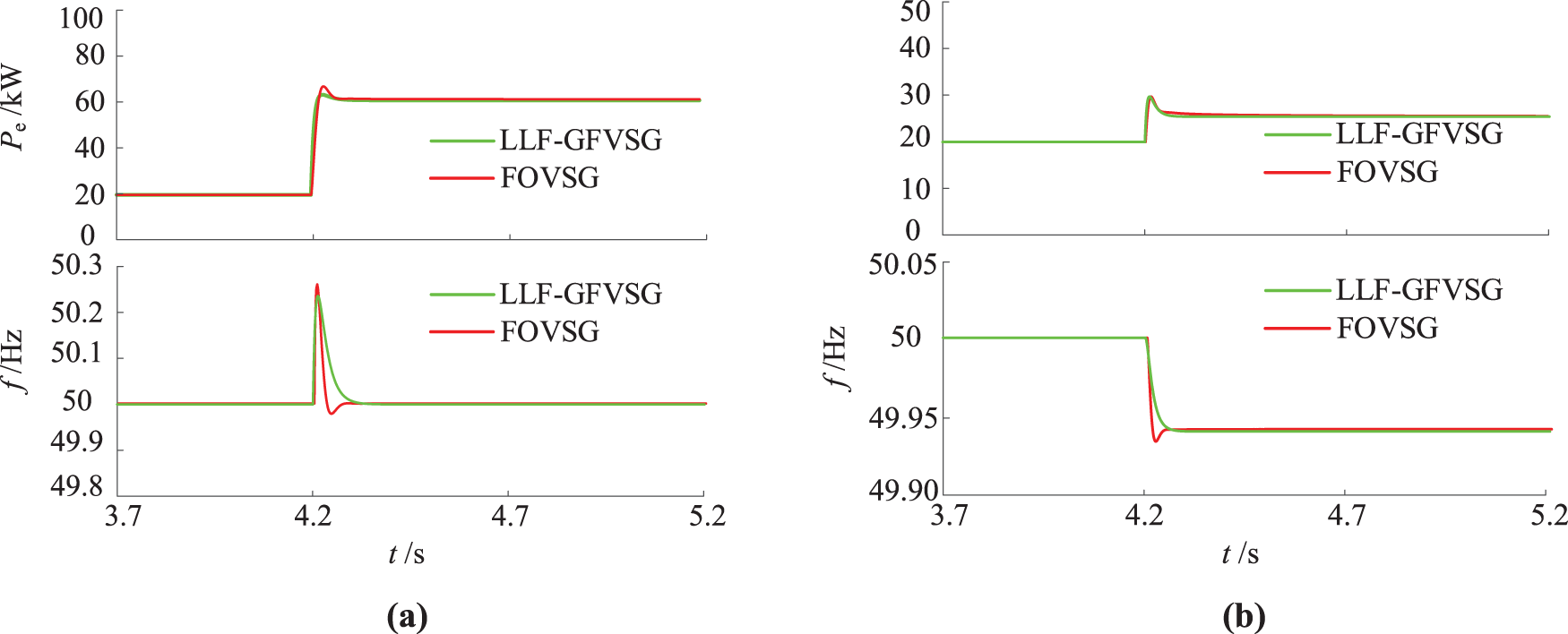
Figure 6: Comparison of simulation results between LLF-GFVSG and FOVSG. (a) Pref step. (b) fg step
In summary, the LLF-GFVSG can effectively solve the problem that it is challenging to balance the GCAP dynamic response performance and its steady state response performance of GFVSG under both the disturbances of Pref and fg, i.e., the LLF-GFVSG can ensure that its Pe has both good dynamic and steady state response performance under the two disturbances of Pref and fg. It should be noted that since the LLF-GFVSG directly utilizes ∆P to feedforward compensate ∆ω, and there is a large deviation between Pref and Pe at the beginning of the disturbance, i.e., the dynamic feedforward compensation to ∆ω is larger, so while improving the dynamic response speed of Pe, it is also easy to cause a large overshoot amplitude of f under the disturbance of Pref.
4.2 Experimental Comparison Results and Analysis
In order to further verify the efficacy and superiority of the described LLF-GFVSG over the GFVSG in optimizing its GCAP dynamic response performance, experimental comparative verification is carried out on the energy storage microgrid system test platform presented in Fig. 7. The testing platform mainly includes two 100kVA-GFVSGs, two 100kVA bi-directional controllable rectifiers that provide a stable DC voltage and bi-directional energy supply for the 100kVA-GFVSGs (which can be used as a storage battery simulator), and a set of 250 kW resistive controllable loads and the distribution network [25].
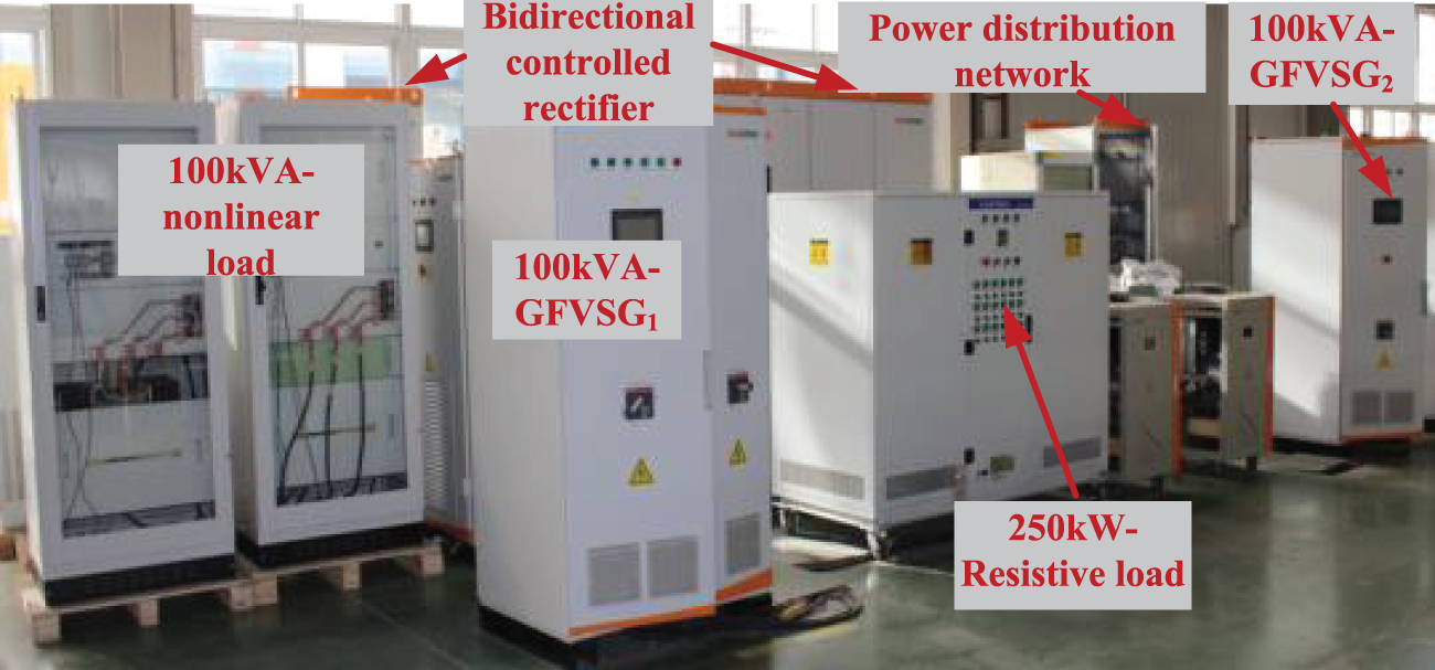
Figure 7: Energy storage microgrid system platform
During the experimental test, Pref = 20 kW, J = 6 kg·m2, D = 50.66, Kp = 1, Kd = 5.3 × 10⁻⁵ were set for 100kVA-GFVSG. Other main experimental parameters were consistent with Table 1 and the simulation parameters. Fig. 8a shows the experimental results under a power grid voltage step change of −1%. Fig. 8b shows the experimental outcomes for Qref transitioning from 0 to 30 kvar. As inferred from Eq. (2), the primary voltage regulation equation represents a first-order system. Regardless of whether the voltage step is −1% or the Qref steps from 0 to 30 kvar, the change in Qe remains non-oscillatory. Nevertheless, Fig. 8 demonstrates that the LLF-GFVSG can effectively suppress dynamic oscillations in active power caused by grid voltage and Qref disturbances. Consequently, this study focuses exclusively on the changes in the grid-connected active power Pe and output frequency f.
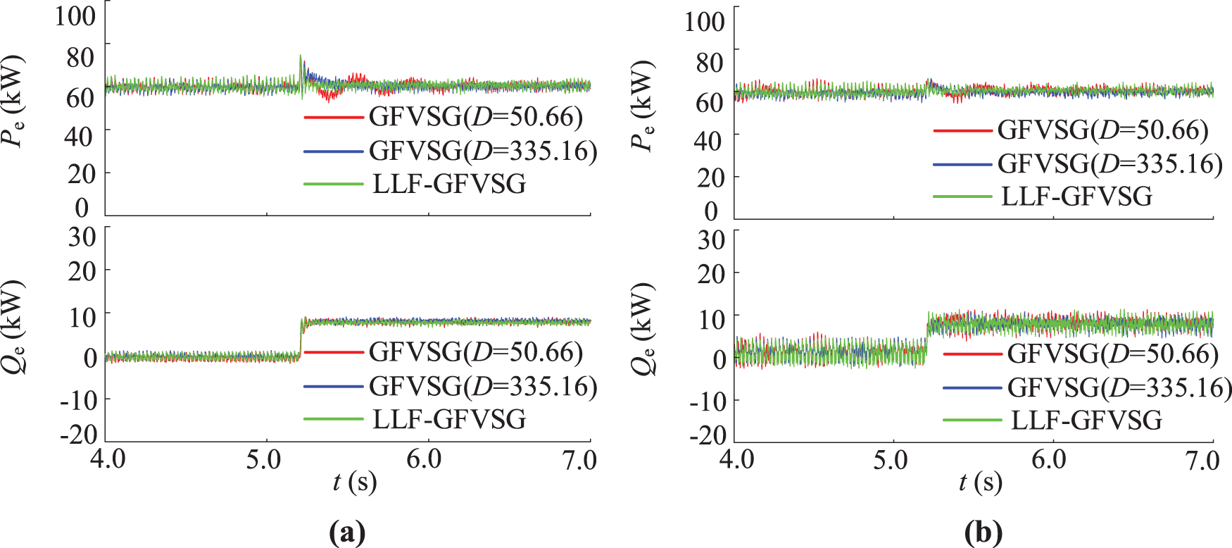
Figure 8: Comparative experimental results under (a) power grid voltage step −1% and (b) Qref step
Figs. 9a and 10a illustrate the experimental results for the Pe and f under the condition of X = 0.1 Ω, respectively. The comparison includes LLF-GFVSG, GFVSG (D = 50.66), and GFVSG (D = 335.16) during the transitions of Pref from 20 to 60 kW and fg from 50 to 49.95 Hz. Conversely, Figs. 9b and 10b illustrate the experimental results for the Pe and f under the condition of X = 0.05 Ω, respectively. The comparison includes LLF-GFVSG, GFVSG (D = 50.66), and GFVSG (D = 335.16) during the transitions of Pref from 20 to 60 kW and fg from 50 to 49.95 Hz.
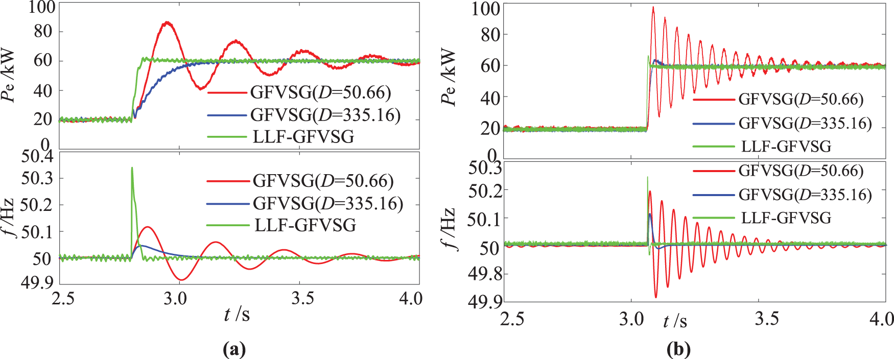
Figure 9: Comparative experimental results under Pref step. (a) X = 0.1 Ω. (b) X = 0.05 Ω
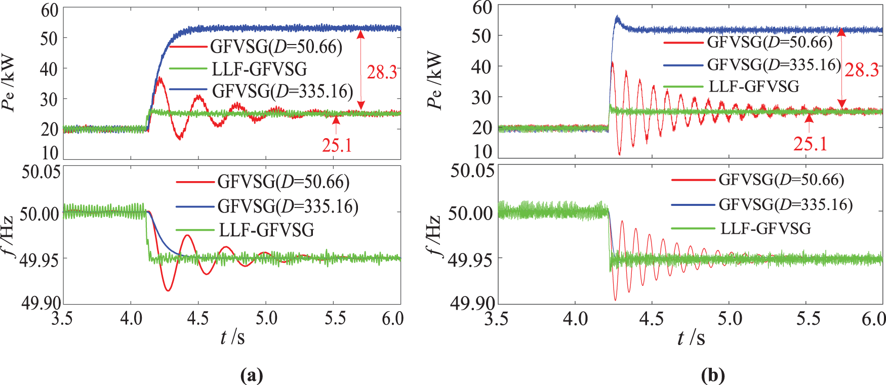
Figure 10: Comparative experimental results under fg step. (a) X = 0.1 Ω. (b) X = 0.05 Ω
According to the experimental comparison results shown in Figs. 9a and 10a, it is evident that the experimental outcomes during the transitions of Pref from 20 to 60 kW and fg from 50 to 49.95 Hz maintain a one-to-one correspondence with the simulation results presented in Fig. 5. According to the experimental comparison results shown in Figs. 9b and 10b, it is evident that the system’s damping ratio decreases as the line impedance decreases, resulting in more pronounced oscillations for GFVSG (D = 50.66). In contrast, the effectiveness and adaptability of LLF-GFVSG under the same conditions of reduced line impedance are markedly superior to those of GFVSG. Specifically, when the value of D increases from 50.66 to 335.16, the Pe and f for the GFVSG grid-connected system do not vibrate under the Pref and fg disturbances. However, the Pe has an active steady state deviation of ∆Pe0 = 28.3 kW at fg = 49.95 Hz, while the Pe and f of LLF-GFVSG do not have dynamic oscillation when responding to two disturbances of Pref and fg, and the Pe can eliminate the active steady state deviation at fg = 49.95 Hz. So ∆Pe01 is equal to 0.
In order to verify the effectiveness of LLF-GFVSG, we conducted parallel networking verification on the two GFVSGs shown in Fig. 7. The main system parameters for the parallel network system were configured as follows: Pref1 = 2Pref2 = 40 kW, D1 = 2D2 = 200, J1 = 2J2 = 6 kg·m2, Kd1 = 2Kd2 = 5.3 × 10⁻⁵, X1 = 2X2 = 0.1 Ω, kq1 = 2kq2 = 1.4 × 10⁻⁴. Fig. 11 shows the comparison of experimental results between LLF-GFVSG and traditional GFVSG during the running of two GFVSGs parallel networking. At the initial time, the GFVSG1 and GFVSG2 jointly support a 60 kW resistive load to maintain stable operation. The 60 kW resistive step load is applied at 1 s and removed at 1.6 s. As shown in Fig. 11a, the LLF-GFVSG parallel networking control method can effectively mitigate the dynamic oscillation of the output active power Pe in the parallel networking system under step disturbances of the system load, compared to the existing traditional GFVSG parallel networking control method. Similarly, as shown in Fig. 11b, the LLF-GFVSG parallel networking control method can also effectively address the dynamic oscillation of the output frequency fs in the parallel networking system under step disturbances of the system load, compared to the existing GFVSG parallel networking control method.
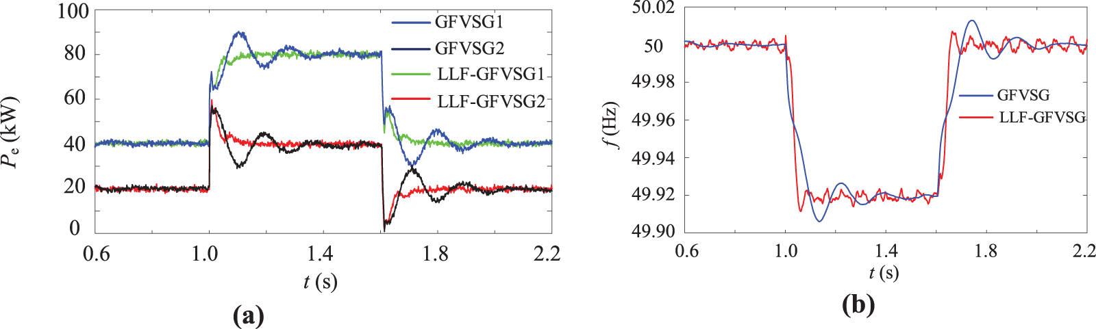
Figure 11: Comparative simulation results under load step. (a) Pe1 and Pe2. (b) fs
It is worth noting that because the proposed LLF-GFVSG directly employs ∆P for dynamic feed-forward compensation of ∆ω, the harmonic components present in Pe are introduced into f, resulting in the experimental test waveform of f containing more harmonics compared to that of the GFVSG. Consequently, the dynamic response waveform of f in the LLF-GFVSG exhibits a coarser envelope shape. Therefore, optimizing the dynamic response performance and waveform quality of the f of LLF-GFVSG when dealing with Pref and fg disturbances is one of the subsequent research works.
In order to solve the GCAP dynamic oscillation problem of GFVSG based on the first-order low-pass filter similar to that of TSG, an improved LLF-GFVSG control strategy is proposed. By means of theoretical analysis, mathematical modeling, parameter design, simulation, experimental comparison and verification, the following conclusions are derived:
(1) GFVSG can realize the dynamic oscillation suppression of Pe and f under the two disturbances of Pref and fg by increasing the value of D, but at the same time, increase the active steady state deviation of Pe under the condition that fg deviates from the rated value. In other words, the GFVSG has the problem that the GCAP dynamic response performance and its steady state performance cannot be balanced.
(2) The LLF-GFVSG can ensure that there are no dynamic oscillations in Pe and f under variations in parameters Ug, X, Qref, Pref, and fg, as well as in a parallel network system. Furthermore, the steady state deviation of Pe remains zero when fg deviates from its rated value, indicating that the LLF-GFVSG effectively resolves the challenge of balancing GCAP’s dynamic response performance with its steady-state performance, a limitation found in traditional GFVSG.
Acknowledgement: We sincerely appreciate the supported by the Key Laboratory of Modern Power System Simulation and Control & Renewable Energy Technology (Northeast Electric Power University) Open Fund of China throughout the manuscript preparation process.
Funding Statement: This work was supported by the Key Laboratory of Modern Power System Simulation and Control & Renewable Energy Technology (Northeast Electric Power University) Open Fund of China under Grant MPSS2024-08.
Author Contributions: The authors confirm their contribution to the paper as follows: study conception and design: Rongliang Shi, Lei Zhang; data collection: Lei Zhang; analysis and interpretation of results: Rongliang Shi, Junhui Li; logic and result verification: Yu Zhang; draft manuscript writing: Lei Zhang; manuscript check: Yannan Yu. All authors reviewed the results and approved the final version of the manuscript.
Availability of Data and Materials: The authors confirm that the data supporting the findings of this study are available within the article. The additional data that support the findings of this study are available on request from the corresponding author, upon reasonable request.
Ethics Approval: Not applicable.
Conflicts of Interest: The authors declare that they have no conflicts of interest to report regarding the present study.
References
1. W. Wang, X. Shi, G. Wu, and Y. Cao, “Interaction between grid-forming converters with AC grids and damping improvement based on loop shaping,” IEEE Trans. Power Syst., vol. 39, no. 1, pp. 1905–1917, Jan. 2024. doi: 10.1109/TPWRS.2023.3264591. [Google Scholar] [CrossRef]
2. A. Tayyebi, D. Groß, A. Anta, F. Kupzog, and F. Dörfler, “Frequency stability of synchronous machines and grid-forming power converters,” IEEE J. Emerg Sel. Top. Power Electron., vol. 8, no. 2, pp. 1004–1018, Jun. 2020. doi: 10.1109/JESTPE.2020.2966524. [Google Scholar] [CrossRef]
3. A. Asrari, M. Mustafa, M. Ansari, and J. Khazaei, “Impedance analysis of virtual synchronous generator-based vector controlled converters for weak AC grid integration,” IEEE Trans. Sustain. Energy, vol. 10, no. 3, pp. 1481–1490, Jul. 2019. doi: 10.1109/TSTE.2019.2892670. [Google Scholar] [CrossRef]
4. Z. Shuai, W. Huang, Z. J. Shen, A. Luo, and Z. Tian, “Active power oscillation and suppression techniques between two parallel synchronverters during load fluctuations,” IEEE Trans. Power Electron., vol. 35, no. 4, pp. 4127–4142, Apr. 2020. doi: 10.1109/TPEL.2019.2933628. [Google Scholar] [CrossRef]
5. T. Wen, D. Zhu, X. Zou, B. Jiang, L. Peng and Y. Kang, “Power coupling mechanism analysis and improved decoupling control for virtual synchronous generator,” IEEE Trans. Power Electron., vol. 36, no. 3, pp. 3028–3041, Mar. 2021. doi: 10.1109/TPEL.2020.3017254. [Google Scholar] [CrossRef]
6. H. Cheng, Z. Shuai, C. Shen, X. Liu, Z. Li and J. Shen, “Transient angle stability of paralleled synchronous and virtual synchronous generators in islanded microgrids,” IEEE Trans. Power Electron., vol. 35, no. 8, pp. 8751–8765, Aug. 2020. doi: 10.1109/TPEL.2020.2965152. [Google Scholar] [CrossRef]
7. C. Li, Y. Yang, N. Mijatovic, and T. Dragicevic, “Frequency stability assessment of grid-forming VSG in framework of MPME with feedforward decoupling control strategy,” IEEE Trans. Ind. Electron., vol. 69, no. 7, pp. 6903–6913, Jul. 2022. doi: 10.1109/TIE.2021.3099236. [Google Scholar] [CrossRef]
8. J. Liu, Y. Miura, H. Bevrani, and T. Ise, “A unified modeling method of virtual synchronous generator for multi-operation-mode analyses,” IEEE J. Emerg Sel. Top. Power Electron., vol. 9, no. 2, pp. 2394–2409, Apr. 2021. doi: 10.1109/JESTPE.2020.2970025. [Google Scholar] [CrossRef]
9. M. Chen, D. Zhou, and F. Blaabjerg, “Enhanced transient angle stability control of grid-forming converter based on virtual synchronous generator,” IEEE Trans. Ind. Electron., vol. 69, no. 9, pp. 9133–9144, Sep. 2022. doi: 10.1109/TIE.2021.3114723. [Google Scholar] [CrossRef]
10. W. Wu et al., “Sequence-impedance-based stability comparison between VSGs and traditional grid-connected inverters,” IEEE Trans. Power Electron., vol. 34, no. 1, pp. 46–52, Jan. 2019. doi: 10.1109/TPEL.2018.2841371. [Google Scholar] [CrossRef]
11. R. Shi, C. Lan, Z. Dong, and G. Yang, “An active power dynamic oscillation damping method for the grid-forming virtual synchronous generator based on energy reshaping mechanism,” Energies, vol. 16, no. 23, pp. 1–17, Nov. 2023. doi: 10.3390/en16237723. [Google Scholar] [CrossRef]
12. L. Huang, H. Xin, and Z. Wang, “Damping low-frequency oscillations through VSC-HVdc stations operated as virtual synchronous machines,” IEEE Trans. Power Electron., vol. 34, no. 6, pp. 5803–5818, Jun. 2019. doi: 10.1109/TPEL.2018.2866523. [Google Scholar] [CrossRef]
13. J. Alipoor, Y. Miura, and T. Ise, “Power system stabilization using virtual synchronous generator with alternating moment of inertia,” IEEE J. Emerg Sel. Top. Power Electron., vol. 3, no. 2, pp. 451–458, Jun. 2015. doi: 10.1109/JESTPE.2014.2362530. [Google Scholar] [CrossRef]
14. R. Shi, X. Zhang, C. Hu, H. Xu, J. Gu and W. Cao, “Self-tuning virtual synchronous generator control for improving frequency stability in autonomous photovoltaic-diesel microgrids,” J. Modern Power Syst. Clean Energy, vol. 6, no. 3, pp. 482–494, May 2018. doi: 10.1007/s40565-017-0347-3. [Google Scholar] [CrossRef]
15. V. Thomas, S. Kumaravel, and S. Ashok, “Fuzzy controller-based self-adaptive virtual synchronous machine for microgrid application,” IEEE Trans. Energy Conver., vol. 36, no. 3, pp. 2427–2437, Sep. 2021. doi: 10.1109/TEC.2021.3057487. [Google Scholar] [CrossRef]
16. M. Ren, T. Li, K. Shi, P. Xu, and Y. Sun, “Coordinated control strategy of virtual synchronous generator based on adaptive moment of inertia and virtual impedance,” IEEE J. Em. Sel. Top. C., vol. 11, no. 1, pp. 99–110, Mar. 2021. doi: 10.1109/JETCAS.2021.3051320. [Google Scholar] [CrossRef]
17. Y. Yang, C. Li, L. Cheng, X. Gao, J. Xu and F. Blaabjerg, “A generic power compensation control for grid forming virtual synchronous generator with damping correction loop,” IEEE Trans. Ind. Electron., vol. 71, no. 9, pp. 10908–10918, Sep. 2024. doi: 10.1109/TIE.2023.3342332. [Google Scholar] [CrossRef]
18. X. Xiong, C. Wu, P. Cheng, and F. Blaabjerg, “An optimal damping design of virtual synchronous generators for transient stability enhancement,” IEEE Trans. Power Electron., vol. 36, no. 10, pp. 11026–11030, Oct. 2021. doi: 10.1109/TPEL.2021.3074027. [Google Scholar] [CrossRef]
19. F. Mandrile, V. Mallemaci, E. Carpaneto, and R. Bojoi, “Lead-lag filter-based damping of virtual synchronous machines,” IEEE Trans. Ind. Appl., vol. 59, no. 6, pp. 6900–6913, Nov.–Dec. 2023. doi: 10.1109/TIA.2023.3293779. [Google Scholar] [CrossRef]
20. M. Yang, Y. Wang, S. Chen, X. Xiao, and Y. Li, “Comparative studies on damping control strategies for virtual synchronous generators,” IEEE Trans. Power Deliver, vol. 39, no. 2, pp. 859–873, Apr. 2024. doi: 10.1109/TPWRD.2023.3339288. [Google Scholar] [CrossRef]
21. H. Xu, C. Yu, C. Liu, Q. Wang, and X. Zhang, “An improved virtual inertia algorithm of virtual synchronous generator,” J. Modern Power Syst. Clean Energy, vol. 8, no. 2, pp. 377–386, Mar. 2020. doi: 10.35833/MPCE.2018.000472. [Google Scholar] [CrossRef]
22. X. Quan, A. Q. Huang, and H. Yu, “A novel order reduced synchronous power control for grid-forming inverters,” IEEE Trans Ind. Electron., vol. 67, no. 12, pp. 10989–10995, Dec. 2020. doi: 10.1109/TIE.2019.2959485. [Google Scholar] [CrossRef]
23. Y. Yu et al., “A reference-feedforward-based damping method for virtual synchronous generator control,” IEEE Trans. Power Electron., vol. 37, no. 7, pp. 7566–7571, Jul. 2022. doi: 10.1109/TPEL.2022.3152358. [Google Scholar] [CrossRef]
24. M. Li et al., “Phase feedforward damping control method for virtual synchronous generators,” IEEE Trans. Power Electron., vol. 37, no. 8, pp. 9790–9806, Aug. 2022. doi: 10.1109/TPEL.2022.3150950. [Google Scholar] [CrossRef]
25. R. Shi, C. Lan, J. Huang, and C. Ju, “Analysis and optimization strategy of active power dynamic response for VSG under a weak grid,” Energies, vol. 16, no. 12, pp. 1–18, Jun. 2023. doi: 10.3390/en16124593. [Google Scholar] [CrossRef]
26. P. Sun, J. Yao, Y. Zhao, X. Fang, and J. Cao, “Stability assessment and damping optimization control of multiple grid-connected virtual synchronous generators,” IEEE Trans. Energy Conver., vol. 36, no. 4, pp. 3555–3567, Dec. 2021. doi: 10.1109/TEC.2021.3104348. [Google Scholar] [CrossRef]
27. B. Long, X. Li, J. Rodríguez, J. Guerrero, and K. Chong, “Frequency stability enhancement of an islanded microgrid: A fractional-order virtual synchronous generator,” Int. J. Electr. Power Energy Syst., vol. 147, May 2023, Art. no. 108896. doi: 10.1016/j.ijepes.2022.108896. [Google Scholar] [CrossRef]
Cite This Article
 Copyright © 2024 The Author(s). Published by Tech Science Press.
This work is licensed under a Creative Commons Attribution 4.0 International License , which permits unrestricted use, distribution, and reproduction in any medium, provided the original work is properly cited.
 Downloads
 Citation Tools