
 Submit a Paper
 Propose a Special lssue
 Open Access
ARTICLE

A Novel Bi-Level VSC-DC Transmission Expansion Planning Method of VSC-DC for Power System Flexibility and Stability Enhancement
1 Support Center of Power System Technology, Central China Branch of State Grid Corporation of China, Wuhan, 430077, China
2 Hubei Engineering and Technology Research Center for AC/DC Intelligent Distribution Network, School of Electrical Engineering and Automation, Wuhan University, Wuhan, 430072, China
* Corresponding Author: Lei Chen. Email:
Energy Engineering 2024, 121(11), 3161-3179. https://doi.org/10.32604/ee.2024.054068
Received 17 May 2024; Accepted 24 July 2024; Issue published 21 October 2024
 View Full Text
 Download PDF
Abstract
Investigating flexibility and stability boosting transmission expansion planning (TEP) methods can increase the renewable energy (RE) consumption of the power systems. In this study, we propose a bi-level TEP method for voltage-source-converter-based direct current (VSC-DC), focusing on flexibility and stability enhancement. First, we established the TEP framework of VSC-DC, by introducing the evaluation indices to quantify the power system flexibility and stability. Subsequently, we propose a bi-level VSC-DC TEP model: the upper-level model acquires the optimal VSC-DC planning scheme by using the improved moth flame optimization (IMFO) algorithm, and the lower-level model evaluates the flexibility through time-series production simulation. Finally, we applied the proposed VSC-DC TEP method to the modified IEEE-24 and IEEE-39 test systems, and obtained the optimal VSC-DC planning schemes. The results verified that the proposed method can achieve excellent RE curtailment with high flexibility and stability. Furthermore, the well-designed IMFO algorithm outperformed the traditional particle swarm optimization (PSO) and moth flame optimization (MFO) algorithms, confirming the effectiveness of the proposed approach.Keywords
Nomenclature
| Upward flexibility demands for node j at time t | |
| Downward flexibility demands for node j at time t | |
| Maximum and minimum RE output power at node j | |
| Upward flexibility carrier capacity for transmission line i | |
| Downward flexibility carrier capacity for transmission line i | |
| Transfer power margin of transmission line i at time t | |
| Maximum allowable power of transmission line i at time t | |
| Pi,line(t) | Transfer power of transmission line i at time t |
| Upward flexibility demands for transmission line i | |
| Downward flexibility demands for transmission line i | |
| Nb, NVSC | Number of nodes and number of VSC-DC access nodes |
| ηins | Total IFR of transmission lines |
| Upward and downward IFRs | |
| Average IFR of the overall power system | |
| Mi | HMESCR of node i |
| Sac,i | Short circuit capacity of node i |
| PVSC(i) | Capacity of the VSC-DC to be installed at node i |
| QVSC(j) | Reactive power controllable range of the VSC-DC at node j |
| MIIFj,i | Multi-infeed interaction factor between nodes j and i |
| Zeqj,i | Thevenin equivalent mutual-impedance between nodes i and j |
| Zeqi,i | Thevenin equivalent self-impedance of node i |
| Bj,i | Mutual-susceptance between nodes i and j |
| Bj,j | Self-susceptance of node i |
| Z1, Z2 | Objective functions of the upper- and lower-level model |
| z1, z2, z3 | Sub-objective functions |
| LVSC | Actual number of transmission lines for planning |
| Maximum number of transmission lines for planning | |
| Coper | Total operation cost |
| CG | Operation cost of the conventional generator |
| CRE, CLOAD | RE curtailment and load shedding penalty cost |
| Pg(t) | Output power of conventional generator g at time t |
| ag, bg, cg | Generation cost coefficients of conventional generator g |
| cRE, cLOAD | Penalty cost factors for RE curtailment and load shedding |
| WRE,i, WLOAD,i | Total energies of RE curtailment and load shedding |
| PRE,i, PLOAD,i | Active powers of RE, and load at node i |
| QRE,i, QLOAD,i | Reactive powers of RE, and load at node i |
| δ | Maximum ramp rate of the conventional generator i |
| PLine,i | Active power at transmission i |
| Ui | Voltage magnitude of node i |
| NM, NF | Numbers of moth and flame populations |
| dim | Dimension of the search space |
| it, maxit | Number of iterations and maximum number of iterations |
| r | Convergence speed coefficient |
| Maximum values of the initially generated moth population | |
| Minimum values of the initially generated moth population |
Power system transmission expansion planning (TEP) is an optimization problem aimed at expanding the existing transmission network by determining the optimal location and capacity of the transmission lines to match the growing power demands and ensure stable operation [1–3]. The voltage-source-converter-based direct current (VSC-DC) transmission exhibits great potential in TEP due to its flexibility and excellent control capabilities. It is considered a promising way to achieve carbon peaking and carbon neutrality goals by promoting renewable energy (RE) consumption [4]. However, new challenges emerge with the increasing participation of RE and DC transmission in VSC-DC TEP.
Due to the inherent uncertainty of RE, short-term flexible operational characteristics of the power system should be considered in VSC-DC TEP [5,6]. Tejada-Arango et al. [7] and Dai et al. [8] presented the power-based generation expansion planning model with an emphasis on the importance of appropriately modeling flexibility. They showed that the power-based model can represent flexibility capabilities accurately and lead to more cost-effective planning. In contrast, if flexibility is incorrectly modeled or ignored, it may lead to overly optimistic planning. Chen et al. [9] proposed a joint generation and transmission expansion planning method that leveraged the flexibility of generation sources, and as a result, achieved superior RE consumption capacity. While the abovementioned studies offer some helpful techniques for incorporating flexibility into planning problems, they only consider the flexibility of generation and neglect that of line delivery, which is equally critical to promoting RE consumption.
On the other hand, it is also necessary to incorporate the impact of VSC-DC integration on power system stability into TEP, otherwise, the power system may suffer from serious faults under inappropriate access to VSC-DC. Myasse et al. [10,11] conducted a more detailed analysis of the VSC-DC control performance and fault ride-through ability. In this article, the static voltage stability is given special consideration. A widely verified method to investigate static voltage stability of a DC-based power system is the application of the short-circuit ratio (SCR) index to evaluate the voltage strength: a power system with a low SCR tends to be unstable when facing disturbances and faults [12,13]. Jin et al. [14] designed the node-system SCR (NSCR) to plan the location and accommodation capacity of RE by evaluating the static voltage stability. Similarly, Yuan et al. [15] adopted the generalized SCR (gSCR) to assess the maximal capacity of grid-following converters and demonstrated its suitability for VSC-DC planning. However, the studies in [14,15] on static voltage stability are not comprehensive because the SCR indices fail to consider the influence of reactive power. Therefore, Kim et al. [16] developed the hybrid multi-infeed effective SCR (HMESCR) for the hybrid multi-infeed high voltage direct current (HVDC) systems with VSC-HVDC. Through steady and dynamic state simulations, they proved the applicability of HMESCR in determining the static voltage stability of VSC-DC-based power systems. In a sense, the SCR-based indices have demonstrated promising applicability for static voltage stability problems. However, these studies modeled the indices only as stability constraints, which may not fully exploit the static voltage stability. However, considering the SCR-based indices as optimization targets in VSC-DC TEP is expected to further boost the static voltage stability, which would be more favorable to the power system.
Aiming at the preceding problems, in this study, we put forward a bi-level planning method to expand VSC-DC on the existing power corridors, with a goal to improve the RE curtailment by enhancing line delivery flexibility and static voltage stability of the power system. The main contributions of this study are summarized as follows:
(1) We developed a TEP framework for VSC-DC from the perspectives of flexibility and stability, with a particular focus on line delivery flexibility.
(2) We established a bi-level VSC-DC TEP model and designed an improved moth flame optimization (IMFO) algorithm for the model-solving problem.
(3) We validated the effectiveness of the proposed bi-level TEP method of VSC-DC through case studies and verified the performance of IMFO algorithm compared to the traditional particle swarm optimization (PSO) and moth flame optimization (MFO) algorithms.
The remaining sections of this article are organized as follows: Section 2 establishes the proposed VSC-DC TEP framework, expounding the definitions and formulations of the flexibility and stability indices; Section 3 describes the bi-level TEP model of VSC-DC, defines the objective function and constraints of each level, and demonstrates the IMFO-based solution; Section 4 goes through the verification case studies based on the IEEE-24 and IEEE-39 test systems. The results are discussed in Section 5, and finally, the conclusions and future work directions are provided in Section 6.
The proposed VSC-DC TEP framework is dedicated to improving the RE curtailment by enhancing the flexibility and stability of the power system. Firstly, the TEP requires flexibility to deal with the uncertainty caused by the integration of massive RE. Therefore, within the presented framework, VSC-DC should be appropriately planned to provide flexibility, allowing smoother power delivery for RE. For this purpose, we define the flexibility carrier capacity (FCC) and insufficient flexibility ratio (IFR) indices. Furthermore, the stability mentioned in the framework refers to the power system static voltage stability, which may deteriorate if faced with inappropriate access to VSC-DC [17]. Therefore, we also define the HMESCR index to quantify the impact of VSC-DC integration on stability.
2.1 VSC-DC TEP Flexibility Index
First, let us take a brief look at the flexibility demand and supply process of the power system. The flexibility demand of the power system mainly arises from unexpected power fluctuations of the RE sources, while its flexibility supply is primarily provided by the peak regulation margin of controllable units (e.g., thermal units) [18]. For example, when there is a sudden drop in the RE output power, the thermal units are expected to adjust output power upward to achieve power balance, meeting the flexibility demand. Hence, the flexibility demand of RE sources can be modeled as
Note that the flexibility demand will only be met if the system can provide sufficient flexibility resources and line delivery flexibility. In this study, we particularly focused on the line delivery flexibility, quantified by the FCC index expressed as [19]
where
In order to calculate the flexibility demand for transmission lines, we introduce the power transmission distribution factor (PTDF), hij, between transmission line i and node j as
The FCC index in Eq. (2) evaluates the transmission line flexibility: if the FCC index is < (>) 0, the power system has sufficient (insufficient) line delivery flexibility. However, it is worth noting that adequate line delivery flexibility does not necessarily satisfy the system flexibility demands as it also depends on the availability of sufficient flexibility supply resources. Nonetheless, the proposed TEP framework is only concerned with line delivery flexibility. Besides, the FCC index will improve as the VSC-DC installation capacity increases, which will essentially boost the maximum allowable power of the lines under the same transmission corridor.
To measure the lack of flexibility of transmission lines, we define the IFR and average IFR (AIFR) indices as
2.2 VSC-DC TEP Stability Index
The HMESCR index in Eq. (5) is designed to reflect the impact of VSC-DC access on the static voltage stability of the DC access node. The multi-infeed interaction factor (MIIF) is embedded in the HMESCR to highlight the interactions between multiple DCs as [20]
where MIIFj,i can be expressed as
The larger the Mi value, the stronger the static voltage stability of node i. More specifically, when the value of Mi is less than the threshold (set as 3 according to [16]), node i cannot serve as a candidate node for VSC-DC planning due to insufficient stability. It can also be inferred from Eq. (5) that as the capacity of installed VSC-DC increases, the HMESCR index becomes progressively worse, reflecting the increasing impact of VSC-DC on stability.
Since the traditional HMESCR index cannot correctly evaluate the static voltage stability of the overall power system, which may jeopardize its application in VSC-DC TEP, we adopt an HMESCR-derived index to evaluate the general static voltage stability, expressed as
Note that the reactive power term of HMESCR enables VSC-DC to boost the static voltage stability, whereas the line-commutated converter DC (LCC-DC) does not possess this capability.
3 Bi-Level TEP Model of VSC-DC
In this section, we establish a bi-level TEP model for VSC-DC based on the indices presented, as displayed in Fig. 1. First, the objective functions and constraints of the upper- and lower-level models are carefully designed. Then, the exchanged variables between the two models are expatiated. Additionally, we present the solving method for the upper-level model.
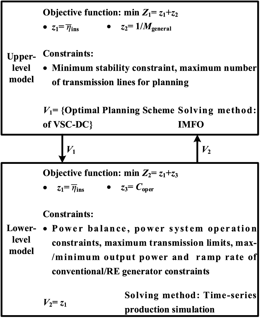
Figure 1: Framework of the proposed bi-level TEP model for VSC-DC
The upper-level optimization model aims to acquire the optimal VSC-DC planning scheme from the perspectives of flexibility and stability. Hence, the objective function for the upper-level model can be expressed as
The constraints are guaranteed by the minimum required stability constraint as Eq. (9) and the maximum number of transmission lines for planning as Eq. (10).
The variable exchanged from the upper- to the lower-level model, M1, can be defined as the optimal VSC-DC planning scheme. The upper-level model adopted a novel optimization algorithm, i.e., the IMFO, whose principle will be described in Section 3.3.
The lower-level model aims to calculate the flexibility index by conducting time-series production simulation, where the optimal power flow (OPF) is applied for the VSC-DC system [21]. The objective function of the OPF involves flexibility and operation costs, Coper, which can be modeled as
The constraints of the lower-level model include power balance, Eq. (15), maximum/minimum output power of conventional/RE generator, Eq. (16), ramp rate of the conventional generator, Eq. (17), maximum transmission limit, Eq. (18), and node voltage limit, Eq. (19), expressed as
Based on the objective function and constraints mentioned above, the lower-level model conducts time-series production simulations to obtain the flexibility index, which is also defined as the exchanged variable M2 to the upper-level model.
3.3 Model-Solving Method Based on IMFO
To solve the proposed bi-level VSC-DC TEP model, we meticulously improve a population intelligence optimization algorithm. Note that optimization based on convex relaxation, such as the second-order cone (SOC), can also be considered in TEP. However, we chose not to employ convex optimization methods due to the following reasons: (i) Reformulating the proposed VSC-DC TEP based on the highly strict requirements on the standard form of the SOC method would be too complicated; and (ii) the SOC method is less computationally efficient when applied to large-scale power systems, which may jeopardize the ability to solve the problem to global optimality [22]. Therefore, this paper adopts the IMFO algorithm, and the theory is demonstrated below: Firstly, the principle of the traditional MFO algorithm is explained. Secondly, the IMFO algorithm, which is applied to solve the upper-level model, is carefully designed. Finally, the upper-level model-solving process based on the IMFO algorithm is elaborated.
The traditional MFO algorithm achieves optimization by imitating the behavior of moths tracking flames [23]. Here, the moths and flames represent candidate solutions and the latest optimal solutions, respectively, and can be described as
where the ith moth can be expressed as Xmoth,i = [Xmoth,i,1, Xmoth,i,2,..., Xmoth,i,dim], where dim represents the dimension of the search space. Similarly, the ith flame can be expressed as Xflame,i = [Xflame,i,1, Xflame,i,2,..., Xflame,i,dim].
The iteration of the moth population can be expressed as
where t ∈ [r, 1] is the convergence path coefficient; the convergence speed coefficient, r, can be defined as
which decreases linearly from –1 to –2 over the iterations.
After updating the moth, the flame is appointed based on the optimal moths. The first flame represents the optimal solution in the contemporary iteration. To ensure global optimization, the number of flames decreases as
where round (·) represents the rounding-off function.
Although the traditional MFO exhibits excellent optimization capabilities, there remains room for improvement: (i) MFO generates initial solutions randomly within the feasible region, which may cause the initial solution to fall into a local optimum, resulting in premature phenomena; and (ii) the decrease in the number of flames, in Eq. (23) will inevitably cause a loss in population diversity, which is harmful to the optimization procedure.
To deal with the first issue, we adopted an initialization method based on logistic chaotic mapping [24,25], defined as
For the second issue, we defined a new iteration formula for the number of flames as
For it = maxit, the NF value in Eq. (23) reduces to 1, while it drops only to NM/2 in Eq. (25).
The process of the IMFO algorithm is summarized as follows (Fig. 2): First, we initialize the moth population based on chaotic mapping and appoint the top NF moths to the flame population. Subsequently, we update the moth and flame populations according to the new iteration equations. Finally, the optimal solution is obtained when the stopping criterion is met.
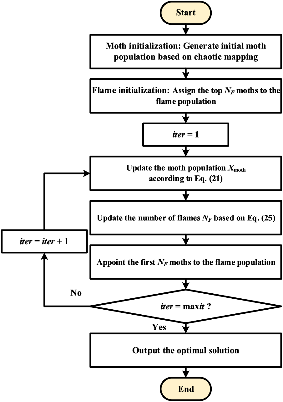
Figure 2: Flow of the proposed IMFO algorithm
The model-solving method based on the IMFO involves the following steps (Fig. 3): First, we acquire solutions, i.e., VSC-DC planning schemes, by using the IMFO algorithm. Then, we obtain the sub-functions z1, z2, and z3 from the bi-level VSC-DC TEP model and calculate the objective function Z1 of the VSC-DC planning scheme. Finally, if the algorithm meets the termination criterion, optimal solutions are obtained.
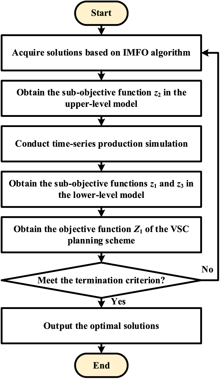
Figure 3: Flow of IMFO-based model-solving method
To verify the effectiveness of the proposed VSC-DC TEP in promoting power system flexibility and stability, we conducted case studies on the modified IEEE-24 and IEEE-39 test systems using MATLAB 2022a on a PC with Intel Core i7-12700 CPU @2.10 GHz and 16 G memory. For comparison with the existing methods, we set up three test cases:
(1) Case 1: Without VSC-DC TEP.
(2) Case 2: VSC-DC TEP considering only flexibility enhancement.
(3) Case 3: Proposed VSC-DC TEP considering both flexibility and stability enhancements.
Note that this study proposes a VSC-DC TEP dedicated to achieving better RE curtailment, essentially boosting line delivery flexibility, while ensuring the static voltage stability. Most existing methods based on flexibility do not consider static voltage stability improvements, which may cause instabilities. Therefore, Case 2 could be recognized as the existing method.
4.1 Case Study on the Modified IEEE-24 Test System
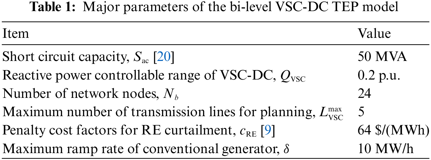
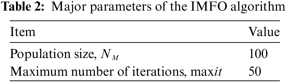
The modified IEEE-24 test system, as depicted in Fig. 4, consists of 34 transmission corridors and 10 power plants, including thermal synchronous generators, wind power at Bus 1 and Bus 2, and photovoltaic power at Bus 18 and Bus 21. To exert pressure on transmission lines, the load capacity was increased by 150% [26]. The major parameters of the bi-level VSC-DC TEP model and the IMFO algorithm are listed in Tables 1 and 2, respectively. Table 3 shows the VSC-DC planning scheme under different cases, including the locations and capacities of VSC-DC along with the flexibility and stability indices of each planning scheme. Besides, the red dashed lines in Fig. 4 are the planned VSC-DC.
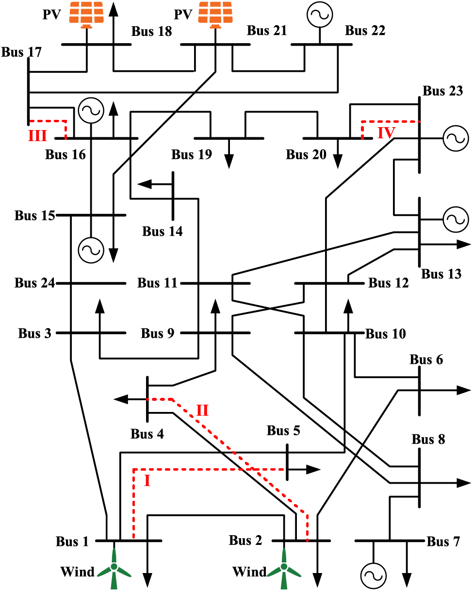
Figure 4: Topology of the modified IEEE-24 test system
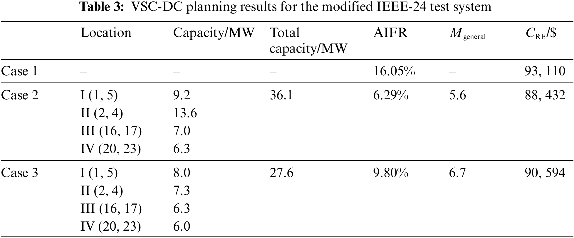
Focusing on the line delivery flexibility, the AIFR of Case 1 was 16.05% (Table 3), suggesting that the test system possessed insufficient flexibility and required VSC-DC planning. For Case 2, the AIFR improved from 16.05% to 6.29%. Whereas, for Case 3 with all included considerations, the AIFR reached 9.80%. We further studied the development trend of line delivery flexibility using the representative transmission lines (1, 5), (2, 4), (16, 17), and (20, 23), as depicted in Fig. 5.
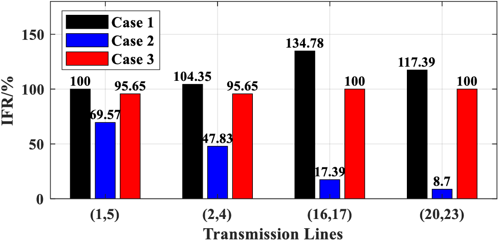
Figure 5: IFR under different cases for the modified IEEE-24 test system
All representative transmission lines suffered a severe lack of flexibility in Case 1 (ηins > 100%; Fig. 5). For Case 2, the ηins of the transmission lines (1, 5), (2, 4), (16, 17), and (20, 23) decreased by 30.43%, 54.16%, 87.1%, and 92.59%, respectively, compared to Case 1, whereas, for Case 3, they decreased respectively by 4.35%, 8.34%, 25.81%, and 14.81%, compared to Case 1, i.e., relatively lower than those under Case 2. From these results, we can infer that the planning of VSC-DC helps improve line delivery flexibility, as the IFRs in Cases 2 and 3 show a decreasing trend compared to Case 1. However, the induced effect of VSC-DC TEP on improving the line delivery flexibility is mainly related to the total capacity of VSC-DC, which explains the larger IFRs in Case 3 compared to Case 2.
Further, we analyzed the CRE values for Cases 1, 2, and 3 (Table 3). Although the CRE in Case 3 was larger than that in Case 2, they were both smaller than that in Case 1. Although the proposed method did not directly regard RE curtailment as the optimization objective, the ability to alleviate it was favorably improved. This validated the effectiveness of the proposed method in promoting RE consumption.
To analyze the static voltage stability, we computed the HMESCR of VSC-DC access nodes (Fig. 6). For Case 2, the HMESCR of nodes 1 and 2 were lower than the threshold value (Mi = 3). This indicated an excessive access of VSC-DC in Case 2, resulting in lower stability, which may cause security and stability issues. In Case 3, the HMESCR of all nodes was larger than that of Case 2, and well within the constraint margin. Particularly, the Mgeneral value for Case 3 (6.7) was larger than that of Case 2 (5.6). This indicated that the proposed VSC-DC TEP method in Case 3 not only enabled flexibility improvements, but also ensured better stability. Although Case 2 was better at boosting flexibility, the stability was favorably improved in Case 3. Therefore, the efficacy of the proposed method in balancing flexibility and stability was affirmed.
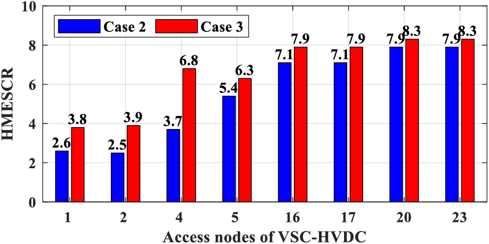
Figure 6: HMESCR under Cases 2 and 3 for the modified IEEE-24 test system
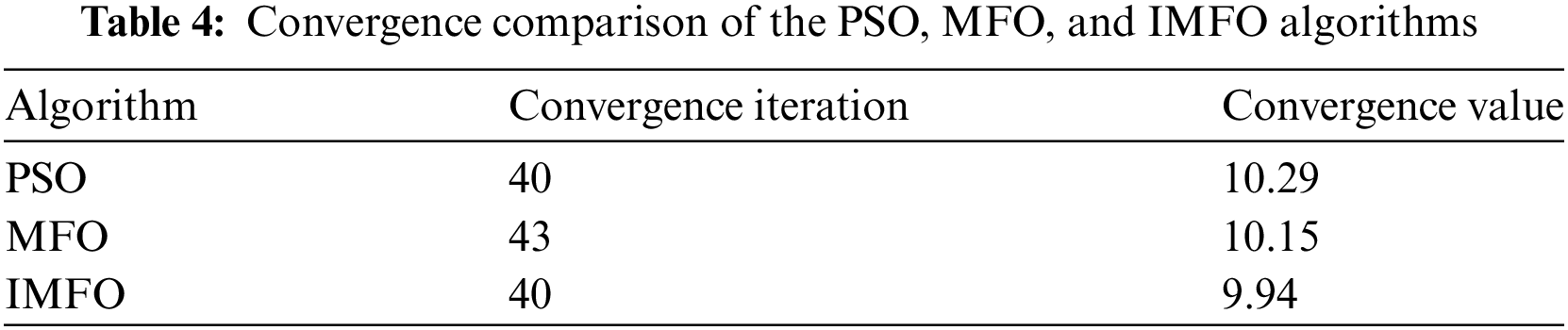
Furthermore, to validate its convergence superiority, the proposed IMFO algorithm was compared with the MFO and PSO algorithms (PSO parameters can be referred from [27]). For the objective function Z1 in Eq. (8), the convergence curves for the different algorithms were computed (Fig. 7; Table 4). These results revealed that IMFO exhibited the best convergence iteration and value among the three algorithms. Generally speaking, the IMFO algorithm outperformed the MFO and PSO algorithms.
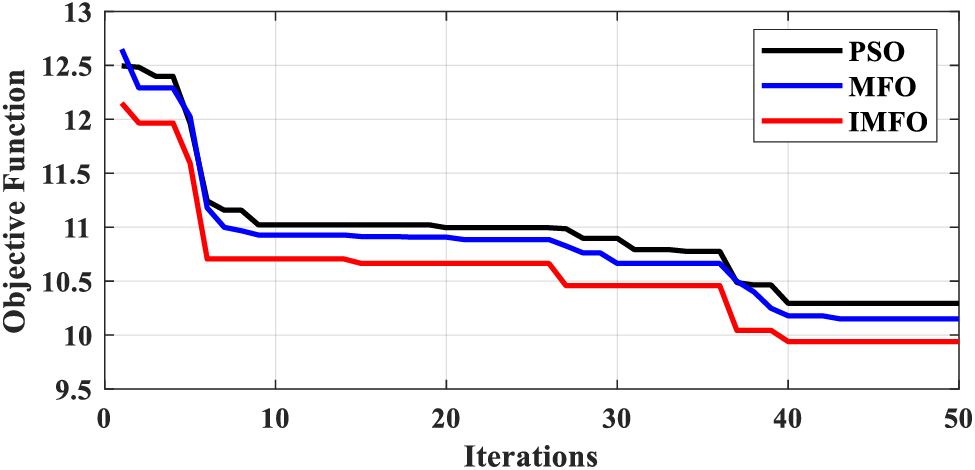
Figure 7: Convergence curves of the PSO, MFO, and IMFO algorithms
4.2 Case Study on the Modified IEEE-39 Test System
To test the effectiveness and suitability of the proposed VSC-DC TEP method for more complex power systems, we built a modified IEEE-39 test system on MATLAB, as shown in Fig. 8, with wind power at Bus 30 and Bus 37, and photovoltaic power at Bus 33 and Bus 35. To put pressure on the transmission lines, the load capacity was increased by 200% and the line delivery capacity was decreased by 30%.
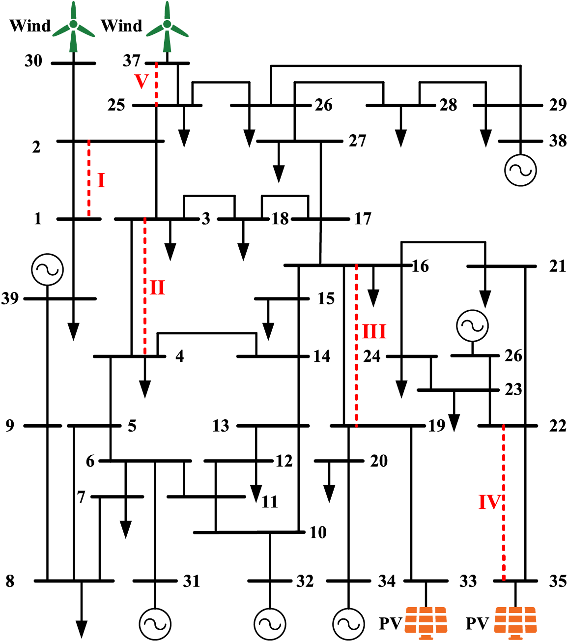
Figure 8: Topology of the modified IEEE-39 test system
Analogously, we computed the planning results under Cases 1, 2, and 3 for the IEEE-39 system, including flexibility and stability indices as well as the RE curtailment penalty cost (Table 5). The AIFR of Case 3 was slightly larger than that of Case 2, but 20.28% lower than that of Case 1.
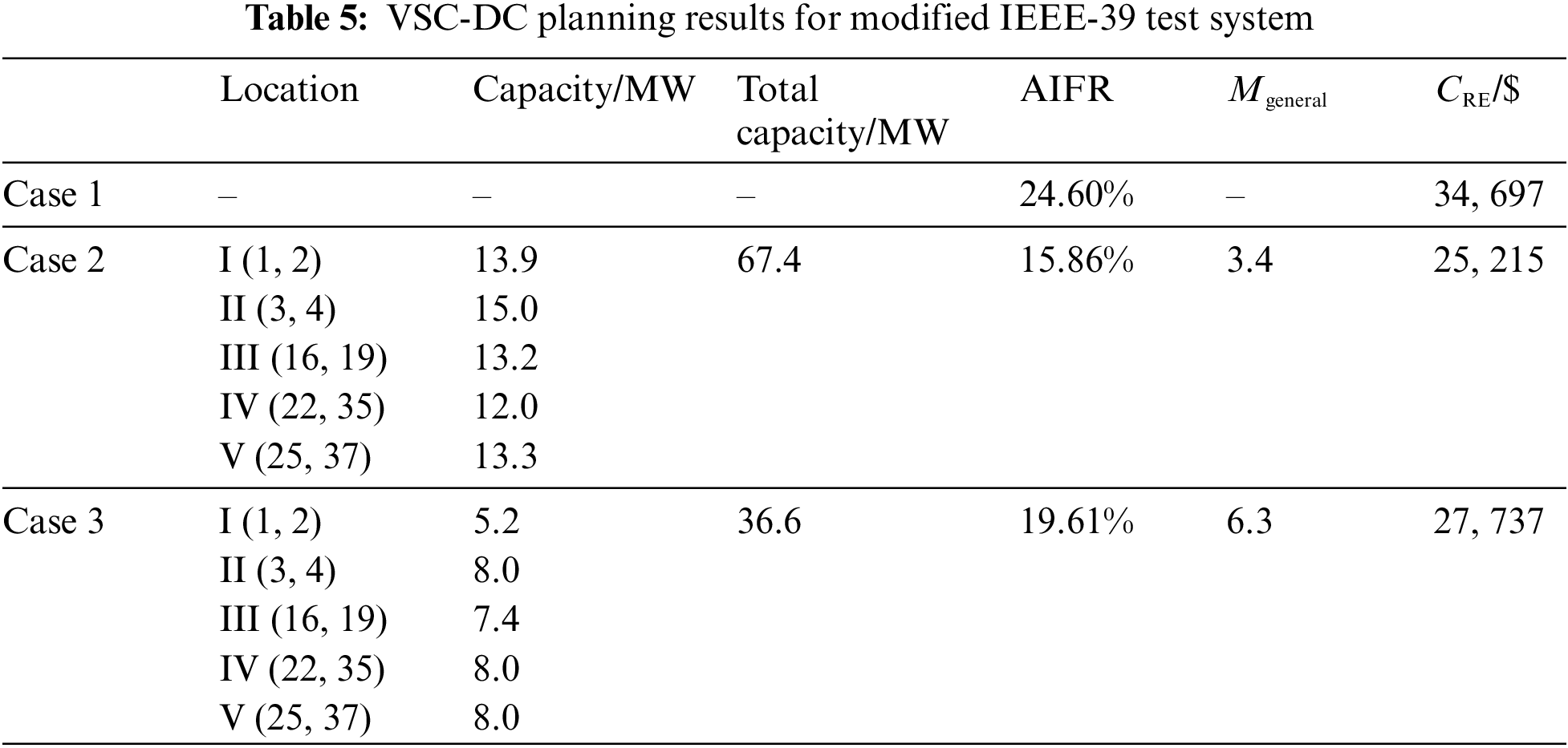
Choosing representative transmission lines (1, 2), (3, 4), (16, 19), (22, 35), and (25, 37), the IFRs under the three cases were computed (Fig. 9). A similar development trend was observed for this parameter as well: the IFRs of Case 3 were slightly larger than those in Case 2, but still better than those in Case 1.

Figure 9: IFR under different cases for the modified IEEE-39 test system
Furthermore, the CRE of Cases 2 and 3 were 27.33% and 20.06% smaller than that of Case 1 (Table 5), emphasizing the effects of VSC-DC planning on improving the RE curtailment.
As for the static voltage stability, the HMESCR of nodes 2 and 25 for Case 2 went beyond the threshold (Fig. 10). For Case 3, the HMESCR values of all nodes were within the limit, while being larger than those of Case 2, showing better static voltage stability. Therefore, the proposed method exhibited favorable performance in improving flexibility and stability, thereby ensuring better RE curtailment. In general, the suitability of the proposed VSC-DC TEP method for the modified IEEE-39 system revealed that it can be applied to complex power systems.
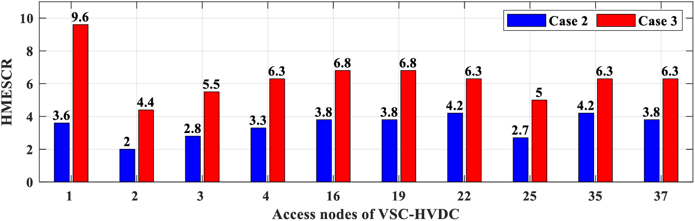
Figure 10: HMESCR under Cases 2 and 3 for the modified IEEE-39 test system
The major findings of this study are summarized as follows:
(1) The proposed VSC-DC TEP method decreases the AIFR by 38.94% and 20.28% in the modified IEEE-24 and IEEE-39 systems, respectively. While considering only flexibility in VSC-DC TEP, the planning results suggest that the static voltage stability may exceed the limit. Note that the flexibility boosting function of the proposed approach in the IEEE-39 system is weaker than that in the IEEE-24 system, which may be potentially related to the increase in the flexibility demand of the power system. We plan to further investigate this in follow-up works.
(2) Judging from the CRE development trend in the modified IEEE-24 and IEEE-39 test systems, the proposed method seems to exhibit the ability to improve RE curtailment. This is achieved through reasonable planning of VSC-DC, essentially enhancing the line delivery flexibility while ensuring the static voltage stability of the power system. Although the proposed approach does not directly treat it as the optimization objective, it well alleviates RE curtailment.
(3) The proposed IMFO algorithm shows better convergence speed and accuracy than the MFO and PSO algorithms for the VSC-DC TEP. Specifically, the IMFO, MFO, and PSO algorithms converged at the 40th, 43rd, and 40th iterations, with fitness values of 9.94, 10.15, and 10.29. Compared to PSO, MFO has better optimization capabilities because of the spiral optimization path of the moth [23]. However, MFO converges slower than the PSO, which is addressed by introducing the logistic chaotic mapping to construct the IMFO. As a result, the IMFO outperforms MFO and PSO in the first iteration and eventually exhibits the best convergence speed and fitness value.
In this study, we propose a bi-level TEP of VSC-DC to improve the RE curtailment by enhancing the flexibility and stability of the power system. We selected appropriate evaluation indices from the perspective of flexibility and static voltage stability to serve as the optimization target of the VSC-DC TEP. The IMFO algorithm was developed to solve the proposed VSC-DC TEP model efficiently. Case studies conducted on the IEEE-24 and IEEE-39 systems verified the advancement and effectiveness of the proposed method. The results show that the proposed VSC-DC TEP method can comprehensively enhance the flexibility and stability of the power system, thereby improving the RE curtailment.
This primary shortcoming of the proposed bi-level TEP method is that it can be used only for VSC-DC planning and does not include LCC-DC planning. Nonetheless, the present method can serve as a guideline for VSC-DC planning and is expected to contribute to RE consumption. In the future, we plan to expand the proposed method for LCC-DC planning and apply it to a real power system with multi-region alternating and direct current interconnection to test its RE consumption boosting effect. The research findings will be reported in the latest articles.
Acknowledgement: The authors acknowledge the support of the Central China Branch of State Grid Corporation of China.
Funding Statement: This work was supported by the Science and Technology Project of Central China Branch of State Grid Corporation of China under Grant 52140023000T.
Author Contributions: The authors confirm their contribution to the paper as follows: The study conception and design: Weigang Jin, Lei Chen, and Shencong Zheng. Data collection: Weigang Jin, Lei Chen, and Shencong Zheng. Analysis and interpretation of results: Lei Chen, Shencong Zheng, Yuqi Jiang, Yifei Li, and Hongkun Chen. Draft manuscript preparation: Weigang Jin, Lei Chen, Yuqi Jiang, and Hongkun Chen. All authors reviewed the results and approved the final version of the manuscript.
Availability of Data and Materials: Data supporting this study are included within the article.
Ethics Approval: Not applicable.
Conflicts of Interest: The authors declare that they have no conflicts of interest to report regarding the present study.
References
1. Á. García-Cerezo, R. García-Bertrand, and L. Baringo, “Priority chronological time-period clustering for generation and transmission expansion planning problems with long-term dynamics,” IEEE Trans. Power Syst., vol. 37, no. 6, pp. 4325–4339, Nov. 2022. doi: 10.1109/TPWRS.2022.3151062. [Google Scholar] [CrossRef]
2. Y. Chen, Z. Song, and Y. Hou, “Climate-adaptive transmission network expansion planning considering evolutions of resources,” IEEE Trans. Ind. Inf., vol. 20, no. 2, pp. 2063–2078, Feb. 2024. doi: 10.1109/TII.2023.3284012. [Google Scholar] [CrossRef]
3. N. Y. Puvvada, A. Mohapatra, and S. C. Srivastava, “Robust AC transmission expansion planning using a novel dual-based bi-level approach,” IEEE Trans. Power Syst., vol. 37, no. 4, pp. 2881–2893, Jul. 2022. doi: 10.1109/TPWRS.2021.3125719. [Google Scholar] [CrossRef]
4. H. Fang et al., “Analysis of additional damping control strategy and parameter optimization for improving small signal stability of VSC-HVDC system,” Energy Eng., vol. 120, no. 4, pp. 931–948, Sep. 2022. doi: 10.32604/ee.2023.025163. [Google Scholar] [CrossRef]
5. M. B. Hadi, M. Moeini-Aghtaie, M. Khoshjahan, and P. Dehghanian, “A comprehensive review on power system flexibility: Concept, services, and products,” IEEE Access, vol. 10, pp. 99257–99267, Sep. 2022. doi: 10.1109/ACCESS.2022.3206428. [Google Scholar] [CrossRef]
6. T. Heggarty, J. Y. Bourmaud, R. Girard, and G. Kariniotakis, “Quantifying power system flexibility provision,” Appl. Energy, vol. 279, pp. 115852, Dec. 2020. doi: 10.1016/j.apenergy.2020.115852. [Google Scholar] [CrossRef]
7. D. A. Tejada-Arango, G. Morales-España, S. Wogrin, and E. Centeno, “Power-based generation expansion planning for flexibility requirements,” IEEE Trans. Power Syst., vol. 35, no. 3, pp. 2012–2023, May 2020. doi: 10.1109/TPWRS.2019.2940286. [Google Scholar] [CrossRef]
8. W. Dai et al., “Incorporating external flexibility in generation expansion planning,” IEEE Trans. Power Syst., vol. 36, no. 6, pp. 5959–5962, Nov. 2021. doi: 10.1109/TPWRS.2021.3101700. [Google Scholar] [CrossRef]
9. Z. Chen, Y. Hu, N. Tai, X. Tang, and L. Li, “Source-grid joint planning of renewable energy power system considering flexibility and economy,” (in Chinese), Electr Power Autom. Equip., vol. 42, no. 9, pp. 94–101, Sept. 2022. doi: 10.16081/j.epae.202204021. [Google Scholar] [CrossRef]
10. I. E. Myasse et al., “Improvement of real-time state estimation performance in HVDC systems using an adaptive nonlinear observer,” IFAC J. Syst. Control, vol. 27, pp. 100244, Mar. 2024. doi: 10.1016/j.ifacsc.2024.100244. [Google Scholar] [CrossRef]
11. I. E. Myasse et al., “Observer and nonlinear control design of VSC-HVDC transmission system,” Int. J. Electr. Power Energy Syst., vol. 145, pp. 108609, Feb. 2023. doi: 10.1016/j.ijepes.2022.108609. [Google Scholar] [CrossRef]
12. G. Wang, H. Xin, D. Wu, Z. Li, and P. Ju, “Grid strength assessment for inhomogeneous multi-infeed HVDC systems via generalized short circuit ratio,” J. Mod. Power Syst. Clean Energy, vol. 11, no. 4, pp. 1370–1374, Jul. 2023. doi: 10.35833/MPCE.2021.000814. [Google Scholar] [CrossRef]
13. S. Wang et al., “Analysis of the operating margin evaluation of multi-infeed LCC-HVDC systems based on the equivalent impedance,” IEEE Access, vol. 9, pp. 66268–66281, Apr. 2021. doi: 10.1109/ACCESS.2021.3075328. [Google Scholar] [CrossRef]
14. W. Jin, L. Chen, H. Chen, and S. Zheng, “A novel evaluation method of the hosting capacity of multiple renewable energy stations accessed into a power system,” Energy Rep., vol. 9, pp. 56–65, Oct. 2023. doi: 10.1016/j.egyr.2023.05.089. [Google Scholar] [CrossRef]
15. H. Yuan et al., “Assessing maximal capacity of grid-following converters with grid strength constraints,” IEEE Trans. Sustain. Energy, vol. 13, no. 4, pp. 2119–2132, Oct. 2022. doi: 10.1016/j.egyr.2023.05.089. [Google Scholar] [CrossRef]
16. Y. -K. Kim, G. -S. Lee, C. -K. Kim, and S. -I. Moon, “An improved AC system strength measure for evaluation of power stability and temporary overvoltage in hybrid multi-infeed HVDC systems,” IEEE Trans. Power Delivery, vol. 37, no. 1, pp. 638–649, Feb. 2022. doi: 10.1109/TPWRD.2021.3068153. [Google Scholar] [CrossRef]
17. H. Xiao, Y. Zhang, X. Duan, and Y. Li, “Evaluating strength of hybrid multi-infeed HVDC systems for planning studies using hybrid multi-infeed interactive effective short-circuit ratio,” IEEE Trans. Power Delivery, vol. 36, no. 4, pp. 2129–2144, Aug. 2021. doi: 10.1109/TPWRD.2020.3020957. [Google Scholar] [CrossRef]
18. X. Wang, H. Chen, L. Chen, J. Wu, and T. Ding, “Joint energy and flexiramp market equilibrium model for regional-integrated electricity-heat systems considering flexibility exploitation of district heating networks,” Energy Sci. Eng., vol. 10, no. 2, pp. 384–403, Nov. 2021. doi: 10.1002/ese3.1026. [Google Scholar] [CrossRef]
19. Z. Lin, H. Li, Y. Su, and J. Gou, “Evaluation and expansion planning method of a power system considering flexible carrying capacity,” (in Chinese), Power Syst. Prot. Control, vol. 49, no. 5, pp. 46–57, Mar. 2021. doi: 10.19783/j.cnki.pspc.200602. [Google Scholar] [CrossRef]
20. Y. -K. Kim, G. -S. Lee, J. -S. Yoon, and S. -I. Moon, “Evaluation for maximum allowable capacity of renewable energy source considering AC system strength measures,” IEEE Trans. Sustain. Energy, vol. 13, no. 2, pp. 1123–1134, Apr. 2022. doi: 10.1109/TSTE.2022.3152349. [Google Scholar] [CrossRef]
21. E. E. Elattar, A. M. Shaheen, A. M. Elsayed, and R. A. El-Sehiemy, “Optimal power Flow with emerged technologies of voltage source converter stations in meshed power systems,” IEEE Access, vol. 8, pp. 166963–166979, Sep. 2020. doi: 10.1109/ACCESS.2020.3022919. [Google Scholar] [CrossRef]
22. L. Chen et al., “A two-layer optimal configuration approach of energy storage systems for resilience enhancement of active distribution networks,” Appl. Energy, vol. 350, pp. 121720, Nov. 2023. doi: 10.1016/j.apenergy.2023.121720. [Google Scholar] [CrossRef]
23. L. Xu et al., “Energy management of hybrid power ship system using adaptive moth flame optimization based on multi-populations,” IEEE Trans. Power Syst., vol. 39, no. 1, pp. 1711–1727, Jan. 2024. doi: 10.1109/TPWRS.2023.3271363. [Google Scholar] [CrossRef]
24. L. Chen, S. Zheng, Y. Jiang, H. Chen, and J. Tang, “Identifying multi-machine equivalent parameters of wind farms based on an improved chaotic cuckoo search algorithm,” (in Chinese), Power Syst. Prot. Control, vol. 51, no. 20, pp. 99–106, Oct. 2023. doi: 10.19783/j.cnki.pspc.236172. [Google Scholar] [CrossRef]
25. W. Jin et al., “Research on equivalent modeling method of AC-DC power networks integrating with renewable energy generation,” Energy Eng., vol. 120, no. 11, pp. 2469–2487, Oct. 2023. doi: 10.32604/ee.2023.043021. [Google Scholar] [CrossRef]
26. A. M. Alshamrani, M. A. El-Meligy, M. A. F. Sharaf, W. A. Mohammed Saif, and E. M. Awwad, “Transmission expansion planning considering a high share of wind power to maximize available transfer capability,” IEEE Access, vol. 11, pp. 23136–23145, Mar. 2023. doi: 10.1109/ACCESS.2023.3253201. [Google Scholar] [CrossRef]
27. Q. Cao, H. Wang, Z. Hui, and L. Chen, “Optimal location, and sizing of multi-resource distributed generator based on multi-objective artificial bee colony algorithm,” Energy Eng., vol. 121, no. 2, pp. 499–521, Jan. 2024. doi: 10.32604/ee.2023.042702. [Google Scholar] [CrossRef]
Cite This Article
 Copyright © 2024 The Author(s). Published by Tech Science Press.
This work is licensed under a Creative Commons Attribution 4.0 International License , which permits unrestricted use, distribution, and reproduction in any medium, provided the original work is properly cited.
 Downloads
 Citation Tools