 Open Access
ARTICLE
Parametric Energy and Economic Analysis of Modified Combined Cycle Power Plant with Vapor Absorption and Organic Rankine Cycle
1 Department of Mechanical Engineering, Mehran University of Engineering and Technology, Jamshoro, 76060, Pakistan
2 Department of Mechanical Engineering, College of Engineering, Qatar University, Doha, P.O. Box 2713, Qatar
3 Department of Sustainable and Renewable Energy Engineering, University of Sharjah, Sharjah, 27272, United Arab Emirates
* Corresponding Author: Mamdouh El Haj Assad. Email:
Energy Engineering 2024, 121(11), 3095-3120. https://doi.org/10.32604/ee.2024.051214
Received 29 February 2024; Accepted 04 September 2024; Issue published 21 October 2024
Abstract
To meet the escalating electricity demand and rising fuel costs, along with notable losses in power transmission, exploring alternative solutions is imperative. Gas turbines demonstrate high efficiency under ideal International Organization for Standardization (ISO) conditions but face challenges during summer when ambient temperatures reach 40°C. To enhance performance, the proposal suggests cooling inlet air by 15°C using a vapor absorption chiller (VAC), utilizing residual exhaust gases from a combined cycle power plant (CCPP) to maximize power output. Additionally, diverting a portion of exhaust gases to drive an organic Rankine cycle (ORC) for supplementary power generation offers added efficiency. This integrated approach not only boosts power output but also minimizes environmental impact by repurposing exhaust gases for additional operations. This study presents a detailed energy and economic analysis of a modified combine cycle power plant, in Kotri, Pakistan. R600A is used as organic fuel for the ORC while LiBr-H2O solution is used for the VAC. Two performance parameters, efficiency and energy utilization factor, Four energetic parameters, Work output of ORC, modified CCPP, original CCPP and cooling rate, and one economics parameter, payback period were examined under varying ambient conditions and mass fraction of exhaust gases from outlet of a gas turbine (ψ). A parametric investigation was conducted within the temperature range of 18°C to 50°C, relative humidity between 70% and 90%, and the ψ ranging from 0 to 0.3. The findings reveal that under elevated ambient conditions (40°C, 90% humidity) with ψ at 0, the Energy Utilization Factor (EUF) exceeds 60%. However, the ORC exhibits a low work output of 100 KW alongside a high cooling load of 29,000 kW. Conversely, the modified system demonstrates an augmented work output of approximately 81,850 KW compared to the original system’s 78,500 KW. Furthermore, the integration of this system proves advantageous across all metrics. Additionally, the payback period of the system is contingent on ambient conditions, with lower conditions correlating to shorter payback periods and vice versa.Keywords
Nomenclature
| EnE | Energy efficiency (%) |
| H | Specific enthalpy (kJ/kg) |
| Specific enthalpy (molar) (kJ/kmol) | |
| J | Number of carbons (–) |
| K | Number of hydrogens (–) |
| Molar lower heating value (kJ/kmol) | |
| M | Mass flow rate (kg/s) |
| M | Molar mass (kg/kmol) |
| N | Molar flow rate (kmol/s) |
| Natural gas heat required for electricity production in CCPP (kJ/h) | |
| Natural gas heat required for cooling Air (kJ/h) | |
| Natural gas heat required for heating Organic fuel (kJ/h) | |
| s | Specific entropy (kJ/kg K) |
| Toutside | Ambient temperature (C) |
| U | Overall heat transfer coefficient (kW/ |
| V | Volume flow rate ( |
| The power produced by CCPP (kW) | |
| Net power out of the topping GT-cycle (kW) | |
| Power produced by modified Plant (kW) | |
| Power required to pump the makeup Water (kW) | |
| Power produced by ORC (kW) | |
| Greek Symbols | |
| ε | Effectiveness of heat exchanger |
| η | Efficiency or isentropic efficiency |
| λ | Fraction of hot gasses available |
| ψ | Fraction of gas turbine exhaust |
| ζ | Fraction of hot gasses supply for heating and cooling |
| Maintenance cost factor | |
| ϒ | Specific heat ratio |
| ω | Specific humidity |
| Abbreviations | |
| ABS | Absorber |
| AC | Air compressor |
| CC | Combustion chamber |
| CCPP | Combined cycle power plant |
| CIT | Compressor inlet temperature |
| CND | Condenser |
| CP | Condensate pump |
| COP | Coefficient of performance |
| DE | Deaerator |
| EVP | Evaporator |
| FWP | Feedwater pump |
| GEN | Generator |
| GT | Gas turbine |
| GTIT | Gas turbine inlet temperature |
| HMDFR | Humidifier |
| HPD | High-pressure drum |
| HPE | High-pressure economizer |
| HRSG | Heat recovery steam generator |
| LMTD | Log-mean temperature difference |
| LPE | Low-pressure economizer |
| Modified combined cycle power plant | |
| ORC | Organic Rankine cycle |
| PBP | Payback Period |
| PP | Pinch point |
| PR | Pressure ratio |
| RV | Refrigerant valve |
| SHx | Solution heat exchanger |
| SP | Solution pump |
| ST | Steam turbine |
| SV | Solution valve |
| VAC | Vapor absorption cycle |
In Pakistan, escalating electricity demand driven by industrial expansion and population growth has caused a notable supply-demand gap, resulting in a socio-economic crisis. This shortage primarily stems from pricey fuel, transmission inefficiencies, and suboptimal power plant performance. Policymakers must address these challenges by exploring energy-efficient solutions, such as tri-generation, regeneration, and energy recovery. CCPP, integrating gas and steam turbines, offers high efficiency and operational flexibility, garnering considerable attention in the electricity generation sector. Numerous experts advocate for various modifications to maintain production levels while curbing fuel consumption, environmental impact, and costs [1]. Gas turbine power plants are optimized for efficiency under ideal conditions (1 atm pressure, 15°C temperature, and 60% humidity). However, real-world variations, especially in ambient temperature, significantly affect performance. To cool air for the gas turbine compressor inlet at 15°C, vapor absorption refrigeration cycles are the optimal choice. These cycles rely on moderate-temperature thermal energy instead of mechanical power. By increasing refrigerant pressure during absorption, the cycle reduces required work input, as liquid pumping is less demanding than vapor compression due to smaller specific volumes. This method leverages temperature-dependent gas solubility in liquid [2]. Gas engines, despite their lower environmental impact, typically have an efficiency of only 30%–40%, resulting in significant energy loss through exhaust and cooling. To improve efficiency, Waste Heat Recovery (WHR) systems like the steam Rankine Cycle (RC) and Organic Rankine Cycle (ORC) are commonly used. Each method has its advantages and limitations. This study focuses on comparing RC and ORC for a 1000 kW gas engine, evaluating their effectiveness in power recovery, thermal efficiency, and economic feasibility [3].
Thanganadar et al. [4] analyzed the maximum performance and cost of electricity for five sCO2 cascaded cycles, emphasizing the importance of the GT pressure ratio as a design variable for optimizing plant performance. Results show that each sCO2 Brayton cycle achieves maximum efficiency at different GT pressure ratios, with an optimal ratio higher than the equivalent steam Rankine cycle. A novel sCO2 cycle configuration is proposed to enhance efficiency. Ehsan et al. [5] presented a comprehensive review of heat transfer and pressure drop characteristics with supercritical CO2 in heating and cooling applications. The study evaluates convective heat transfer behavior, pressure drop, and factors affecting heat transfer deterioration in supercritical CO2. Insights gained from this review help in efficient thermal design and optimization of heat exchangers, which are crucial for applications in thermal power plants.
Erdem et al. [6] devised a dual-gas turbine concept tailored for seven distinct climate regions in Turkey. Compared with typical annual production in hot regions, power generation losses range from approximately 2.88% to 0.71%. When temperatures surpass 15 degrees Celsius, all regions experience power production declines, ranging from 1.67% to 7.22%, contingent on the region. Their analysis revealed that lowering the inlet temperature by up to 10 degrees Celsius could enhance power generation by 0.27% to 10.28%. Santos et al. [7] introduced a gas turbine thermodynamic model to analyze power output, heat rate, and thermal efficiency across different inlet air temperatures. They explored various intake conditions, incorporating evaporative and absorption chillers based on relative humidity and inlet temperature. Their findings indicate that, for extremely high temperatures with low relative humidity, where substantial temperature reduction is needed, the chiller emerges as the preferred cooling method. Porumb et al. [8] conducted a numerical analysis investigating the impact of operating conditions on the performance of a LiBr-H2O solar absorption chiller. Their study revealed the correlation between the coefficient of performance and crystallization conditions of the chiller with the temperatures of the solar hot water, cold water, and cooling water.
Darwish Ahmad et al. [9] utilized an engineering equation solver to simulate a plant, comparing the results with real-world data from a power plant. They incorporated input air cooling methods including absorption and mechanical chillers of the cascade type, along with a CSP system. This approach led to a 22.8% increase in power, a 4.3% improvement in efficiency, and an 8.4% reduction in specific fuel consumption (SFC) compared to the real power plant. Ridha et al. [10] performed a thermodynamic assessment of a combined heat and power system integrating a gas turbine (GT), a heat exchanger (HX1), and an ORC. By comparing two models using ASPEN Plus software, they demonstrated that the combined system achieves notably higher thermal efficiency (51.55%) in contrast to standalone GT efficiency (21%). Elevating the GT pressure ratio enhances net power output and efficiency while decreasing thermal energy rejected to the environment. Khan et al. [11] conducted a parametric analysis to optimize combined cycle performance, focusing on the bypass valve. Their findings show substantial improvements in network output and net efficiency with increasing turbine inlet temperature. Moreover, the study recommends optimizing bypass valve operation based on compression ratio values. Njoku et al. [12] conducted studies that highlight the benefits of integrating ORC and absorption refrigeration cycles (ARC) with CCPP using flue gas exhaust heat. This integration improved net power output by 9.1%, thermal efficiency by 8.7%, exergy efficiency by 8.8%, and sustainability by 8.4%, while reducing exergy destruction and fuel consumption by 13.3% and 8.4%. These enhancements demonstrate significant efficiency and environmental sustainability improvements over traditional CCPPs. The novelty of this study lies in its innovative approach to integrating an ORC and a VAC with a CCPP in Kotri, Pakistan, to address the country’s power outages. Unlike previous studies, this research also utilizes ψ for the ORC and VAC integration, effectively catering to higher ambient conditions and increased demand. Additionally, this study incorporates an economic analysis to evaluate the feasibility of this integration in Pakistan’s context, providing a comprehensive assessment of both the technical and economic benefits.
The concept of a modified system of an original CCPP at Kotri, Pakistan is shown in Fig. 1. The original plant has a total installed capacity of 144 MW, with four 25 MW GT units and HSRG units topping a 44 MW ST cycle with four HSRG units. The primary CCPP, VAC, and ORC are all part of the modified system. Waste heat from the stack is used to provide heating for the ORC and cooling for the VAC. To improve the heating and cooling abilities when the demand is high and the outside air is warm, ψ from the GT units is diverted to join the stack gas flow.
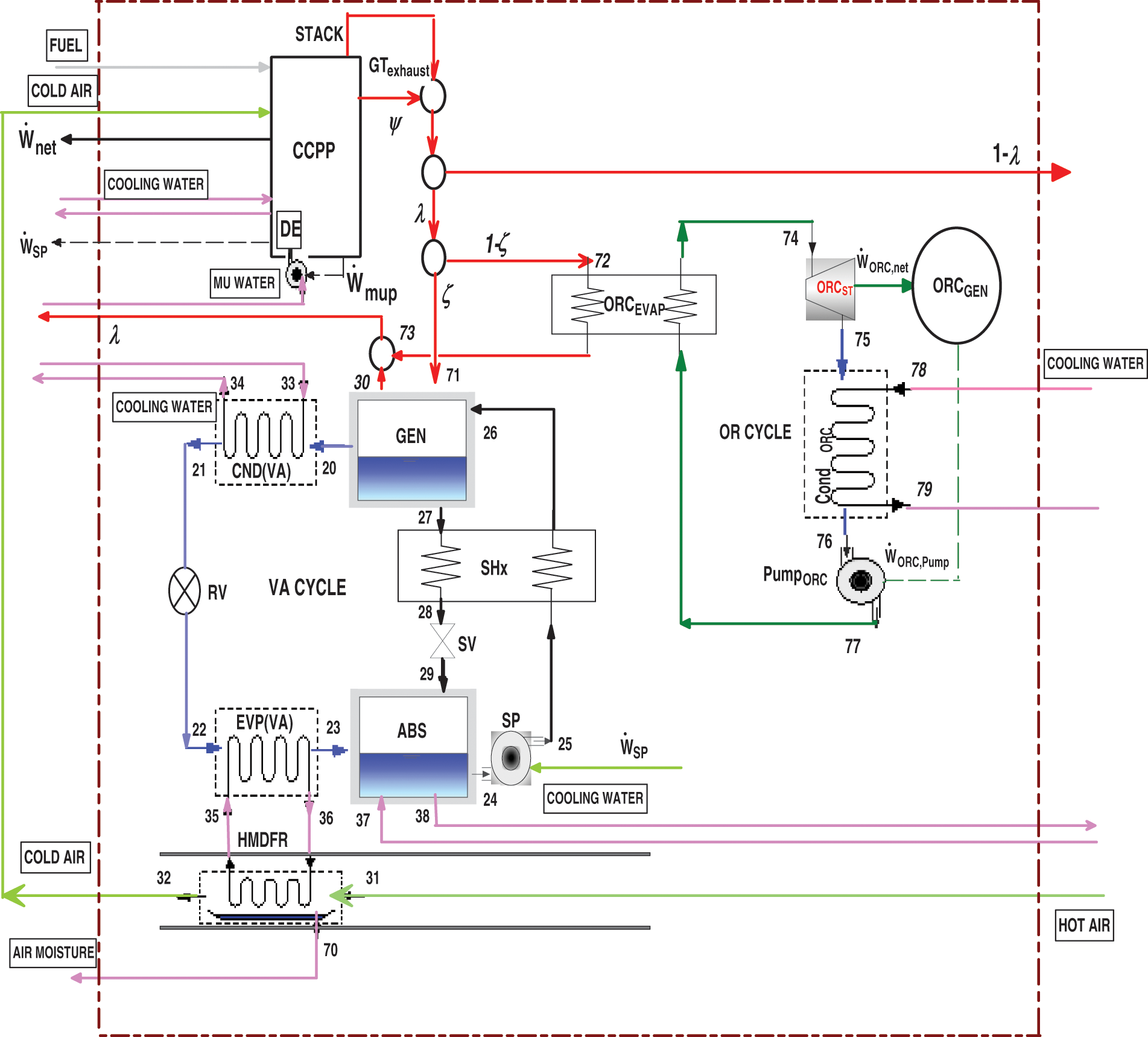
Figure 1: Schematics of modified system CCPP
The heating system and the cooling system are supplied by two separate streams of hot gas. The mass flow rate of hot gas is controlled by dampers to achieve the required mass fractions and to meet the changing needs of heating and cooling. The ORC receives some of the warm gases (1−ξ), which heat the organic fluid and vaporize it to drive the turbine to generate electric power. A portion of the hot gases ξ is delivered to the VARC’s generator, which runs the refrigeration cycle, which cools the humidifier and cools the air compressor’s incoming air to 15 degrees Celsius.
The cooled air is non-isentropically compressed to greater pressure in the GT cycle and T-S diagram of GT is shown in Fig. 2. The combustion chamber uses high-pressure, high-temperature air to burn the fuel. The combustors of the power plant have a can-annular design, which allows the gases from combustion to leave with a pressure drop of around 5% (power plant officials said the drop was between 2% and 8%). The hot gases from combustion then go to the turbine, where they are non-isentropically expanded and generate power for the turbine. A part of the turbine’s output runs the compressor. The GT units’ exhaust gases are sent to the HRSG for the generation of the mainstream, which is then expanded in ST to provide extra W_ ST. ST works on the principle of Rankine cycle and the T-S diagram of Rankine cycle is shown in Fig. 3. The steam goes to a CND after expanding, where it becomes liquid and is sent to a DE by a CP for deaeration and preheating with low-pressure economizer combustion gases. The FWP then pumps the feedwater to a high-pressure storage tank. HPE is used before the EV and SH generate saturated and superheated steam [13]. The system is cooled by a single-effect VAR cycle with a LiBr-H2O working solution and a regenerator. The cooling cycle has high pressure in the generator and condenser, and low pressure in the evaporator and absorber. The rich solution is heated by hot gas in the generator, which makes the refrigerant (H2O) vapors rise. The hot gas is then released into the air, while the refrigerant cools down in the condenser before taking heat from the chilled water in the evaporator. The refrigerant goes to the absorber, where it mixes with the absorbent LiBr, creating a refrigerant-rich LiBr-H2O solution. The absorber is cooled to increase H2O absorption in the LiBr because the temperature and the amount of H2O that can dissolve in LiBr are inversely proportional. The rich solution is moved to the generator (regenerator) by a heat exchanger. The generator separates most of the refrigerant, and the hot weak solution goes through a regenerator, which heats the cold, rich solution that comes from the pump to the regenerator. The weak solution is then reduced to absorber conditions. Organic fluid, heating system, steam turbine, condenser, and solution pump comprise the ORC. The hot gas fraction enters the heating system, where it transfers heat to the organic fluid before being liberated into the atmosphere. The organic fluid expands at high pressures and temperatures in the steam turbine, causing rotational motion. The shaft is attached to the generator, which generates electricity. The low-pressure fluid passes through the condenser, transferring its heat to the cooling water and leaving it at a low temperature and pressure, which then passes through the pump, increasing the pressure [14]. Tozer et al. [15] emphasized the significance of temperature-entropy (T-S) diagrams in quantifying thermodynamic processes. While generalized T-S diagrams have been applied to various absorption cycles, specific diagrams tailored for LiBr/water systems are lacking. Their paper addresses this gap by extending the T-S diagram of water to include curves representing real and ideal LiBr/water absorption cycles. T-S diagram of LiBr/water VAC is shown in Fig. 4 [16].
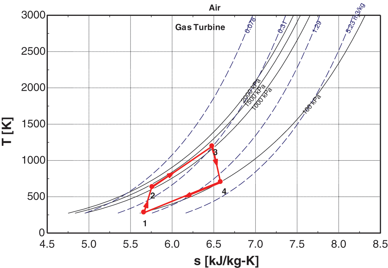
Figure 2: T-S diagram of gas turbine
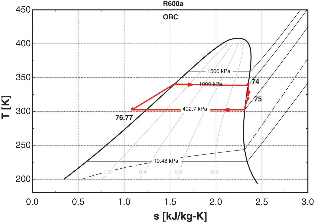
Figure 3: T-S diagram of Rankine cycle
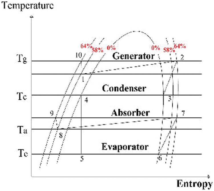
Figure 4: T-S diagram of LiBr/water VAC. Reprinted from Reference [16]
Mathematical modeling plays a very important role in designing and controlling new systems and existing systems, respectively, it helps us to estimate the outcomes of the systems working on different conditions and helps us to figure out the optimum design parameters and conditions.
This paper presents a detailed discussion of the thermodynamic and economic models of each component of the proposed system, based on the first and second laws of thermodynamics and the investment and operating costs.
In Table A1, the assumptions to model the modified CCPP with VAC and ORC are shown which are taken from [17].
To predict various properties of the system under different operating conditions such as enthalpies, entropies, mass flow rate, etc., varying temperatures and atmospheric pressure, etc.
It is widely used in power generation systems, for modeling the different power plants to study their behavior on different operating conditions which helps to predict the optimum conditions and needs of the system at a particular place. Thermodynamic modeling involves the first law and the second law of thermodynamics, every component of the proposed system is modeled accordingly to obey both laws.
The equation of the first law of thermodynamics is mass balance.
The equations of the second law of thermodynamics are
Energy balance
3.2.1 Combined Cycle Power Plant
Applying the above Eqs. (1) and (2) on all the components of the CCPP, we get the relation of individual components which are listed in Table A2.
The mass flow rate of cooling water in the condenser of CCPP can be calculated as
The net power outputs of different units in CCPP can be calculated as
The amount of heat transferred to the CCPP can be calculated as
The energy efficiency of CCPP can be calculated as
3.2.2 Vapor Absorption Chiller
Applying above Eqs. (1) and (2) on all the components of the VAC, we get the relation of the individual components which are listed in Table A3
The coefficient of performance (COP) VAC is the ratio of the amount of heat removed into the evaporator by the refrigerant to the amount of heat given in the generator plus the work consumed by the solution pump to pump the LiBr and water solution from the VAC absorber into the generator. Which can be calculated as
Applying the above Eqs. (1) and (2) on all the components of the ORC, we get the relation of individual components which are listed in Table A4.
The ORC pump used the work from the ORC steam turbine to pump the organic fluid, so the net power output of ORC can be calculated as
The heat from the gas turbine’s exhaust gases is transferred to the organic fluid by the ORC evaporator, which allows the calculation of the as
ORC’s thermal efficiency
The net power output of the proposed system is the sum of all gas turbines, steam turbines, and ORC net power output. Which can be calculated as
The energy utilization factor (EUF) is the ratio of the total useful amount of work to the total amount of work, which shows how much percent of total energy is converted into useful work. This can be calculated as
The economic modeling of modified systems is discussed in detail. To predict the different economic aspects such as the payback period at varying operating conditions.
3.3.1 Vapor Absorption Chiller
The cost functions are used to determine the purchase equipment cost (PEC) for each component of VAC. These functions are defined as the function of power and heat exchanger areas, which are listed in Tables A5 and A6.
Total purchase equipment cost can be calculated as
The levelized cost for ORC can be defined as the ratio of the total annual cost to the total power output of the ORC. Can be calculated as
where TCC and COM are the total capital cost and operating & maintenance cost of the ORC, respectively, whereas N is the number of operating hours in the year and CRF is the total cost recovery factor. Which is calculated as
TCC is calculated as
The cost functions are used to determine the investment capital cost (ICC) for each component of ORC. These functions are defined as the function of power and heat exchanger areas, which are listed in Table A7. Whereas
Results from the current study are compared with those from the literature review to validate the model of the modified CCPP with VAC and ORC, and the percent error acquired from the comparison is employed which is shown in Fig. 5. The system addressed in this paper is a composite of many systems, including CCPP, VAC, and ORC. As a result, each system is independently validated. The results of the CCPP model in this study are compared with the results of the CCPP model in [12].
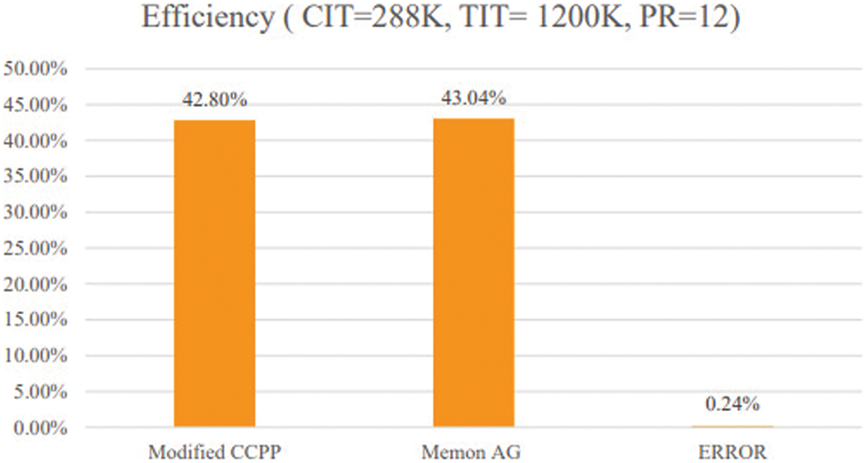
Figure 5: Model validation
The scope of this research is to modify an existing CCPP to utilize its maximum potential to meet the high electrical demands in the summer which should be economic at the same time. In doing so, we will operate the gas turbine under standard conditions and evaluate its performance on different parameters. The objectives of the study are as follows:
1) To develop energy and economic models of modified combined cycles.
2) To conduct parametric-based energy and economic analysis of the modified combined cycle under varying ambient conditions (Temperature, Relative Humidity) and
5 Energy Equation Solver (EES)
The thermodynamic and economic model of the system will be formulated within the Energy Equation Solver (EES) software, leveraging foundational thermodynamic principles such as the First Law of Thermodynamics, energy equation, and mass balance equations. Additionally, essential economic equations, including the total cost function and payback period equations, will be integrated into the model.
Following model development, parametric analysis will be executed utilizing the EES software to assess the system’s performance, energy parameters, and economic indicators under varying ambient conditions. This analytical approach will provide detailed insights into how fluctuations in ambient conditions impact the system’s thermodynamic efficiency, operational robustness, and economic feasibility.
This section presents a detailed discussion of the study’s results. The performance, energy outputs, and PBP of the proposed system at various ambient conditions and the mass fraction of the exhaust gases from the gas turbine exit have been evaluated.
The modified system’s operational parameters are constrained to analyze the consequences and are given in Table A8. Also, thermodynamics parameters of main components are given in Table A9.
6.1 Effects on Fraction of Hot Gases for Cooling and Heating
ξ represents the proportion of exhaust gas mass directed into the VAC’s generator to heat the lithium bromide solution, facilitating the separation of water. This water then enters the condenser to act as a refrigerant in the VAC. The range of ξ spans from zero to one: a higher ξ indicates a larger portion of exhaust gas mass allocated to the VAC, with the remainder (1−ξ) channeled into the ORC for supplementary power generation, and vice versa.
In Figs. 6 and 7, graphs depicting the relationship between ξ and Toutside are presented. It’s evident that as ambient temperature rises, ξ also increases. This is due to the heightened cooling load necessitating greater heat input to the generator for maintaining system operation at a target temperature of 15°C. Consequently, a larger fraction of exhaust gases are directed towards the VAC, while the remaining fraction (1−ξ) is routed to the ORC. Conversely, during lower outside temperatures such as in winter, ξ decreases as the cooling load diminishes, requiring a smaller fraction of exhaust gases. In this scenario, a larger proportion is directed towards the ORC to generate additional power output.
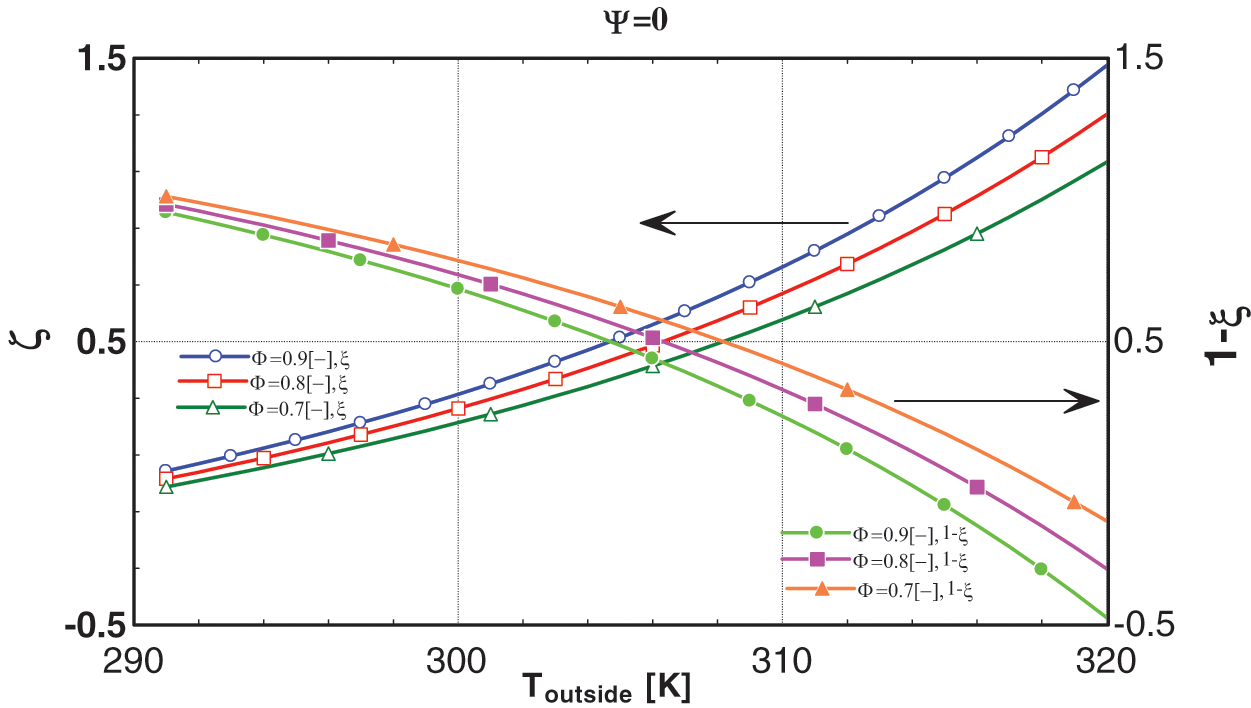
Figure 6: Graphs between ξ, (1−ξ) and Toutside at ψ = 0
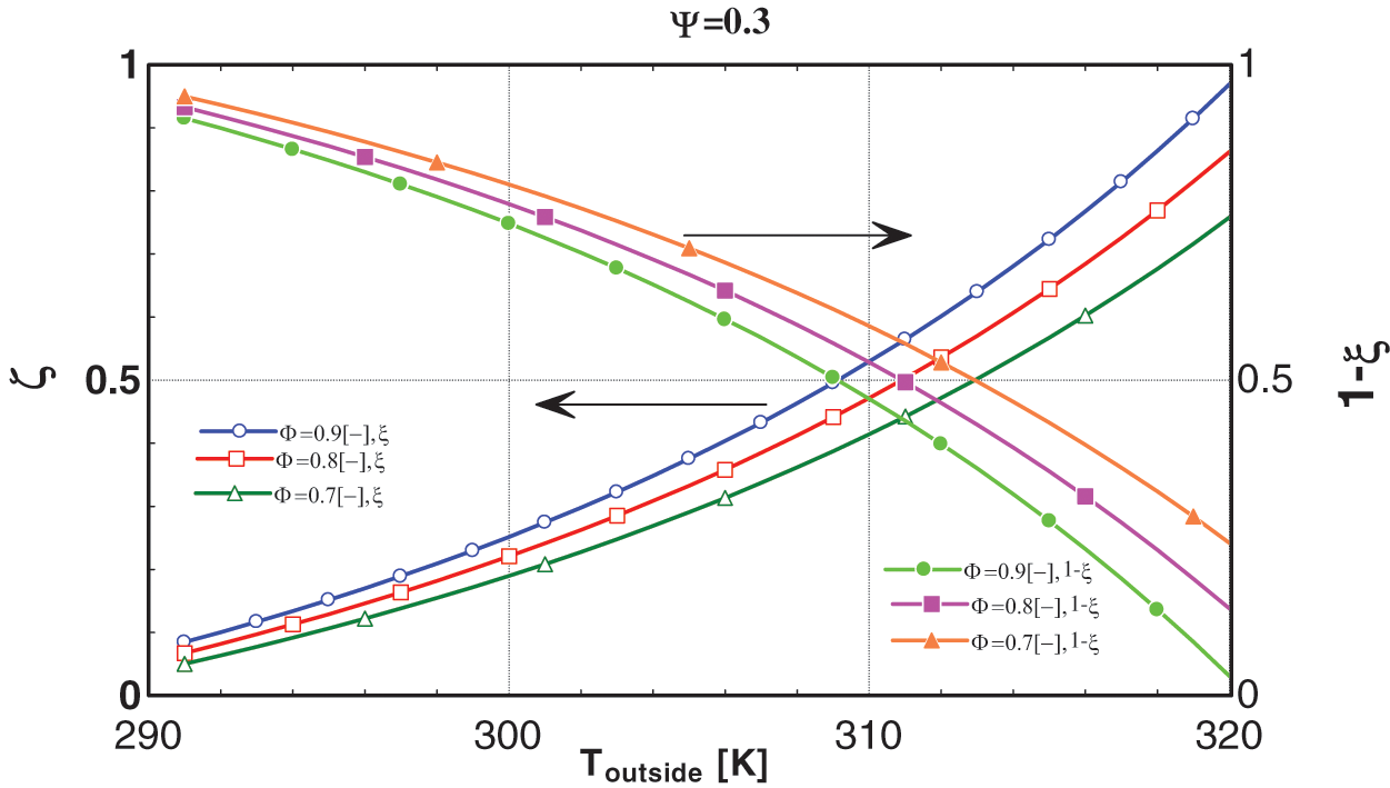
Figure 7: Graphs between ξ, (1−ξ) and Toutside at ψ = 0.3
6.1.2 Mass Fraction of Exhaust Gases
The essence of ψ lies in quantifying the additional energy needed to fulfill the cooling demand. In situations of elevated ambient conditions, the cooling load of the VAC exceeds the capacity of the energy remaining at the exhaust of the stack. Consequently, a fraction of ψ becomes imperative to meet the operational demand, given its heightened energy density relative to the stack exhaust gases.
Plotting the graph between the values of ξ and ψ serves to scrutinize the physical viability of the proposed system. The observed trend illustrates that as the fraction of exhaust gases ψ escalates, the value of ξ diminishes under comparable ambient conditions. This implies that meeting the operational requirements of the system at higher ambient temperatures necessitates either increasing ψ through a control valve or simply disconnecting the ORC, the detailed impacts of which are discussed in Section 6.2. Additionally, in Fig. 6, it is discerned that when ψ is 0 and the outside temperature is 320 K with a relative humidity of 90%, the value of 1−ξ falls below zero, which contravenes the idea of the physical application of the proposed system because according to the second law of thermodynamics, this suggests that the ORC must perform work on the system to meet the cooling load. Conversely, in Fig. 7, as ψ increases to 0.15 under the same ambient conditions, the value of 1−ξ reaches zero, indicating that the ORC will be disconnected. It is concluded that at high ambient conditions, to operate the system it is mandatory to utilize the ψ.
To assess the performance of the modified system, both the Energy Utilization Factor (EUF) and the efficiency of the system are taken into consideration. The system’s efficiency, defined as the ratio of total power output to the supplied heat energy, is compared with that of the original system located in Kotri. This comparative analysis aims to scrutinize the practical feasibility of the proposed concept.
In Figs. 8 and 9, graphs illustrating the relationship between Toutside and system performance reveal that as Toutside increases, the efficiency of the original system decreases. This is attributed to the decrease in air density with rising temperature, causing the gas turbine’s air compressor to require more energy to compress the same volume of air due to fixed compressor volume. Conversely, the efficiency of the proposed system is notably higher, aligning with the study’s concept. Furthermore, the efficiency of the modified system remains constant as it operates at a fixed temperature of 15°C.
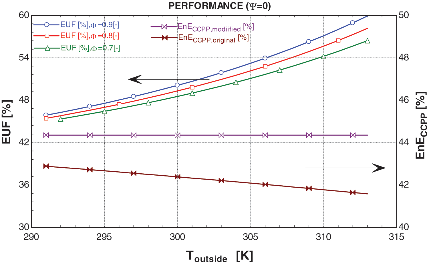
Figure 8: Graphs between performance and Toutside at ψ = 0
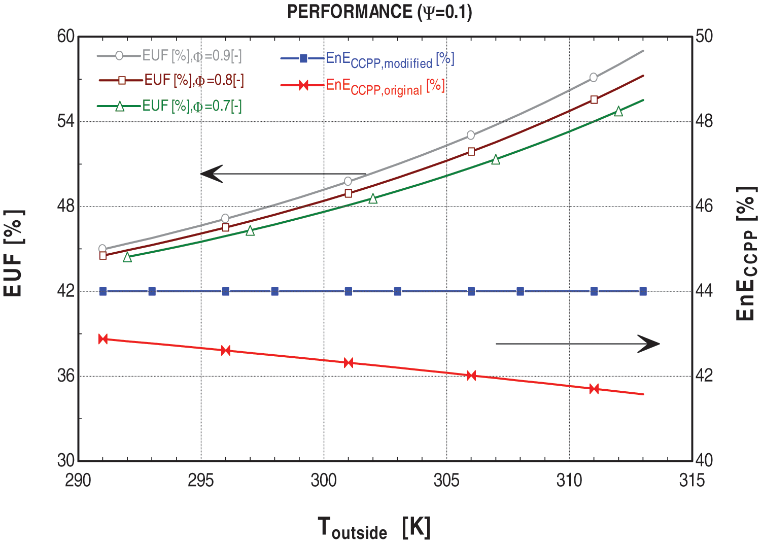
Figure 9: Graphs between performance and Toutside at ψ = 0.1
The Energy Utilization Factor (EUF) of a system, defined as the ratio of all useful energy output to the supplied energy in terms of fuel, indicates the percentage of energy utilized during the cycle. The EUF of the proposed system increases with higher ambient conditions. This is because the modified system initially cools the ambient air to 15°C, utilizing energy from exhaust gases expelled from the stack and gas turbine outlet. As Toutside rises, the cooling load increases, requiring more energy to achieve the 15°C cooling target compared to lower Toutside conditions. The remaining exhaust gases, after meeting the cooling demand, are then utilized in the ORC. Consequently, the EUF of the proposed system consistently surpasses that of the original system and increases with ambient conditions, reflecting the system’s utilization of exhaust gases for various purposes at the expense of the same fuel energy.
From an environmental standpoint, the results are highly significant, as the proposed system yields exhaust gases with lower energy content compared to the original system in the environment, thereby supporting the study’s underlying concept.
6.2.2 Mass Fraction of Exhaust Gases
The concept of Ψ is elaborated upon in Section 6.1.2. In Figs. 8 and 9, graphs depicting the relationship between Toutside and system performance at various values of Ψ demonstrate that as Ψ increases, the efficiency of the modified system decreases, and vice versa. This phenomenon is elucidated in Section 6.1.2, where Ψ is utilized during peak demands, and its value escalates with ambient conditions. When a greater portion of high-energy exhaust from the gas turbine outlet is diverted to work in the VAC to meet cooling demands, the flow rate for the HRSG decreases, consequently the decrease in the overall efficiency of the modified CCPP.
Furthermore, the Energy Utilization Factor (EUF) is unaffected by Ψ but solely influenced by ambient conditions. This section serves to provide a concise overview of the modifications in terms of performance. The comparison indicates that the modified system exhibits greater efficiency than the original system, irrespective of ambient conditions and the value of Ψ. This finding supports the notion of the physical viability of the proposed system.
The primary objective of the energy output graphs is to determine the optimal operational conditions for the system, ensuring the most efficient meeting of energy demands. This section extensively discusses the effects of ambient conditions on the system’s energy outputs. So far, we have examined how ambient conditions influence various parameters, supporting the physical viability and necessity of the system. Energy outputs are paramount in discussions regarding power generation, and the research gap addressed in this study aims to propose a system capable of efficiently and economically meeting peak energy demands.
In Figs. 10–13, it is evident that irrespective of ambient conditions, the work outputs of the proposed system’s CCPP consistently surpass those of the original system under similar conditions. Furthermore, the total output of the proposed system, comprising the modified CCPP and the ORC work output, consistently exceeds that of the original system. This indicates the feasibility of cooling the air to 15°C for the gas turbine with the aid of a VAC and operating the ORC using the CCPP exhaust to meet energy requirements.
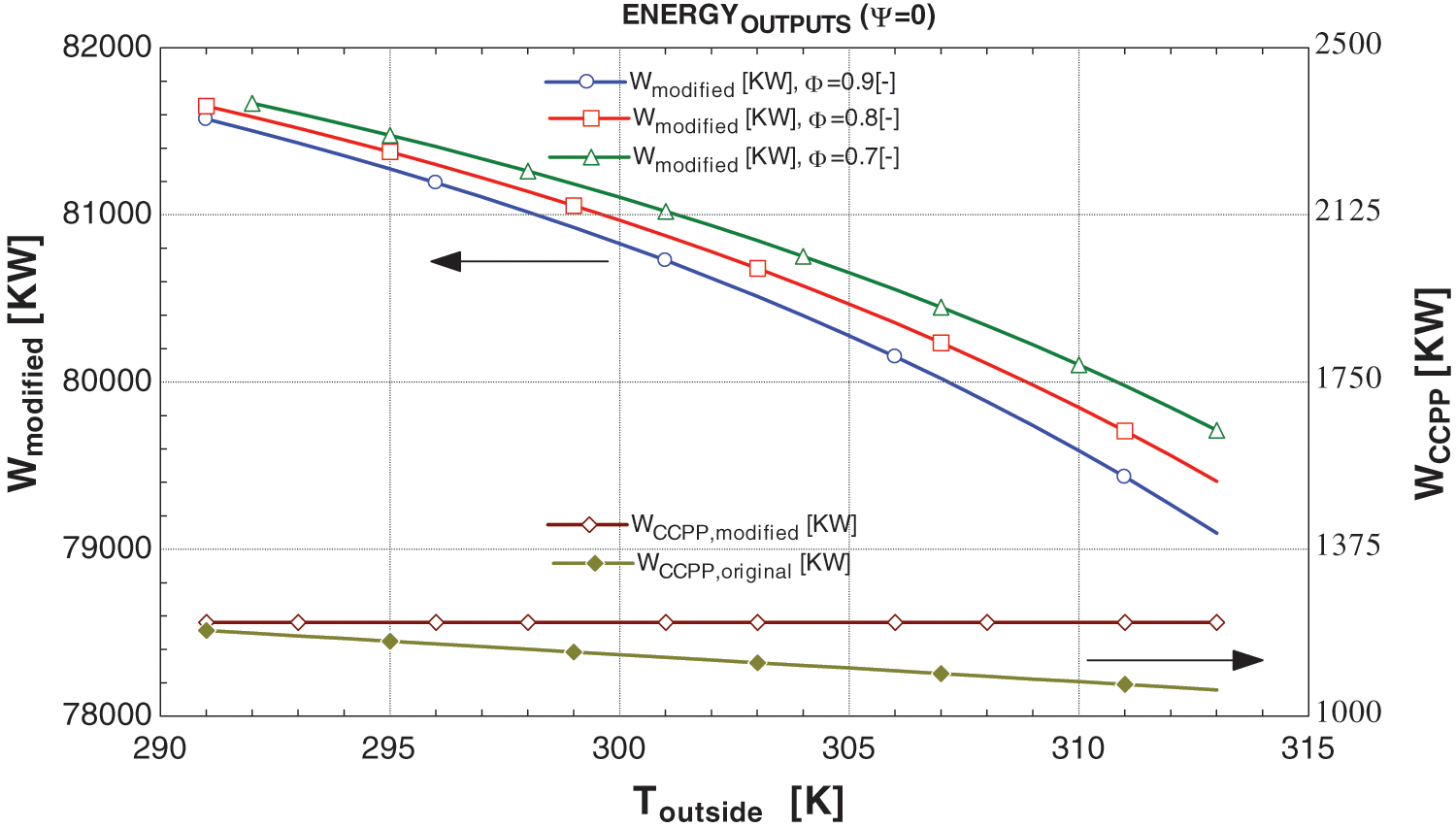
Figure 10: Graphs between energy outputs and Toutside at ψ = 0
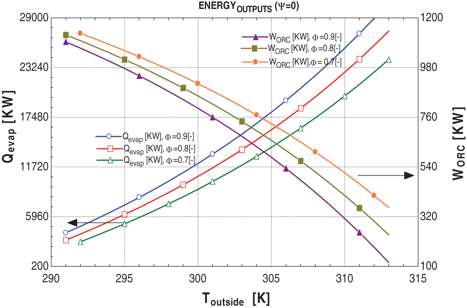
Figure 11: Graphs between energy outputs and Toutside at ψ = 0.1
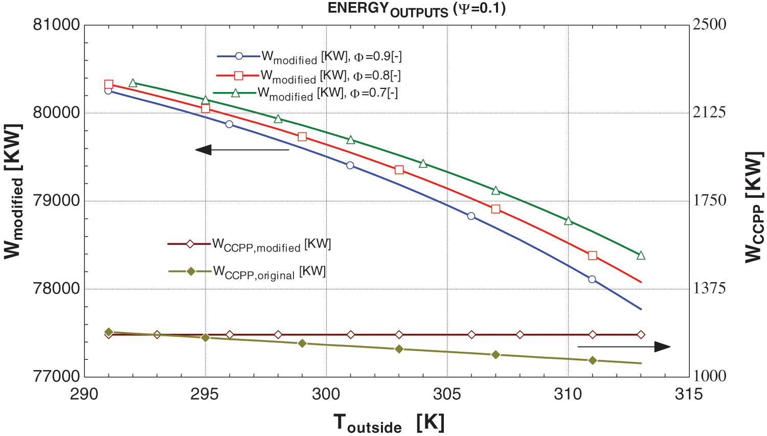
Figure 12: Graphs between energy outputs and Toutside at ψ = 0
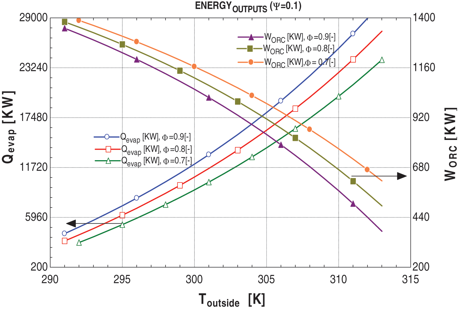
Figure 13: Graphs between energy outputs and Toutside at ψ = 0.1
Moreover, ambient conditions also affect additional outputs, namely the cooling load and work output of the ORC. The relationship between the cooling load of the VAC and the power output of the ORC in the modified system is inversely proportional; as ambient conditions increase, the cooling load rises while the ORC’s power output decreases, and vice versa. This phenomenon arises from the primary focus of the study on air cooling. Physically, when the thermosets of the modified system sense ambient temperature, the control valve regulating the value of ξ adjusts automatically according to the cooling requirements. If the value of ξ is adequate to meet the cooling demand, any surplus is directed toward the ORC. However, if ξ falls short, the system automatically adjusts the control valve of Ψ. Further, the after-effects of the Ψ is discussed in Section 6.3.2.
6.3.2 Mass Fraction of Exhaust Gases
As discussed, the significance of the ψ value lies in determining the optimal operational parameters of the system to fulfill the energy requirements. Figs. 10–13 indicate that the ψ value has no discernible impact on cooling load. However, it does exhibit an inversely proportional relationship with the power outputs of the CCPP and directly with the power output of the ORC. Lower ψ values correspond to higher power output from the CCPP and lower power output of ORC, and vice versa.
In practice, increasing the ψ value is typically not the primary choice. As depicted in Figs. 11 and 13, raising the ψ value can lead to a decrease in the CCPP’s power output, even below that of the original system. However, the overall power output increases due to the enhanced power output of the ORC. While this technically validates the necessity of the proposed system, the marginal difference may render the system uneconomical to operate with these modifications. This aspect is further elaborated in Section 6.4.
The correlation arises from the fundamental calculation of the payback period, which compares the total system cost to the additional savings it generates. Figs. 14 and 15 depict the relationship between ambient conditions, equipment cost, and the payback period. Higher ambient conditions correspond to a higher system cost. This phenomenon occurs because, with rising outside temperatures, a larger heat exchanger area is required for efficient heat transfer, consequently increasing the total system cost. This increase is significantly influenced by the cost equations used for analysis, where the heat exchanger area plays a crucial role.
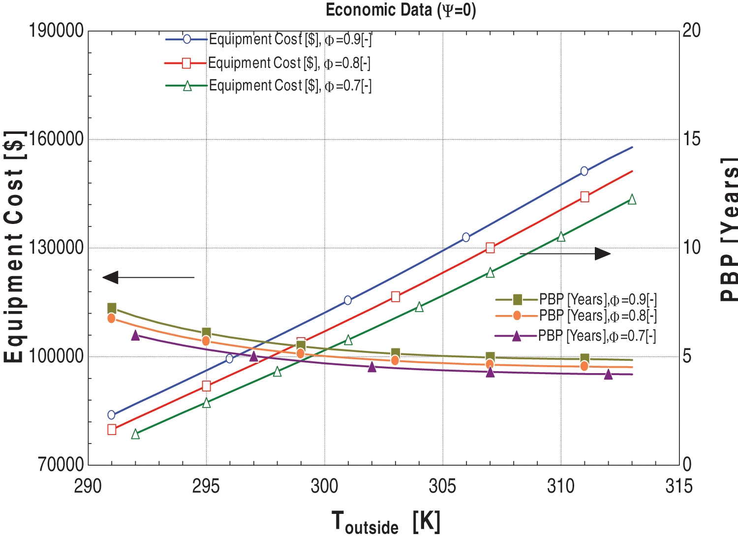
Figure 14: Graphs between economic data and Toutside at ψ = 0
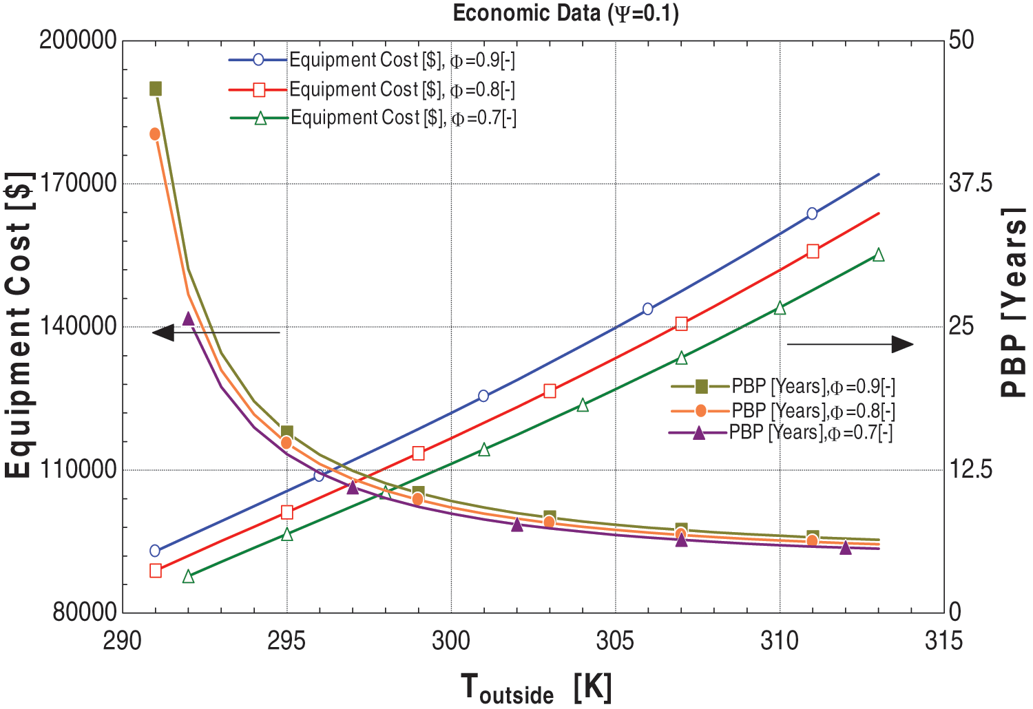
Figure 15: Graphs between economic data and Toutside at ψ = 0.1
Moreover, the increase in outside temperature leads to a reduction in the work output of the ORC, as discussed previously. This decrease in work output results in diminished additional power savings, causing an increase in the payback period. However, according to the results, the payback period decreases with temperature. This occurs because, technically, at higher temperatures, the gas turbine does not work efficiently (which is the research gap of the study). Consequently, the original system will produce less power than it would under lower ambient conditions.
Furthermore, the proposed system’s gas turbine always operates at 288 K regardless of ambient conditions, resulting in a greater power output than the original system. Due to the increase in the difference in power outputs between the original and proposed systems with changing ambient conditions, the payback period of the system starts decreasing with higher ambient conditions, regardless of the decrease in the ORC power output.
6.4.2 Mass Fraction of Exhaust Gases
In this section, we delve into the impact of the variable ψ on both the payback period and equipment costs, crucial considerations for practical viability and economic operation of the system. Firstly, as previously discussed, equipment costs increase with ambient conditions, but they also rise with higher values of ψ. This is attributed to the inclusion of the ORC in equipment costs, which is influenced by the area of the heat exchanger. In Section 6.1.2, a higher ψ value directs more residual energy towards the ORC, necessitating larger heat exchanger areas to facilitate heat transfer, thereby elevating overall equipment costs.
Furthermore, as discussed earlier, increasing ψ yields positive results in terms of system performance and energy outputs, endorsing the proposed system. However, from an economic standpoint, raising ψ is not advisable. In practical terms, when exhaust gases are extracted from the gas turbine outlet to power the VAC and ORC and fulfill ambient demand, it comes at the expense of decreased power output from the CCPP. Utilizing energy from the gas turbine outlet leaves less energy available to operate the steam turbine, resulting in lower power generation and decreased CCPP output. Consequently, the reduced disparity between the original system and the proposed system’s power output leads to an extended payback period.
This paper discusses the energy, economic, and performance analysis of a modified CCPP with ORC and VAC to cool the ambient air to meet the design conditions of the gas turbine and generate additional power. Parametric studies have been carried out on varying ambient conditions and fractions of exhaust gases from the outlet of the gas turbine. An engineering equation solver (EES) is used to model the system. Results are validated and a comparison is carried out between energy outputs and performance of the original system with the modified system. Moreover, the effects on PBP are also disused on varying ambient conditions and with different values ψ. The important findings are summarized as follows:
• Through the modification, there is an overall increase in the system’s efficiency which depends on the operating conditions.
• At the higher ambient conditions the performance of the original system is decreased whereas the modified system always works at 15°C so the efficiency remains constant and the overall energy utilization factor (EUF) increases and vice versa.
• The value of ψ lies between 0–1, the higher the value higher the mass fraction from the gas turbine outlet is routed towards VAC and ORC. With increasing the value of ψ the efficiency of the modified system becomes lower than at low values of ψ.
• Energy outputs vary with operating conditions, as discussed above the modified plant output is more than the original one at higher ambient conditions, and Kotri’s average temperature value is around 30 C. so the modified system will work more effectively otherwise at high peak loads and demands value of should be adjusted accordingly ψ.
• The payback period and equipment cost of the system are subject to variation based on operating conditions. It’s notable that in certain ambient conditions, opting for higher values of ψ to fulfill heightened electrical demands isn’t economically justified. This is primarily due to the resultant increase in equipment costs and elongated payback periods for the system. Therefore, the utilization of ψ should be regarded as a final option, to be considered only after exploring other options.
After conducting a comprehensive analysis, it has been determined that the system shows promise for areas with environmental conditions akin to Kotri, Pakistan. However, regions facing extreme weather patterns may require alterations in the system’s design, a consideration that was not explored in the current study.
Furthermore, it has been noted that during periods of high temperatures, the system’s performance heavily relies on the parameter ψ, which directly influences the power generation of the CCPP. In light of this, employing artificial intelligence (AI) to design an artificial neural network for the system could prove beneficial. By training the system on various ambient conditions and values of ψ, optimal operating conditions can be achieved. A technically sound approach involves implementing an adaptive design capable of adjusting to ambient conditions. For instance, when the ambient temperature drops to or below 15°C, the system should deactivate the VAC and prioritize directing maximum exhaust energy towards operating ORC to enhance power output and meet demand requirements.
As for prospects, it is recommended to conduct an environmental analysis of the system to ascertain the energy content in the exhaust emissions. This analysis could reveal opportunities for integrating additional equipment to enhance the overall output of the system and improve its environmental impact.
For future endeavors, particularly in industrial applications, it’s advisable to undertake the design and analysis of the proposed system tailored to specific cities, taking into account their unique ambient conditions. The objective would be to determine optimal operating conditions under various circumstances to economically fulfill energy demands. Such a design should encompass crucial aspects including working parameters, equipment costs, payback periods, environmental impacts, and more. By conducting comprehensive analyses tailored to specific locations, it becomes possible to devise systems that are not only efficient but also economically viable and environmentally sustainable.
Acknowledgement: All authors express gratitude for the support and cooperation provided by their respective institutions.
Funding Statement: The authors did not receive any dedicated funding for this research.
Author Contributions: The authors confirm their contribution to the paper as follows: Study conception and design: Abdul Moiz and Abdul Ghafoor Memon; data collection: Malik Shahzaib; analysis and interpretation of results: Abdul Moiz; draft manuscript preparation: Abdul Moiz, Laveet Kumar and Mamdouh El Haj Assad. All authors reviewed the results and approved the final version of the manuscript.
Availability of Data and Materials: All relevant data are included within the paper.
Ethics Approval: Not applicable.
Conflicts of Interest: The authors declare that they have no conflicts of interest to report regarding the present study.
References
1. M. Reshaeel, A. Javed, A. Jamil, M. Ali, M. Mahmood and A. Waqas, “Multiparametric optimization of a reheated organic Rankine cycle for waste heat recovery based repowering of a degraded combined cycle gas turbine power plant,” Energy Convers. Manag., vol. 254, 2022, Art. no. 115237. doi: 10.1016/j.enconman.2022.115237. [Google Scholar] [CrossRef]
2. S. Klein and G. Nellis, “Refrigeration and heat pump cycles,” in Thermodynamics. USA: Cambridge University Press, 2012. [Google Scholar]
3. M. F. Qureshi, M. W. Chandio, A. A. Memon, L. Kumar, and M. M. Awad, “Thermal analysis of solar energy based organic Rankine cycle cascaded with vapor compression refrigeration cycle,” Energy Nexus, vol. 14, 2024, Art. no. 115237. doi: 10.1016/j.nexus.2024.100291. [Google Scholar] [CrossRef]
4. D. Thanganadar, F. Asfand, and K. Patchigolla, “Thermal performance and economic analysis of supercritical Carbon Dioxide cycles in combined cycle power plant,” Appl. Energy, vol. 255, Dec. 1, 2019, Art. no. 113836. doi: 10.1016/j.apenergy.2019.113836. [Google Scholar] [CrossRef]
5. M. M. Ehsan, Z. Guan, and A. Y. Klimenko, “A comprehensive review on heat transfer and pressure drop characteristics and correlations with supercritical CO2 under heating and cooling applications,” Renew. Sustain. Energ. Rev., vol. 92, no. 1, pp. 658–675, Sep. 1, 2018. doi: 10.1016/j.rser.2018.04.106. [Google Scholar] [CrossRef]
6. H. H. Erdem and S. H. Sevilgen, “Case study: Effect of ambient temperature on the electricity production and fuel consumption of a simple cycle gas turbine in Turkey,” Appl. Therm. Eng., vol. 26, no. 2, pp. 320–326, Feb. 1, 2006. doi: 10.1016/j.applthermaleng.2005.08.002. [Google Scholar] [CrossRef]
7. A. P. P. Santos, C. Andrade, and E. Zaparoli, “Comparison of different gas turbine inlet air cooling methods,” World Acad. Sci. Eng. Technol., vol. 61, pp. 40–45, Jan. 1, 2012. [Google Scholar]
8. R. Porumb, B. Porumb, and M. Balan, “Numerical investigation on solar absorption chiller with LiBr-H2O operating conditions and performances,” Energy Proc., vol. 112, pp. 108–117, Mar. 1, 17. doi: 10.1016/j.egypro.2017.03.1071. [Google Scholar] [CrossRef]
9. A. Darwish Ahmad, A. M. Abubaker, Y. S. H. Najjar, and Y. M. A. Manaserh, “Power boosting of a combined cycle power plant in Jordan: An integration of hybrid inlet cooling & solar systems,” Energy Convers. Manag., vol. 214, no. 8, Jun. 15, 2020, Art. no. 112894. doi: 10.1016/j.enconman.2020.112894. [Google Scholar] [CrossRef]
10. M. Ridha, J. Al-Tameemi, S. Yahya, A. Hafedh, and I. Azzawi, “Thermodynamic optimization of an integrated gas turbine cycle, heat exchanger and organic Rankine cycle for co-generation of mechanical power and heating load,” J. Comput. Appl. Res. Mech. Eng., vol. 13, no. 1, pp. 75–88, May 23, 2023. doi: 10.22061/jcarme.2023.9366.2253. [Google Scholar] [CrossRef]
11. M. N. Khan and I. Tlili, “New advancement of high performance for a combined cycle power plant: Thermodynamic analysis,” Case Stud. Therm. Eng., vol. 12, no. 1, pp. 166–175, Sep. 1, 2018. doi: 10.1016/j.csite.2018.04.001. [Google Scholar] [CrossRef]
12. I. Njoku, C. Oko, and J. C. Ofodu, “Performance evaluation of a combined cycle power plant integrated with organic Rankine cycle and absorption refrigeration system,” Cogent Eng., vol. 5, Mar. 3, 2018, Art. no. 1451426. doi: 10.1080/23311916.2018.1451426. [Google Scholar] [CrossRef]
13. A. Memon, R. Memon, and S. Qureshi, “Thermo-environmental and economic analyses of combined cycle power plants with regression modelling and optimization,” Appl. Therm. Eng., vol. 125, pp. 489–512, Jun. 1, 2017. doi: 10.1016/j.applthermaleng.2017.06.139. [Google Scholar] [CrossRef]
14. M. Asim et al., “Performance assessment and working fluid selection for novel integrated vapor compression cycle and organic Rankine cycle for ultra low grade waste heat recovery,” Sustainability, vol. 13, no. 21, 2021, Art. no. 11592. doi: 10.3390/su132111592. [Google Scholar] [CrossRef]
15. R. Tozer, A. Syed, and G. Maidment, “Extended temperature-entropy (T-s) diagrams for aqueous lithium bromide absorption refrigeration cycles,” Int. J. Refrig., vol. 28, no. 5, pp. 689–697, Aug. 1, 2005. doi: 10.1016/j.ijrefrig.2004.12.010. [Google Scholar] [CrossRef]
16. F. A. F. Ali and A. M. E. Yoonis, “Absorption refrigeration cycle technology,” in Cooling Technologies, B. -H. David, Ed., Rijeka: IntechOpen, 2023. [Google Scholar]
17. A. G. Memon and R. A. Memon, “Thermodynamic analysis of a trigeneration system proposed for residential application,” Energy Convers. Manag., vol. 145, no. 9, pp. 182–203, Sep. 1, 2017. doi: 10.1016/j.enconman.2017.04.081. [Google Scholar] [CrossRef]
Appendix A


Cite This Article
 Copyright © 2024 The Author(s). Published by Tech Science Press.
This work is licensed under a Creative Commons Attribution 4.0 International License , which permits unrestricted use, distribution, and reproduction in any medium, provided the original work is properly cited.


 Submit a Paper
 Propose a Special lssue
 View Full Text
 Download PDF
 Downloads
 Citation Tools