
 Submit a Paper
 Propose a Special lssue
 Open Access
ARTICLE

Plasma Surface Modification of Li2TiSiO5 Anode for Lithium-Ion Batteries
1 School of Materials Science and Engineering, Tianjin University, Tianjin, 300072, China
2 School of Mechanical Engineering and Rail Transit, Changzhou University, Changzhou, 213164, China
3 Zhejiang Sunoren Solar Technology Co., Ltd., Haining, 314400, China
* Corresponding Author: Shangqi Sun. Email:
Energy Engineering 2024, 121(10), 2769-2776. https://doi.org/10.32604/ee.2024.052680
Received 11 April 2024; Accepted 12 July 2024; Issue published 11 September 2024
 View Full Text
 Download PDF
Abstract
Solving intrinsic structural problems such as low conductivity is the main challenge to promote the commercial application of Li2TiSiO5. In this study, Li2TiSiO5 is synthesized by the sol-gel method, and the surface modification of Li2TiSiO5 is carried out at different temperatures using low-temperature plasma to enhance its lithium storage performance. The morphological structure and electrochemical tests demonstrate that plasma treatment can improve the degree of agglomeration. The peak position of the plasma-treated Li2TiSiO5 is shifted to a lower angle, and the shift angle increases with increasing sputtering power. Li2TiSiO5 after 300 W bombardment shows excellent capacity (144.7 mA·hg−1 after 500 cycles at 0.1 Ag−1) and rate performance (140 mA·hg−1 at 5 Ag−1). Electrochemical analysis indicates that excellent electrochemical performance is attributed to the enhancement of electronic and ionic conductivity by plasma bombardment.Keywords
Nomenclature
| GR | Guaranteed Reagent |
| CP | Chemically Pure |
| AR | Analytical Reagent |
Realizing carbon peak and carbon neutrality is an effective strategy for countries around the world to address global climate change and energy crises, as it can promote the substitution of traditional energy with new renewable energy sources and have a significant impact on industrial structure [1]. In recent years, energy storage devices represented by lithium-ion batteries (LIBs) have been used as the primary solution for storing effective renewable energy [2]. However, among various commercially reported anode materials for lithium batteries, graphite tends to form lithium dendrites easily during charge and discharge at high current densities [3], while another negative electrode material, lithium titanate, is limited by its capacity and high operating potential, failing to meet the expectations of electronic devices for high energy density [4].
Currently, Li2TiSiO5 (LTSO) with a silicate-based poly-anionic structure has emerged as a potential alternative to lithium battery negative electrode materials due to its advantages of high theoretical capacity (308 mA·hg−1), appropriate redox potential (~0.28 V vs. Li/Li+), and high stability [5,6]. However, the inherently low electronic/ionic conductivity of LTSO leads to reduced reversible capacity and rate performance during charge and discharge processes. To address these issues, researchers have carried out surface modifications through methods such as conductive coating encapsulation, morphology control, and defect engineering [7]. For example, Wang et al. loaded LTSO onto carbon nanofibers, and the unique three-dimensional interconnected nanostructure enhanced the pseudocapacitive effect of LTSO, maintaining a capacity of 50% at a rate of 10 Ag−1 [8]; Mei et al. systematically studied the effect of niobium doping on LTSO, and the results showed that the introduction of niobium improved the intrinsic electronic conductivity of LTSO and enhanced lithium ion migration kinetics, achieving a high capacity of 125.6 mA·hg−1 at 0.5 Ag−1 [9].
In recent years, plasma technology has been widely applied in defect engineering of electrode materials. Plasma is a state of matter generated by ionizing gas molecules at high energy levels, containing various particles such as positive and negative ions, electrons, neutral particles, and free radicals [10]. These particles possess high energy and chemical activity under the action of an electric field, capable of undergoing a series of physical and chemical reactions and interactions with material surfaces. Among them, the high-energy active particles generated by plasma excitation can cause etching effects when bombarding the material surface. When the bombardment energy is higher than the surface atomic binding energy, atoms can overflow from the material surface, forming defects such as atomic vacancies. Wu et al. controlled the oxygen vacancy content in Co3O4 through plasma treatment and found that oxygen vacancies could assist P doping to enhance ion diffusion kinetics, electronic conductivity, and structural stability [11]. Additionally, plasma doping can promote high-energy atoms, molecules, and ions to dope into the host material through a high-energy field, achieving doping of different elements and their different forms, increasing defects and active sites, and improving interface adsorption capability, endowing materials with better electrochemical performance [12]. Zhou et al. adopted a plasma gradient nitrogen doping strategy to modify the surface and sub-surface of garnet electrolytes, which can not only etch surface impurities but also form a rich Li3N interface between the solid electrolyte and lithium anode in situ [13].
Based on this, this work utilizes low-temperature plasma technology to explore the factors affecting the morphology, structure, and electrochemical properties of LTSO through scheme design. The research found that low-temperature plasma can improve the degree of material aggregation and enhance the intrinsic electronic/ionic conductivity of LTSO through high-energy particle sputtering, thereby improving its electrochemical performance.
The materials and reagents used in the experiments, including cyclopentylsilane (CP), tetrabutyl titanate (CP), lithium hydroxide (GR), Super P (from Japan Kanto), N-methyl-2-pyrrolidone (AR), polyvinylidene fluoride (GR), and anhydrous ethanol (AR), are all purchased from Aladdin Chemical Reagent Co., Ltd., Shanghai, China.
2.2 Materials Preparation and Characterization
The LTSO synthesis is conducted via sol-gel method at room temperature, weighing titanium butoxide (1.70 g) and positively silicon tetraethoxide (1.04 g) according to the stoichiometric ratio, and mixing them with 20 mL of ethanol to form a solution. Lithium hydroxide (0.42 g) is dissolved in 20 mL of water to prepare a solution. The lithium hydroxide solution is then added into the ethanol solution, followed by stirring for 15 min and ultrasonication to obtain a white powder. The white powder is annealed in air at 870°C with a heating rate of 5°C·min−1 for 8 h and naturally cooled to room temperature, yielding LTSO.
The LTSO is laid flat on the sample stage of a radio frequency plasma apparatus, with a thickness not exceeding 1 µm. The chamber is sealed, evacuated to below 1 Pa, and filled with 100 mL·min−1 of argon gas. Plasma is generated at a power of 300 W for 15 min, followed by cooling to room temperature.
Structural analysis is conducted using X-ray diffractometer (XRD) with Cu Kα radiation (λ = 0.154) in the 5–80° angular range at a scan rate of 0.5° min−1. Morphological analysis is carried out using a field emission scanning electron microscope (SEM). For ease of description, the original sample and LTSO treated at 300 W are named LTSO-0 and LTSO-300, respectively.
The sample, polyvinylidene fluoride, and Super P are ground in a mortar at a ratio of 8:1:1, then enough N-methyl pyrrolidone is added and stirred evenly before being coated on a battery-grade copper foil. The loading amount of the active material on the copper foil is measured to be approximately 1.74 mg·cm−2. Celgard 2400 as the separator, and a 1 M LiPF6 in ethylene carbonate and dimethyl carbonate solution (EC + DMC, 1:1) as the electrolyte. All batteries are subjected to comprehensive charge and discharge within a voltage range of 0.01~3 V using a LAND CT2001C battery testing system. Electrochemical impedance spectroscopy (EIS) (0.1–100 kHz, 5 mV) and cyclic voltammetry tests are performed on a CHI660E electrochemical workstation.
The SEM images of LTSO-0, synthesized via the sol-gel method, and LTSO-300 post-plasma treatment are depicted. As delineated in Fig. 1a, the original LTSO-0 showcases an irregular granular morphology with dimensions smaller than 300 nm. Nevertheless, these granules densely conglomerate into block-like structures, as discerned in the magnified image at the top right corner, evincing a lack of discernible pores on the surface of these formations. Upon plasma treatment, the morphology of LTSO-300 unveils a porous distribution with heightened dispersion in Fig. 1b, wherein the size of the block-like structures markedly diminishes, assuming irregular contours. The magnified image in the top right corner illustrates an amplified degree of dispersion amidst the particles. This augmented dispersion of LTSO augments electrolyte infiltration and diminishes interfacial charge transfer resistance.
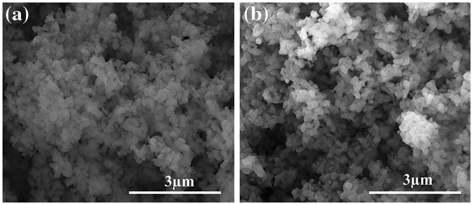
Figure 1: SEM images of LTSO-0 (a) and LTSO-300 (b)
As delineated in Fig. 2a, both the pristine and treated LTSO manifest a tetragonal structure (JCPDS# 82-1955) [14]. The diffraction peaks observed at 20.1°, 24.4°, 27.6°, and 34.4° correspond to the (001), (101), (200), and (201) crystal planes of Li2TiSiO5 [15], respectively. The XRD pattern of LTSO-300 exhibits akin diffraction peaks to LTSO, implying an unaltered crystal structure post-plasma treatment. Upon magnification of the (200) peak across all samples, as depicted in Fig. 2b, the (200) peak of plasma-treated LTSO is notably shifted to the left. This subtle angular deviation of the peak signifies an expansion of the lattice spacing, potentially ascribed to the formation of Ti3+ species with enlarged ionic radii and wider van der Waals gaps, owing to oxygen vacancies [16].
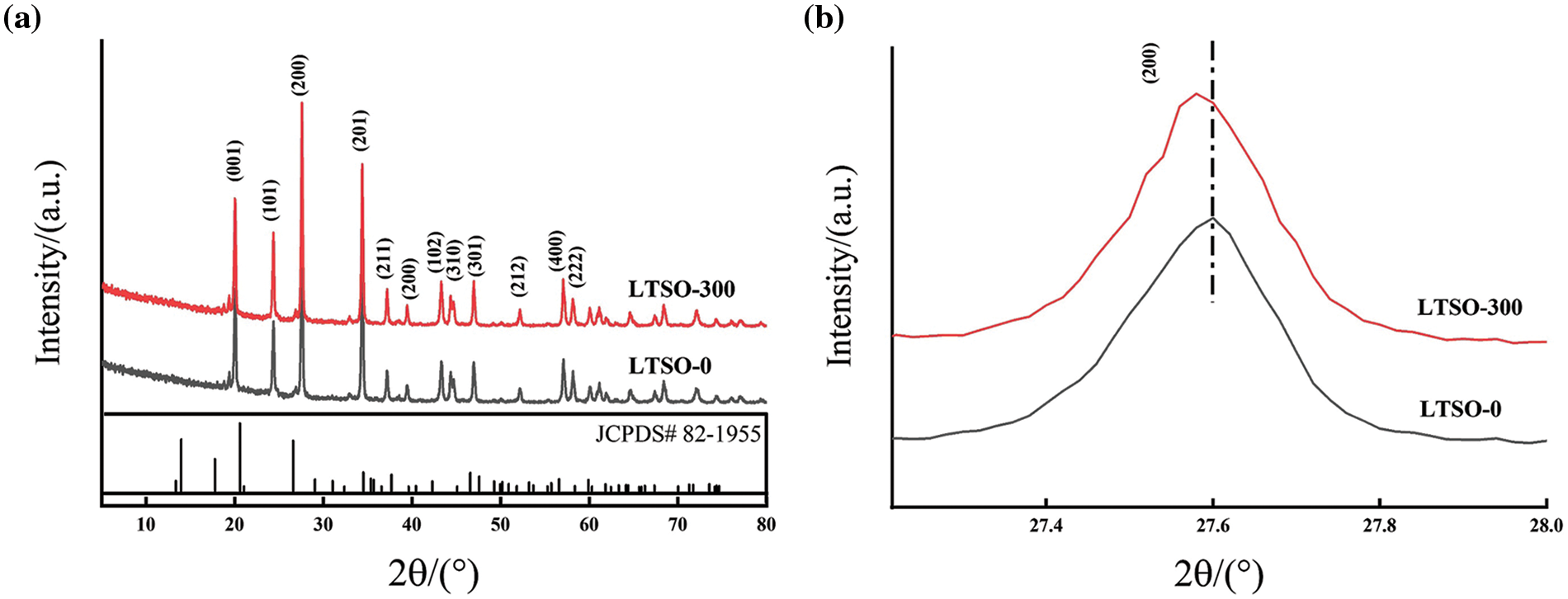
Figure 2: XRD patterns (a) and magnification image (b) of 200 peak of LTSO-0 and LTOS-300
Fig. 3a illustrate the cyclic voltammetry (CV) profiles of LTSO-0 for the initial three cycles at 0.1 mVs−1. It is noted that LTSO-0 exhibits certain irreversible cathodic peaks during the inaugural discharge process, with the peak around 0.61 and 1.2 V corresponding to electrolyte decomposition, irreversible product formation, and the emergence of an intermediate phase between the solid electrolyte and electrolyte. The subsequent charge-discharge process can be demarcated into two segments: transformation reactions primarily occur between 0.1~0.28 V, while typical insertion reactions transpire between 0.283 V [17]. Moreover, the congruence of the charge-discharge curves in the successive two cycles underscores the superior reversibility of LTSO.
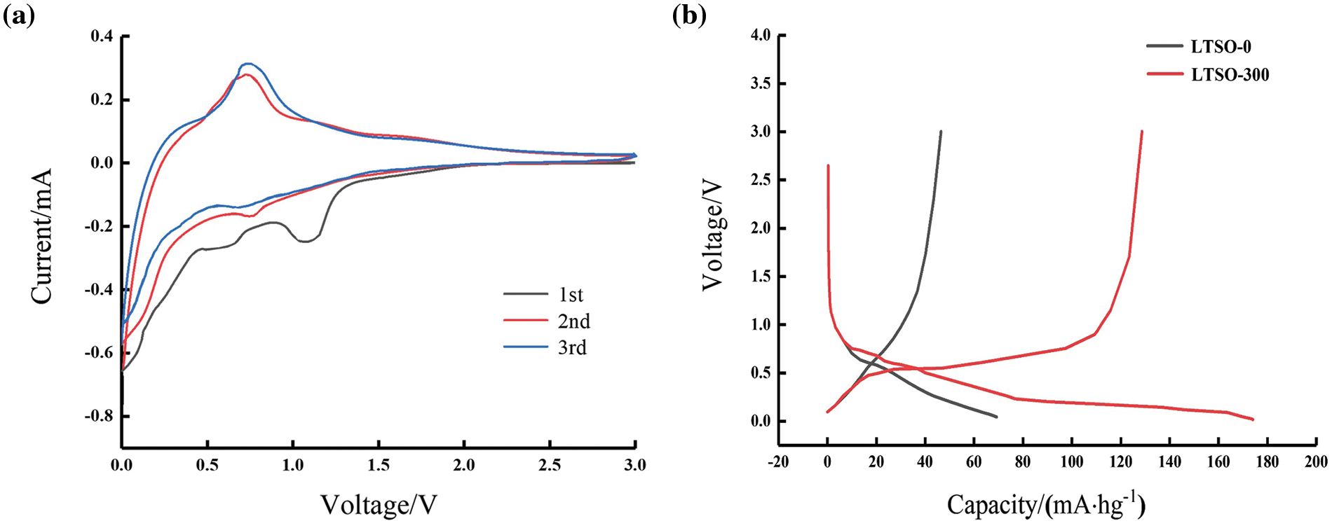
Figure 3: (a) CV curves of LTSO-0 at 0.1 Ag−1 for the first three cycles; (b) charge/discharge curves of LTSO-0 and LTSO-300 at 0.1 Ag−1 for the first cycle of LTSO-0 and LTSO-300
Fig. 3b delineates the maiden charge-discharge curves of LTSO-0 and LTSO-300 at 0.1 Ag−1. LTSO-0 evinces a steeper voltage curve slope and a swifter capacity decay, with the initial coulombic efficiency standing at 58.1%. Conversely, LTSO-300 displays discernible discharge and charge plateaus around 0.25 and 0.75 V, respectively, accompanied by an initial coulombic efficiency of 74.7%. The elevated reversible capacity is ascribed to the augmentation in specific surface area and the acceleration of electron/ion migration rates, engendered by plasma bombardment.
Fig. 4a depicts the cycle performance of LTSO-0 and LTSO-300 at 0.1 Ag−1. The initial discharge capacity of pristine LTSO-0 stands at 69.2 mA·hg−1, declining to 54.4 mA·hg−1 after 500 cycles, yielding a capacity retention of 78.6%. Conversely, LTSO-300 showcases an initial discharge capacity of 174.1 mA·hg−1. Following 500 cycles, its capacity diminishes to 144.7 mA·hg−1, maintaining a capacity retention of 83.1%. Notably, LTSO-300 exhibits an initial cycling ramp, indicative of an electrochemical activation process. The heightened initial capacity and retention rate of LTSO-300 are ascribed to the effective augmentation of lithium storage sites and diffusion kinetics facilitated by oxygen vacancies generated via plasma sputtering.
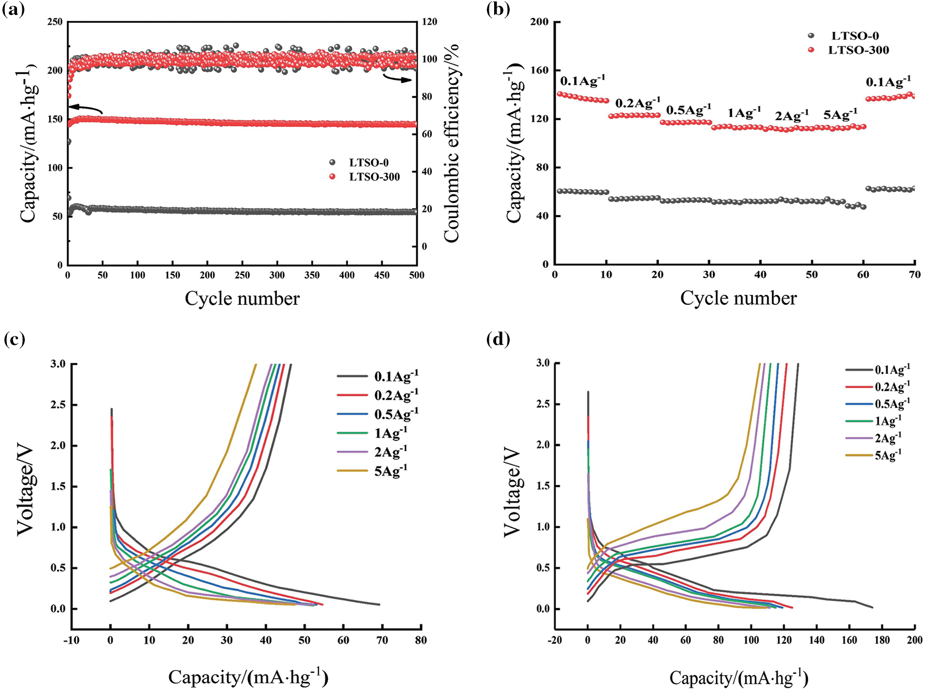
Figure 4: Electrochemical performance of LTSO-0 and LTOS-300: (a) cycling curves at 0.1 Ag−1; (b) rate performance; (c and d) charge/discharge curves at 0.1 Ag−1 of LTSO-0 and LTSO-300
Fig. 4b delineates the rate performance of LTSO-0 and LTSO-300. The reversible capacities of LTSO-0 at 0.1, 0.2, 0.5, 1, 2, and 5 Ag−1 are 60.1, 54.7, 53.2, 51.2, 51.9, and 47.7 mA·hg−1, respectively, significantly surpassing those of LTSO-0. Even at a current density of 0.1 Ag−1, the reversible capacity of LTSO-300 remains at 137.6 mA·hg−1, evincing its high reversibility and adeptness in adapting to different current densities. Figs. 4c and 4d portrays the charge-discharge curves of LTSO-0 and LTSO-300 at various rates. The voltage plateaus of both LTSO-0 and LTSO-300 lie within the 0~1 V range, aligning with the outcomes of the CV curves. Conversely, the discharge curves of LTSO-300 exhibit relatively denser plateaus compared to LTSO-0, with distinct voltage plateaus even at 5 Ag−1, signifying an improvement in the electrochemical reaction kinetics of LTSO-300.
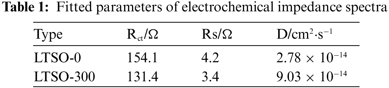
Electrochemical impedance spectroscopy (EIS) is conducted to assess the performance enhancement mechanism of LTSO-0 and LTSO-300. In Fig. 5a, all samples portray semicircles intricately correlated with charge transfer resistance, while the straight lines in the low-frequency spectrum reflect the lithium-ion diffusion kinetics of the materials. Fitting with the equivalent circuit in the inset unveils that the intrinsic resistance (Rs) of LTSO-0 and LTSO-300 dwindles from 4.2 to 2.8 Ω with escalating plasma power, signifying an augmentation in electronic conductivity post-plasma treatment. Additionally, LTSO-300 evinces the lowest charge transfer resistance (131.4 Ω) compared to LTSO-0. Lithium-ion diffusion coefficients (D) are computed utilizing Equations to evaluate their ion diffusion capabilities. The lithium-ion diffusion coefficient (D) was calculated according to Eqs.(1) and (2) to evaluate its ion diffusion capability.
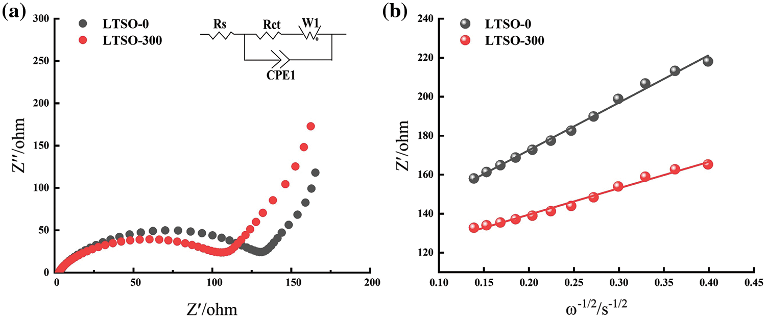
Figure 5: Electrochemical impedance spectra and data of LTSO-0 (a) and LTSO-300 (b)
where R represents the gas constant, Jmol−1K−1; A represents the electrode surface area, cm2; T represents the thermodynamic temperature, °C; n represents the number of electrons; F represents the Faraday constant, C·mol−1; C represents the lithium-ion concentration, mol·L−1. The slope
This investigation illuminates the surface modification of LTSO utilizing clean and environmentally benign plasma treatment. Morphological and structural scrutiny unveils that plasma treatment can heighten the degree of dispersion and potentially introduce defects such as oxygen vacancies. Electrochemical behavior characterization delineates that plasma sputtering can optimize the intrinsic electronic/ion conductivity of LTSO, thereby enhancing its reversible capacity, cycling stability, and diffusion kinetics. Among these, LTSO-300 emerges as the epitome of electrochemical performance, showcasing a capacity of 144.7 mA·hg−1 post-500 cycles at 0.1 Ag−1, with a capacity retention rate of 83.1%.
Acknowledgement: None.
Funding Statement: This research is supported by Changzhou Basic Research Program (No. CJ20235030) and the Research Initiation Fund of Changzhou University (No. ZMF23020057).
Author Contributions: The authors confirm contribution to the paper as follows: study conception and design: Yunfeng Deng and Qifeng Qian; analysis and interpretation of results: Lingchao Xiao and Shangqi Sun; draft manuscript preparation: Shangqi Sun. All authors reviewed the results and approved the final version of the manuscript.
Availability of Data and Materials: Data supporting this study are included within the article.
Ethics Approval: Not applicable.
Conflicts of Interest: The authors declare that they have no conflicts of interest to report regarding the present study.
References
1. Y.-M. Wei, K. Chen, J.-N. Kang, W. Chen, X. Zhang and X.-Y. Wang, “Policy and management of carbon peaking and carbon neutrality: A literature review,” Engineering, vol. 14, no. 2, pp. 52–63, 2022. doi: 10.1016/j.eng.2021.12.018. [Google Scholar] [CrossRef]
2. Y. Shi et al., “Ultra-high rate capability of in-situ anchoring FeF3 cathode onto double-enhanced conductive Fe/graphitic carbon for high energy density lithium-ion batteries,” Nano Energy, vol. 108, pp. 108181, 2023. doi: 10.1016/j.nanoen.2023.108181. [Google Scholar] [CrossRef]
3. L. Zhao et al., “Revisiting the roles of natural graphite in ongoing lithium-ion batteries,” Adv. Mater., vol. 34, no. 18, pp. 2106704, 2022. doi: 10.1002/adma.202106704. [Google Scholar] [PubMed] [CrossRef]
4. Z. Huang, P. Luo, H. Zheng, and Z. Lyu, “Sulfur-doped graphene promoted Li4Ti5O12@C nanocrystals for lithium-ion batteries,” J. Alloys Comp., vol. 908, pp. 164599, 2022. doi: 10.1016/j.jallcom.2022.164599. [Google Scholar] [CrossRef]
5. L. Jin et al., “Toward high energy-density and long cycling-lifespan lithium ion capacitors: A 3D carbon modified low-potential Li2TiSiO5 anode coupled with a lignin-derived activated carbon cathode,” J. Mater. Chem. A, vol. 7, no. 14, pp. 8234–8244, 2019. doi: 10.1039/c8ta12000e. [Google Scholar] [CrossRef]
6. J. Liu et al., “Li2TiSiO5: A low potential and large capacity Ti-based anode material for Li-ion batteries,” Energy Environ. Sci., vol. 10, no. 6, pp. 1456–1464, 2017. doi: 10.1039/c7ee00763a. [Google Scholar] [CrossRef]
7. D. Su et al., “Electrospun Na doped Li2TiSiO5/C nanofibers with outstanding lithium-storage performance,” Appl. Surf. Sci., vol. 541, pp. 148388, 2021. doi: 10.1016/j.apsusc.2020.148388. [Google Scholar] [CrossRef]
8. S. Wang, R. Wang, Y. Bian, D. Jin, Y. Zhang and L. Zhang, “In-situ encapsulation of pseudocapacitive Li2TiSiO5 nanoparticles into fibrous carbon framework for ultrafast and stable lithium storage,” Nano Energy, vol. 55, pp. 173–181, 2019. doi: 10.1016/j.nanoen.2018.10.052. [Google Scholar] [CrossRef]
9. Y. Mei et al., “Lithium-ion insertion kinetics of Na-doped Li2TiSiO5 as anode materials for lithium-ion batteries,” J. Mater. Sci. Technol., vol. 57, pp. 18–25, 2020. doi: 10.1016/j.jmst.2020.05.012. [Google Scholar] [CrossRef]
10. Z. Wang et al., “Plasma-enabled synthesis and modification of advanced materials for electrochemical energy storage,” Energy Storage Mater., vol. 50, no. 21, pp. 161–185, 2022. doi: 10.1016/j.ensm.2022.05.018. [Google Scholar] [CrossRef]
11. Y. Wu et al., “Tuning original anion defects for Co3O4 to promote heteroatom doping with different valences for enhanced lithium storage,” Appl. Surf. Sci., vol. 623, no. 1, pp. 157047, 2023. doi: 10.1016/j.apsusc.2023.157047. [Google Scholar] [CrossRef]
12. Y. Chen et al., “Gradient nitrogen doping in the garnet electrolyte for highly efficient solid-state-electrolyte/li interface by N2 plasma,” ACS Appl. Mater. Interfaces, vol. 15, no. 38, pp. 44962–44973, 2023. doi: 10.1021/acsami.3c09154. [Google Scholar] [PubMed] [CrossRef]
13. R. Zhou et al., “Plasma-electrified up-carbonization for low-carbon clean energy,” Carbon Energy, vol. 5, no. 1, pp. e260, 2023. doi: 10.1002/cey2.260. [Google Scholar] [CrossRef]
14. Y. Li, Y. Mei, X. Lan, Y. Jiang, and X. Hu, “Insight into effects of niobium on electrospun Li2TiSiO5 fibers as anode materials in lithium-ion batteries,” Mater. Res. Bull., vol. 136, pp. 111145, 2021. doi: 10.1016/j.materresbull.2020.111145. [Google Scholar] [CrossRef]
15. S. Liu, W. Tang, J. Ma, Y. Zhang, and Y. Yue, “Li2TiSiO5 glass ceramic as anode materials for high-performance lithium-ion batteries,” ACS Appl. Energy Mater., vol. 3, no. 10, pp. 9760–9768, 2020. doi: 10.1021/acsaem.0c01357. [Google Scholar] [CrossRef]
16. Q. Song, S. Zhou, S. Wang, S. Li, L. Xu and J. Qiu, “Insights into the oxygen vacancies in transition metal oxides for aqueous Zinc-Ion batteries,” Chem. Eng. J., vol. 461, no. 30, pp. 142033, 2023. doi: 10.1016/j.cej.2023.142033. [Google Scholar] [CrossRef]
17. Y. Liu et al., “One-pot synthesis of soft carbon-combined Li2TiSiO5 composites with oxygen vacancies as long life and high rate anodes for lithium-ion batteries,” Electrochim. Acta, vol. 387, pp. 138469, 2021. doi: 10.1016/j.electacta.2021.138469. [Google Scholar] [CrossRef]
Cite This Article
 Copyright © 2024 The Author(s). Published by Tech Science Press.
This work is licensed under a Creative Commons Attribution 4.0 International License , which permits unrestricted use, distribution, and reproduction in any medium, provided the original work is properly cited.
 Downloads
 Citation Tools