
 Submit a Paper
 Propose a Special lssue
 Open Access
ARTICLE

Optimal Design and Experimental Study of Tightly Coupled SCR Mixers for Diesel Engines
1 State Key Laboratory of Engines, Tianjin Univesity, Tianjin, 300072, China
2 Weichai Power Emission Solutions Technology Co., Ltd., Weifang, 261061, China
3 School of Energy and Power Engineering, Shandong University, Jinan, 250061, China
* Corresponding Author: Zhijun Li. Email:
Energy Engineering 2024, 121(10), 2893-2906. https://doi.org/10.32604/ee.2024.051093
Received 27 February 2024; Accepted 13 May 2024; Issue published 11 September 2024
 View Full Text
 Download PDF
Abstract
Two types of tightly coupled Selective Catalytic Reduction (SCR) mixers were designed in this study, namely Mixer 1 integrated with an SCR catalyst and Mixer 2 arranged separately. Computational Fluid Dynamics (CFD) software was utilized to model the gas flow, spraying, and pyrolysis reaction of the aqueous urea solution in the tightly coupled SCR system. The parameters of gas flow velocity uniformity and ammonia distribution uniformity were simulated and calculated for both Mixer 1 and Mixer 2 in the tightly coupled SCR system to compare their advantages and disadvantages. The simulation results indicated that Mixer 1 exhibited a gas velocity uniformity of 0.972 and an ammonia distribution uniformity of 0.817, whereas Mixer 2 demonstrated a gas velocity uniformity of 0.988 and an ammonia distribution uniformity of 0.964. Mixer 2 performed better in the simulation analysis. Furthermore, a 3D-printed prototype of Mixer 2 was manufactured and installed on an engine test bench to investigate ammonia distribution uniformity and NOX conversion efficiency. The experimental investigations yielded the following findings: 1) The ammonia distribution uniformity of Mixer 2 was measured as 0.976, which closely aligned with the simulation result of 0.964, with a deviation of 1.2% from the model calculations; 2) As exhaust temperature increased, the ammonia distribution uniformity gradually improved, while an increase in exhaust flow rate resulted in a decrease in ammonia distribution uniformity; 3) When utilizing Mixer 2, the NOX conversion efficiency reached 84.7% at an exhaust temperature of 200°C and 97.4% at 250°C. Within the exhaust temperature range of 300°C to 450°C, the NOX conversion efficiency remained above 98%. This study proposed two innovative mixer structures, conducted simulation analysis, and performed performance testing. The research outcomes indicated that the separately arranged Mixer 2 exhibited superior performance. The tightly coupled SCR system equipped with Mixer 2 achieved excellent levels of gas velocity uniformity, ammonia distribution uniformity, and NOX conversion efficiency. These findings can serve as valuable references for the design and development of ultra-low emission after-treatment systems for diesel engines in the field of diesel engine aftertreatment.Keywords
Today’s environmental problems are becoming increasingly serious, and improving air quality is a challenge for many countries, and in the context of “carbon peaking and carbon neutrality”, reducing diesel exhaust pollutant emissions is still of great importance [1,2]. Automobiles are the main component of mobile source pollutant emissions, accounting for more than 90% of NOX emissions, with diesel vehicles accounting for 88.9% of NOX emissions from automobiles [3]. To control the emissions of diesel vehicles, countries have established strict emission regulations [4], and to cope with the increasingly stringent emission regulations, diesel emission control technologies have been rapidly developed in recent years, among which SCR technology has become the preferred technological solution to reduce NOX emissions from diesel engines [5]. The mixer in the SCR system has a great influence on the evaporation, decomposition, and mixing of urea solution [6,7]. The influence is especially significant at lower exhaust temperatures. The mixer not only allows the urea spray droplets to mix more fully with the exhaust gas and improves the mixing uniformity, but also accelerates the evaporation of urea droplets, promotes the decomposition of urea, and improves the NOX conversion efficiency [8].
On 10 November 2022, the European Commission published the latest Euro 7 proposal, which proposed more stringent emission limit standards for NOX emissions from heavy-duty diesel vehicles [9], from Euro 7 onwards NOX emissions are no longer weighted for cold and hot cycles, the cold cycle emission limit is 350 mg/kWh and the hot cycle limit is 0.09 g/kWh. To meet the ultra-low emission requirements of diesel engines, the concept of an SCR dual injection system was proposed [10,11]. The SCR dual injection system has two stages of SCR, the first stage SCR is installed upstream of the Diesel Oxidation Catalyst (DOC), and the second stage SCR is installed downstream of the Diesel Particulate Filter (DPF), forming a dual injection system architecture of Close-Coupled Selective Catalytic Reduction (CCSCR)+DOC+DPF+SCR.
In order to meet the ultra-low emission NOX limits for diesel engines, the industry has conducted research work in two areas: fuel and after-treatment. In the field of fuel, Ertugrul et al. conducted engine experiments to investigate the impact of different fuel blends on nitrogen oxide (NOX) emissions. They plotted and analyzed the relevant data to understand the effects of thermal barrier coatings. Their objective was to utilize the COMSOL program for physics-based modeling of internal combustion engines in order to analyze and reduce NOX emissions [12]. Additionally, the research by Demir et al. discovered that adding urea to diesel fuel can reduce emissions of carbon dioxide and hydrocarbons, with a maximum reduction of 19% in nitrogen oxide emissions [13].
In terms of after-treatment, the primary approach employed is the use of SCR dual-injection systems to reduce nitrogen oxide emissions. Sharp et al. conducted a pilot study on a 12.4 L heavy-duty diesel engine with ultra-low emissions [14]. They proposed a configuration utilizing tightly coupled SCR, which provides valuable insights. The research findings demonstrated that compared to the traditional Euro VI technology scheme of DOC+DPF+SCR, by using an additional stage before the DOC In the FTP emission cycle, the NOX conversion efficiency reached 99.3%, and the emission was as low as 0.063 g/kWh. Zavala et al. conducted an ultra-low emission technology study on a Cummins 15 L heavy-duty diesel engine [15], and the results showed that the diesel engine ultra-low emission after-treatment system with SCR dual injection, electrically heated nozzle technology and low-temperature SCR catalyst could significantly improve the NOX conversion efficiency at low temperatures, and the FTP cycle NOX conversion efficiency reached 99.5%, and the emission is as low as 0.018 g/kWh. Liu et al. conducted a study on ultra-low emission technology on a 13 L engine [16–18], and the results showed that the after-treatment system can reach 99.3% NOX conversion efficiency by using SCR dual injection technology, and the FTP cycle cold and hot weighted emission reached 0.019 g/kWh.
The research analysis of the aforementioned literature indicates that SCR dual injection systems are the most promising aftertreatment systems for achieving ultra-low emissions in diesel engines. Among them, the tightly coupled SCR system, serving as the first-stage SCR in the SCR dual-injection system, has become a focal point in current research on diesel engine aftertreatment technologies. However, there is a lack of dedicated studies on the tightly coupled mixer in the existing research. This study effectively fills this research gap by conducting a comprehensive investigation of two different configurations of tightly coupled mixers. The findings provide valuable references for the research on tightly coupled SCR systems and the design of SCR dual injection aftertreatment systems.
To utilize the heat of diesel exhaust gas as much as possible, the tightly coupled SCR system is arranged behind the diesel engine supercharger, which has high requirements for performance and installation arrangement [18], firstly, the ammonia distribution uniformity is more than 0.95, SCR conversion efficiency is higher than 80% at 200°C, and the mixer back pressure is less than 3 kpa, secondly, the tightly coupled SCR mixer is required to be as compact as possible in structure and easy to installation arrangement.
Based on the above requirements, two types of mixers were designed. The schematic diagram of the mixer is shown in Fig. 1. Mixer 1 consists of a nozzle mount, cyclone plate, spray droplet crushing network and outer cylinder, the back can be directly connected with the SCR catalyst; urea spray perpendicular to the direction of gas flow, exhaust gas flow through the cyclone plate will produce the effect of the cyclone, strengthen gas disturbance, conducive to the breaking of urea spray droplets, accelerate the full mixing of urea and airflow. At the same time, the spray droplet crushing network can effectively improve the secondary crushing effect of urea spray and accelerate the decomposition of urea. Mixer 2 is designed with a 90° bend angle, including the nozzle mount, turbine blade, and insulation shell, nozzle mount is arranged at a 90° bend, urea spray direction, and exhaust airflow flow direction, exhaust airflow will produce a strong cyclonic effect when flowing through the turbine blade, making the airflow in the spray area produce strong disturbance to strengthen the mixing effect of spray and exhaust. At the same time, the turbine blades increase the contact area between the urea spray and the mixer, which can accelerate the decomposition of urea, while Mixer 2 is very compact in structure and easy to install and arrange. Due to its complex structure, the fabrication of Mixer 2 samples employed a 3D printing technique, utilizing 436 stainless steel material known for its urea-resistant properties.
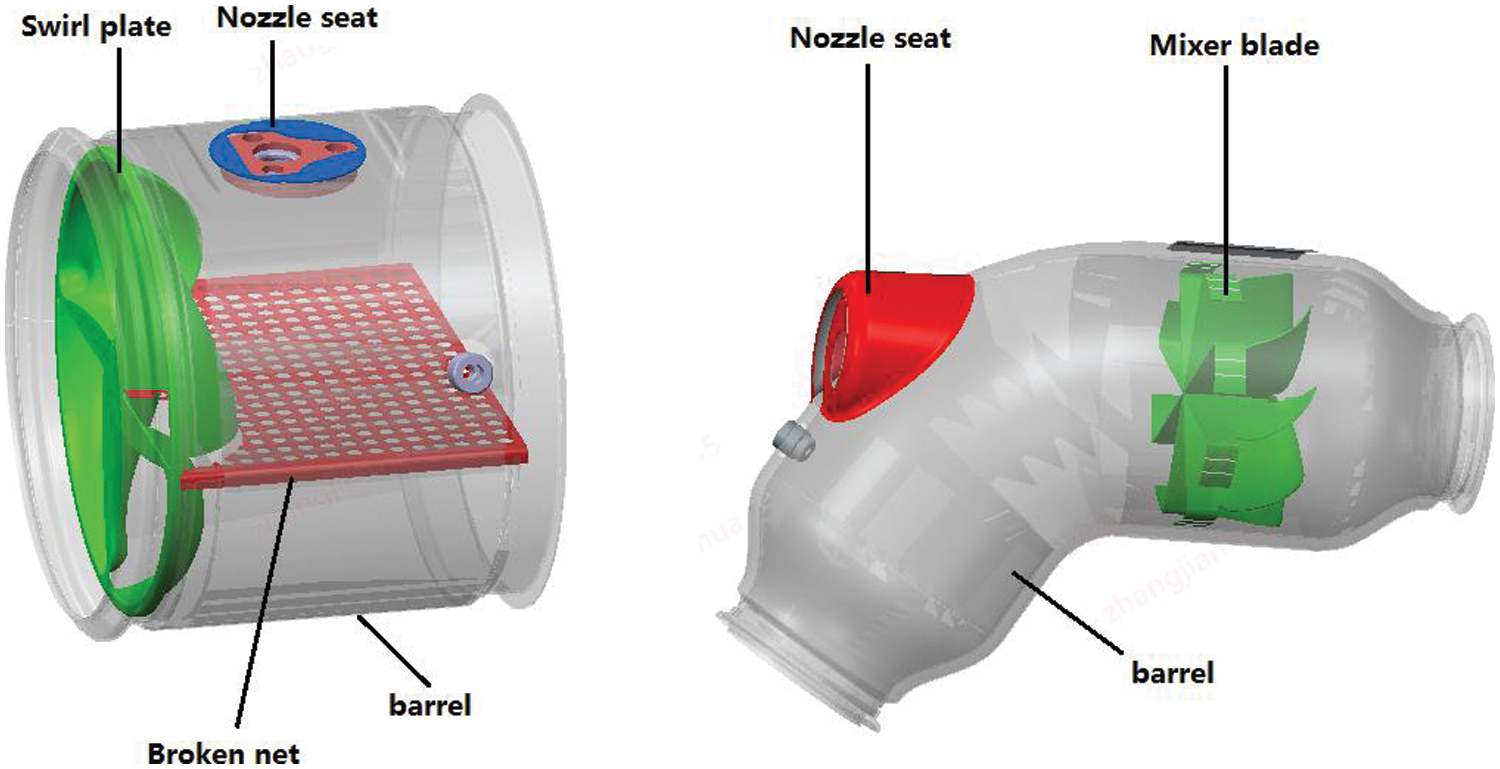
Figure 1: Two types of tightly coupled SCR mixer
3 Equations and Mathematical Expressions
3.1 Velocity Uniformity Simulation Analysis
Velocity uniformity is a uniformity parameter of the exhaust gas through the catalyst cross-section, which represents the level of airflow uniformity when the exhaust gas is in contact with the catalyst. The 2 mixer structures in Fig. 1 were modeled in 3D and meshed by Hypermesh V13.0 for the numerical model, as shown in Fig. 2.
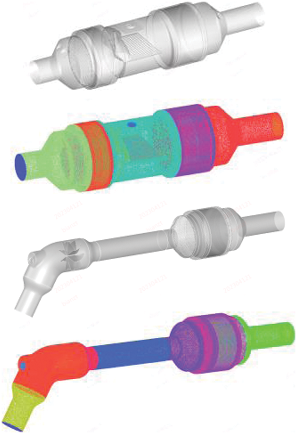
Figure 2: Tightly coupled SCR system model and meshing
To verify the insensitivity of the computed results to the grid quantity, we selected the pressure drop across the entire fluid domain as the validation indicator. While keeping the boundary layer grid parameters unchanged, we adjusted the global base grid size to achieve grid quantities of 3, 4, and 5 million, respectively. The corresponding pressure drops were found to be 8.22, 8.48, and 8.43 kPa. These results indicate that the pressure drop is no longer sensitive to the grid quantity.
Fluent was used to calculate the airflow velocity uniformity at the front face of the tightly coupled SCR catalyst, and the results are shown in Fig. 3. The comparison shows that the airflow velocity uniformity at the front face of the SCR catalyst in the tightly coupled aftertreatment system with Mixer 1 is 0.972, whereas it is 0.988 in the tightly coupled aftertreatment system with Mixer 2. It can be observed that Mixer 2 exhibits better airflow velocity uniformity.
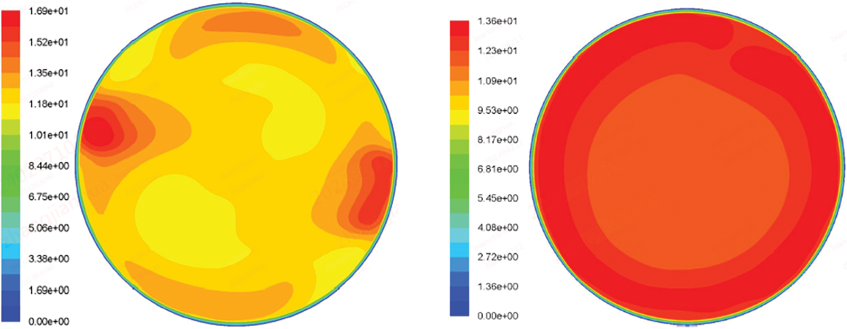
Figure 3: Airflow velocity uniformity (The units in the figure are m/s)
After the urea spray is sprayed into the mixer, it is fully mixed with the exhaust gas in the pipeline and pyrolyzed to NH3 under the effect of the mixer, and the mixed gas with NH3 flows to the front face of the catalyst, where NH3 reacts with NOX in the exhaust gas to form N2 and H2O, so the uniformity of ammonia distribution on the front face of the catalyst is of vital importance for the catalytic reaction of the catalyst.
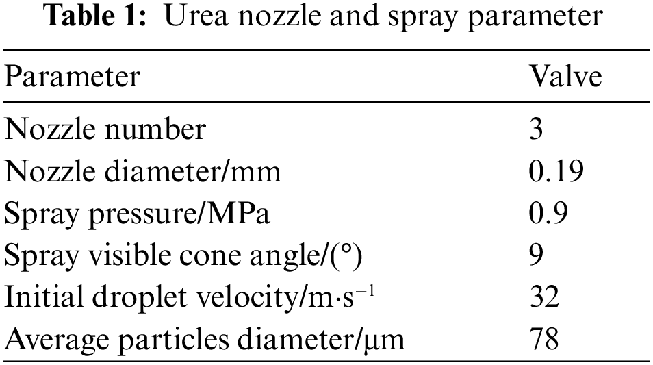
The SCR after-treatment system uses a Bosch non-gas-assisted urea injection system, Table 1 shows the relevant parameters of the urea nozzle, and the CFD simulation uses a discrete phase model (DPM) to simulate the spray motion [18], which is established according to the Euler-Lagrange method and treats the fluid as a continuous medium to solve the N-S equation; the spray droplets are treated as a discrete medium that can exchange mass, momentum, and energy with the fluid by tracing the trajectory of a large number of particles to solve.
The simulation was carried out for the common operating conditions of a 10 L engine, with the exhaust mass flow rate set to 900 kg/h, the inlet exhaust temperature set to 450°C, and the urea injection volume of 245 mg/s, corresponding to an engine operating condition of 1500 rpm and 1200 Nm of torque. The simulation process was carried out by first calculating the steady-state internal flow field until the flow field was fully converged, and then adding urea injection to calculate the development of urea spray and ammonia distribution in a transient solution.
Fig. 4 shows the results of comparing the uniformity of ammonia distribution on the front face of the SCR catalyst-equipped with 2 mixers. From the figure, it can be seen that the ammonia distribution uniformity coefficient of the after-treatment system with Mixer 1 installed is lower at 0.817, while the ammonia distribution uniformity coefficient of the after-treatment system with Mixer 2 is 0.964, and the simulation result of Mixer 2 is more excellent.
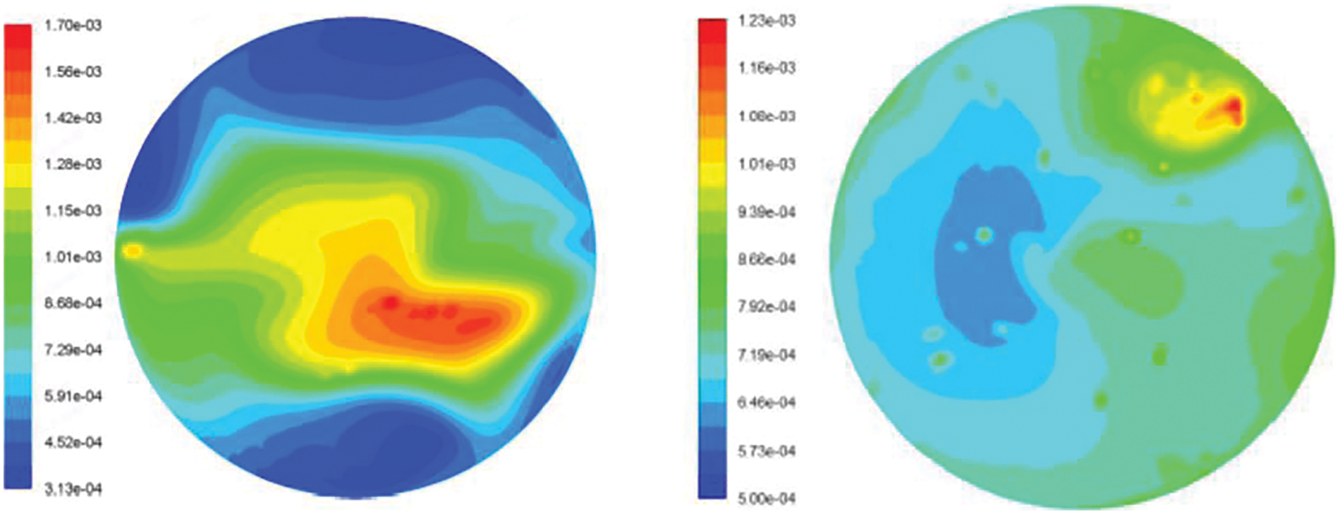
Figure 4: Distribution uniformity simulation analysis result of two mixers (The number shown in the figure is the mass fraction)
The urea spray trajectory refers to the movement trajectory of urea droplet particles after being sprayed from the nozzle, which is affected by the engine exhaust gas flow, mixer structure, and the performance of the urea nozzle itself, and can reflect the heat evaporation of urea droplet particles, which further reflects the concentration distribution of ammonia gas. As shown in Fig. 5, it can be seen from the spray trajectory that the spray trajectory of Mixer 1 is more concentrated, and after passing through the droplet breaking network most of the spray is sprayed to the bottom wall and bounced back, and the distribution of urea on the front surface of SCR catalyst is not uniform enough, while the spray trajectory of mixer 2 accelerates the rotation under the action of turbo mixer, and the distribution on the front surface of SCR catalyst is more uniform.
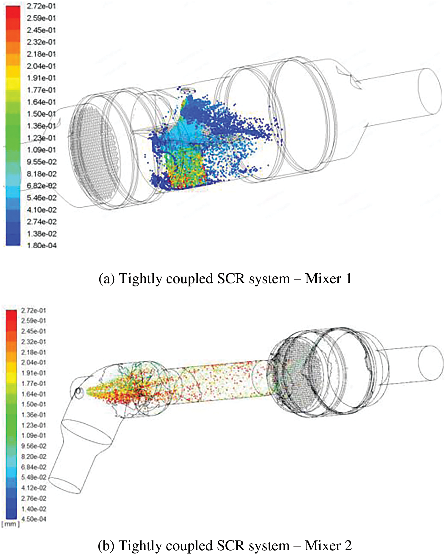
Figure 5: Urea spray trajectory of 2 mixers (The units in the figure are mm)
4 Equations and Mathematical Expressions
The CFD method was used to analyze the airflow velocity uniformity, ammonia distribution uniformity, and urea spray trajectory on the front surface of the SCR catalyst of two different tightly coupled SCR mixers of the after-treatment system. The simulation results showed that the performance of Mixer 2 was superior, and the performance test study of Mixer 2 was conducted using an engine bench test. The test platform included the engine, SCR after-treatment system, dynamometer and control system, engine fuel supply, and fuel consumption measurement system, multi-component emission analyzer, and ammonia distribution uniformity test analyzer. Table 2 shows the basic parameters of the engine, Table 3 shows the test instruments and meters, and Fig. 6 shows the engine bench arrangement and ammonia distribution uniformity test setup. The experiment employed a commercial urea aqueous solution, conforming to the national standard “GB 29518-2013 Diesel Engine Nitrogen Oxide Reductant Urea Aqueous Solution (AUS32).” The concentration of urea in the solution was 32.5%. The urea aqueous solution readily decomposes into NH3 when heated, serving as a reducing agent for the chemical reaction with NOX in the exhaust. The exhaust flow rate was determined by calculating the intake flow rate and fuel consumption. The intake flow rate was measured using an intake flow meter installed in the intake duct of the test bench, while fuel consumption was measured using a fuel consumption meter. A Sensata company PT200 specification temperature sensor was utilized for measuring exhaust temperature, with a range of −40°C to 800°C. The urea injection system employed the Bosch company’s DeNOX2.2 urea injection system. Detailed information regarding these sensors and the urea injection system can be found in Table 3.
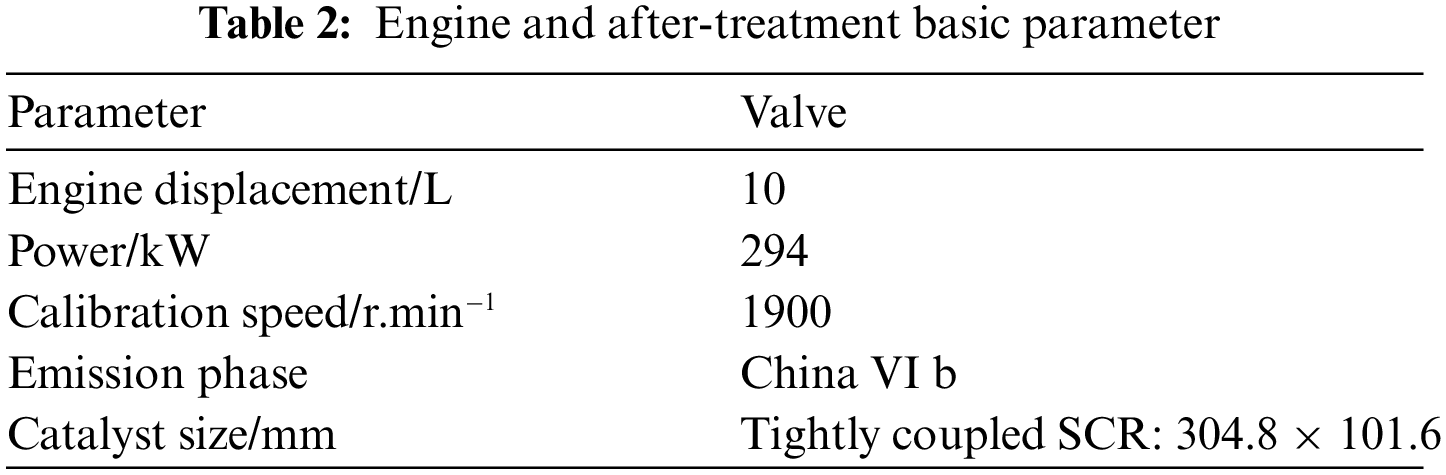
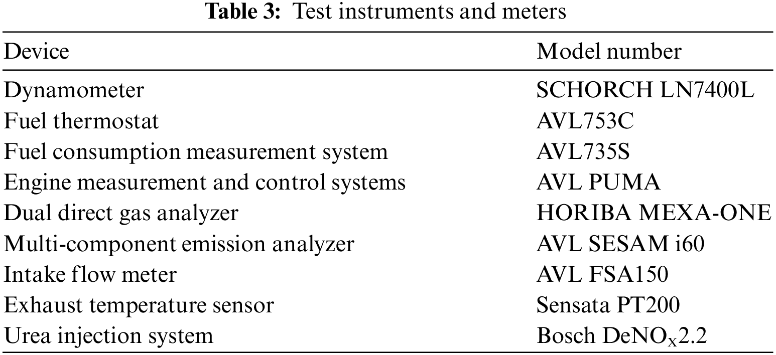
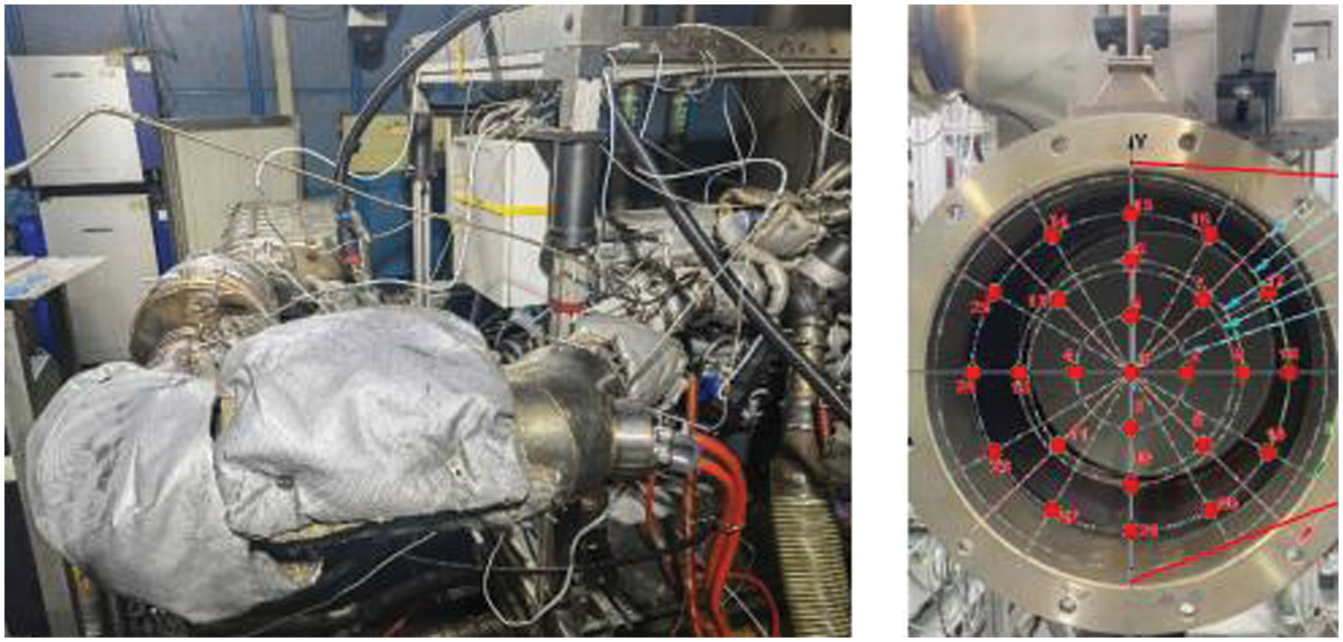
Figure 6: Bench arrangement and ammonia distribution uniformity testing device
4.2.1 Ammonia Distribution Uniformity Test
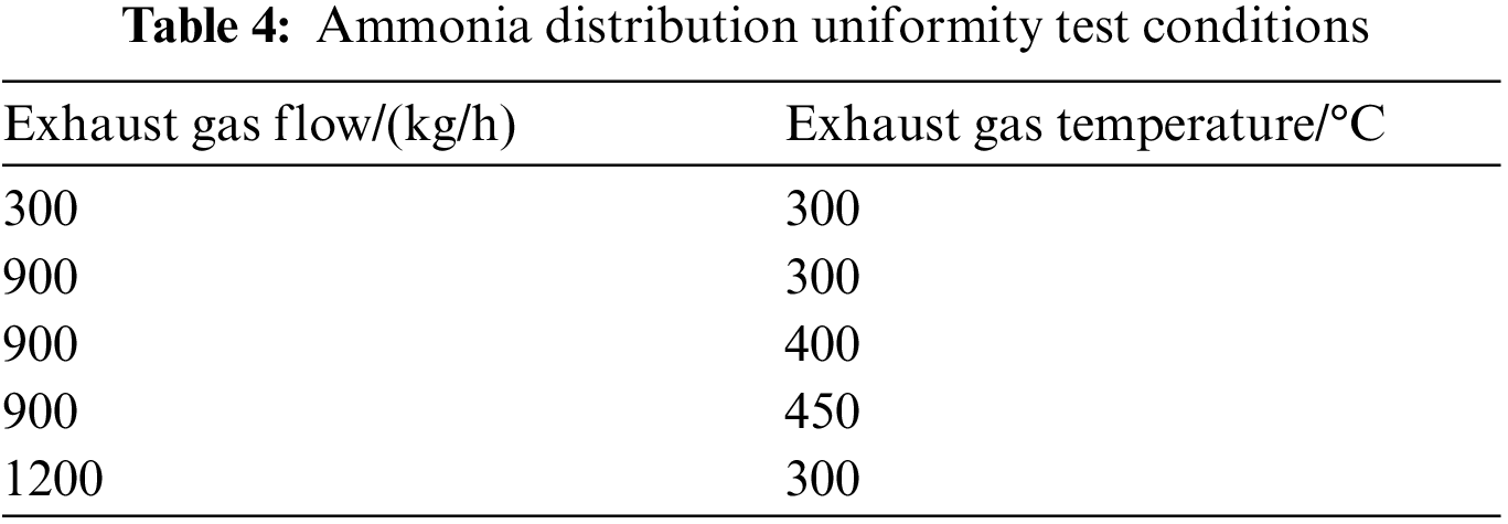
The real ammonia uniformity data can be obtained by testing the ammonia concentration distribution on the front face of the SCR. The ammonia distribution uniformity was measured using the special equipment in Fig. 6. The test was conducted by adjusting the engine exhaust flow and exhaust temperature to stabilize the operating conditions at each operating point given in Table 4, and the urea injection volume was determined according to the NOX emission level at each operating condition, and urea injection was conducted according to ANR = 0.7. The ammonia distribution uniformity test needs to cut the end face of the after-treatment system, the FTIR measurement probe penetrates deep into the end face set position to measure the concentration of NH3 in the airflow during the test and then moves to the next position point test after completing the test at one position point until the data test is completed for all 25 position points.
4.2.2 Ammonia Distribution Uniformity Test
The most important role of the tightly coupled SCR mixer is to ensure the NOX conversion efficiency of the system, the test condition points are shown in Table 5.
Control the engine speed and torque to make the temperature and exhaust flow rate upstream of SCR reach the set value, record the NOX concentration value upstream of SCR after the working condition is stabilized, set the ammonia to nitrogen ratio to 1.2, record the NOX concentration at this working condition point after the SCR catalyst is stabilized, each working condition point before starting the test by running at the high-temperature working condition point and stop injecting urea until the NOX concentration before and after the SCR catalyst is stable and essentially the same.
5.1 Ammonia Distribution Uniformity Analysis
The uniformity index
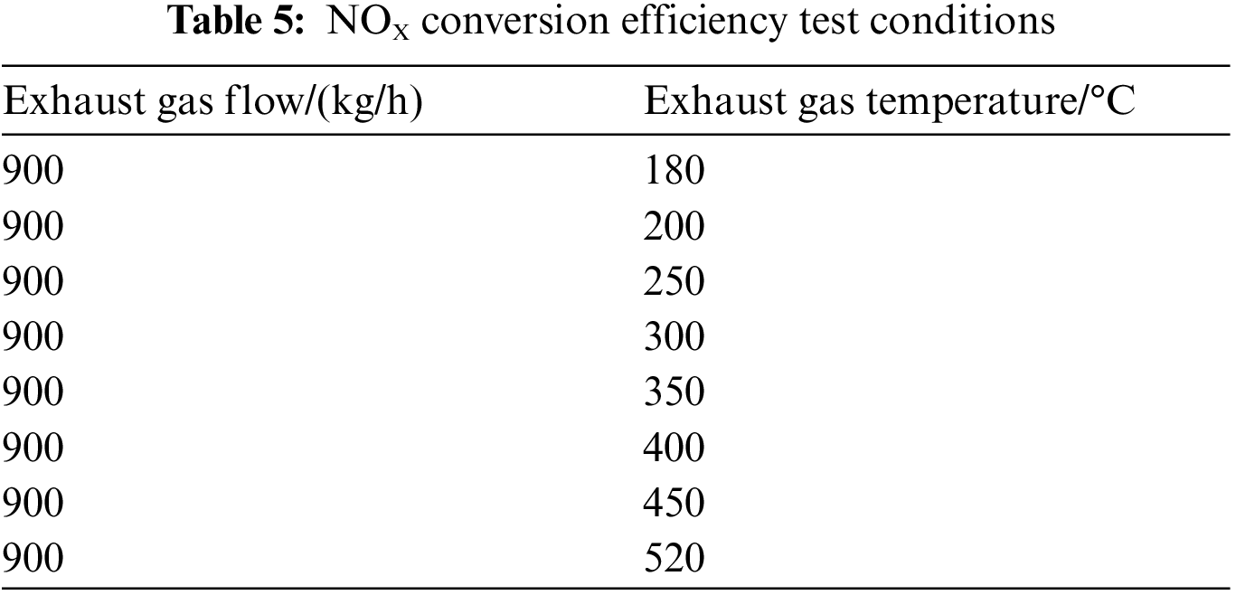
In this formula: n is the number of measurement points of the cross-section; i is the NH3 concentration of the measurement point; c is the average NH3 concentration on the whole cross-section. γ is larger and closer to 1, which means it the more uniform on the selected cross-section. The results of the uniformity index of ammonia distribution on the front surface of the SCR catalyst obtained from the test under different working conditions are shown in the figure below. It can be seen from the figure that the uniformity index of ammonia distribution at 900 kg/h, 450°C is 0.976, which is close to the result of 0.964 calculated by simulation, and the deviation between the test and simulation is 1.2%. Considering the limited number of test spots, the accuracy of a simulation model is high. In addition to verifying the calculation accuracy of the simulation model, the effects of exhaust flow rate and exhaust temperature on the uniformity of ammonia distribution were also studied separately, as shown in Fig. 7, and the results showed that: in the range of 300°C–450°C, the uniformity of ammonia distribution gradually increased with the increase of exhaust temperature, and the increase rate was faster in the range of 300°C–400°C. When the temperature exceeded 400°C, the uniformity of ammonia distribution increased slowly and the change was smaller. When the temperature exceeds 400°C, the uniformity of ammonia distribution increases slowly and the change is small; under the condition that the exhaust temperature is 300°C, the uniformity of ammonia distribution decreases gradually with the increase of exhaust flow. The ammonia distribution uniformity test results show that the ammonia distribution uniformity index is different under different exhaust temperatures and exhaust flow conditions, and the ammonia distribution uniformity index is influenced by the exhaust temperature and exhaust flow.
Figure 7: Variation of ammonia distribution uniformity with exhaust temperature and exhaust flow rate
5.2 Analysis of Tightly Coupled SCR Conversion Efficiency
The copper-based catalyst was selected for the tightly coupled SCR system, catalyst specifications are shown in Table 6. The steady-state NOX conversion efficiency of the tightly coupled SCR system was tested on the engine bench, and the results are shown in Fig. 8, which shows that the NOX conversion efficiency of the after-treatment system reached 84.7% at 200°C, and 250°C reached 94.7%, the conversion efficiency of the catalyst at high temperature did not drop, the highest temperature tested was 520°C, the NOX conversion efficiency was 98.8%, which proved that the performance of the mixer and the tightly coupled SCR system was excellent and reached the design index of the system.
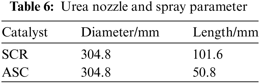
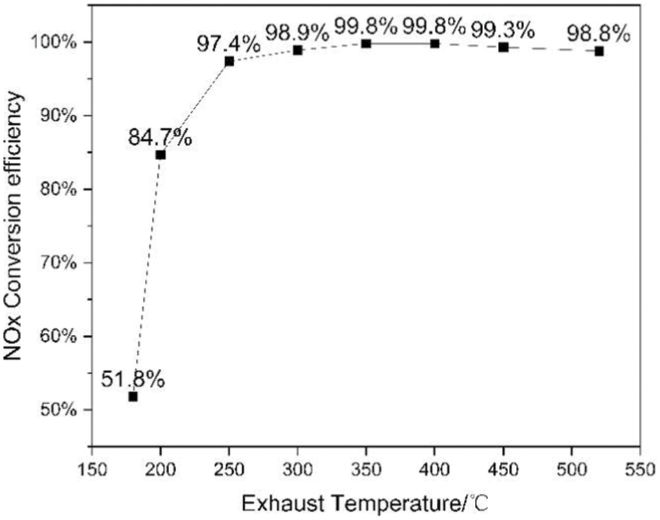
Figure 8: Steady-state NOX conversion efficiency of tightly coupled SCR systems
The implementation of Euro 7 and other stringent emission regulations has significantly stimulated the research and development of closely-coupled Selective Catalytic Reduction (SCR) technology. This study is dedicated to examining the design and performance of closely-coupled SCR mixers. The key findings are as follows:
1. Independently arranged mixers exhibit superior performance compared to mixers integrated with SCR catalysts. Two distinct configurations of closely-coupled SCR mixers were devised, and simulation results indicate that independently arranged mixers achieved a velocity uniformity of 0.988 and an ammonia distribution uniformity of 0.964. Rigorous bench testing substantiated the model’s calculations with a deviation of merely 1.2% from the experimental results. In contrast, mixers integrated with SCR catalysts attained a velocity uniformity of 0.972 and an ammonia distribution uniformity of 0.964. The independently arranged mixers demonstrated exceptional performance.
2. As the exhaust temperature rises, the uniformity of ammonia distribution gradually improves, while an increase in exhaust flow rate leads to a gradual reduction in ammonia distribution uniformity. The bench testing results highlight that in addition to mixer structure, exhaust temperature, and flow rate are critical factors influencing ammonia distribution uniformity. Within the exhaust temperature range of 300°C–450°C, a higher temperature corresponds to an incremental enhancement in ammonia distribution uniformity. Similarly, within the exhaust flow rate range of 600–1200 kg/h, an elevated flow rate correlates with a progressive decrease in ammonia distribution uniformity.
3. Benefiting from the outstanding performance of Mixer 2, the closely-coupled SCR system achieved remarkably high NOX conversion efficiency during the test bench experiments. The test bench results reveal that, at an exhaust temperature of 200°C, the steady-state NOX conversion efficiency reached 84.7%. Furthermore, at an exhaust temperature of 250°C, the NOX conversion efficiency soared to 97.4%.
Numerous avenues for further research exist within the realm of closely-coupled SCR systems for achieving ultra-low diesel emissions. This study has merely explored a fraction of the possibilities, and future work will delve into aspects such as the durability of closely-coupled SCR systems and the characteristics associated with N2O generation.
Acknowledgement: None.
Funding Statement: The authors received no specific funding for this study.
Author Contributions: The authors confirm contribution to the paper as follows: study conception and design: Jianhua Zhang, Zhijun Li; data collection: Jianhua Zhang; analysis and interpretation of results: Jianhua Zhang; draft manuscript preparation: Wen Sun. All authors reviewed the results and approved the final version of the manuscript.
Availability of Data and Materials: The authors confirm that the data supporting the findings of this study are available within the article.
Ethics Approval: Not applicable.
Conflicts of Interest: The authors declare that they have no conflicts of interest to report regarding the present study.
References
1. Z. J. Li, Y. Wang, J. G. Wang, Z. Y. Li, B. X. Shen and Z. G. Li, “Modeling of highly loaded copper-based SSZ-13 molecular sieve catalysts for selective catalytic reduction,” (in Chinese), J. Tianjin Univ., vol. 56, no. 1, pp. 47–54, Jan. 2023. doi:10.11784/tdxbz202111012. [Google Scholar] [CrossRef]
2. A. Güthenke et al., “Current status of modeling lean exhaust gas aftertreatment catalysts,” Adv. Chem. Eng., vol. 33, no. 1, pp. 103–283, Jan. 2007. doi:10.1016/S0065-2377(07)33003-2. [Google Scholar] [CrossRef]
3. Ministry of Ecology and Environment of the People’s Republic of China, “Motor vehicle emissions situation,” in China Mobile Source Environmental Management Annual Report. Accessed: Aug. 10, 2020 [Online]. Available: http://www.mee.gov.cn [Google Scholar]
4. F. C. Barbosa, “Heavy duty diesel emission standards regulation evolution review–Current outcomes and future perspectives,” SAE Tech. Pap., vol. 1, Jan. 2020. doi:10.4271/2019-36-0174. [Google Scholar] [CrossRef]
5. D. Zhang, Q. Ma, L. Zhang, H. Ren, and Y. Yan, “Coupling research of flow field and chemical reaction in a diesel Urea-SCR system,” (in Chinese), Neiranji Gongcheng, vol. 39, pp. 59–66, Dec. 2018. doi:10.13949/j.cnki.nrjgc.2018.06.008. [Google Scholar] [CrossRef]
6. Q. Wang, D. Zhang, Z. He, J. Wang, and S. Li, “Simulation of UREA-SCR system of diesel engine and its mixer structure design,” (in Chinese), Neiranji Gongcheng, vol. 36, no. 3, pp. 50–57, Jun. 2015. doi:10.13949/j.cnki.nrjgc.2015.03.009. [Google Scholar] [CrossRef]
7. P. Liu, C. Song, Y. Zhang, S. Wang, G. Jia and R. Yang, “Effects on the performance and emission characteristics of heavy-duty diesel engine using ethanol-diesel blends as fuel,” J. Combust. Sci. Techno., vol. 9, no. 4, pp. 300–305, Aug. 2003. doi:10.3321/j.issn:1006-8740.2003.04.003. [Google Scholar] [CrossRef]
8. Y. Zhao, J. Hu, Z. Chen, S. Shuai, J. Xiao and J. Wang, “Design and experiment of mixer in NOX urea-selective catalyst reduction system for heavy duty diesel engine,” (in Chinese), Neiranji Gongcheng, vol. 33, no. 1, pp. 32–37+43, Feb. 2012. doi:10.13949/j.cnki.nrjgc.2012.01.014. [Google Scholar] [CrossRef]
9. B. Adelman, N. Singh, P. Charintranond, and J. Manis, “Achieving ultra-low NOx tailpipe emissions with a high efficiency engine,” SAE Tech. Pap., vol. 1, Apr. 2020. doi:10.4271/2020-01-1403. [Google Scholar] [CrossRef]
10. F. Han, X. Wang, and Y. Wang, “Influence of two-stage urea-selective catalytic reduction system on performance and emission of diesel engine,” (in Chinese), Neiranji Gongcheng, vol. 40, no. 3, pp. 41–45, May 2019. doi:10.13949/j.cnki.nrjgc.2019.03.006. [Google Scholar] [CrossRef]
11. T. Harris, K. Pherson, R. Rezaei, D. Kovacs, H. Rauch and Y. Huang, “Modeling of close-coupled SCR concepts to meet future cold start requirements for heavy-duty engines,” SAE Tech. Pap., vol. 1, Apr. 2019. doi:10.4271/2019-01-0984. [Google Scholar] [CrossRef]
12. I. Ertugrul, O. Ulkir, S. Özer, and S. Özel, “Analysis of thermal barrier coated pistons in the COMSOL and the effects of their use with water + ethanol doped biodiesel,” Therm. Sci., vol. 26, pp. 2981–2989, Jan. 2022. doi:10.2298/TSCI2204981E. [Google Scholar] [CrossRef]
13. U. Demir, A. Kozan, and S. Özer, “Experimental investigation of the effect of urea addition to fuel on engine performance and emissions in diesel engines,” Fuel, vol. 311, no. 1, pp. 122578, Mar. 2022. doi:10.1016/j.fuel.2021.122578. [Google Scholar] [CrossRef]
14. C. Sharp, C. C. Webb, S. Yoon, M. Carter, and C. Henry, “Achieving ultra low NOX emissions levels with a 2017 heavy-duty on-highway TC diesel engine–Comparison of advanced technology approaches,” SAE Int. J. Engines, vol. 10, no. 4, pp. 1722–1735, Mar. 2017. doi:10.4271/2017-01-0956. [Google Scholar] [CrossRef]
15. B. Zavala, C. Sharp, G. Neely and S. Rao, “CARB low NOX stage 3 program–Aftertreatment evaluation and down selection,” (in Chinese), SAE Tech. Pap., vol. 1, Apr. 2020. doi:10.4271/2020-01-1402. [Google Scholar] [CrossRef]
16. S. Y. Liu, G. Y. Wang, Z. Tan, Y. H. Zhang, S. J. Shuai, and Z. M. Wang, “Study on control strategy of CCSCR system to meet ultra-low NOX emission standard,” (in Chinese), Automobile Eng., vol. 42, no. 12, pp. 1630–1637+1694, Jul. 2020. doi:10.19562/j.chinasae.qcgc.2020.12.004. [Google Scholar] [CrossRef]
17. G. Zheng, G. Palmer, G. Salanta, and A. Kotrba, “Mixer development for urea SCR applications,” SAE Tech. Pap., vol. 1, Oct. 2009. doi:10.4271/2009-01-2879. [Google Scholar] [CrossRef]
18. H. Weltens, H. Bressler, F. Terres, H. Neumaier, and D. Rammoser, “Optimisation of catalytic converter gas flow distribution by CFD prediction,” SAE Tech. Pap., vol. 1, Mar. 1993. doi:10.4271/930780. [Google Scholar] [CrossRef]
Cite This Article
 Copyright © 2024 The Author(s). Published by Tech Science Press.
This work is licensed under a Creative Commons Attribution 4.0 International License , which permits unrestricted use, distribution, and reproduction in any medium, provided the original work is properly cited.
 Downloads
 Citation Tools