
 Submit a Paper
 Propose a Special lssue
 Open Access
REVIEW

Solar- and/or Radiative Cooling-Driven Thermoelectric Generators: A Critical Review
Department of Building Environment and Energy Engineering, The Hong Kong Polytechnic University, Hong Kong, 999077, China
* Corresponding Author: Lin Lu. Email:
Energy Engineering 2024, 121(10), 2681-2718. https://doi.org/10.32604/ee.2024.051051
Received 26 February 2024; Accepted 28 June 2024; Issue published 11 September 2024
 View Full Text
 Download PDF
Abstract
Thermoelectric generators (TEGs) play a critical role in collecting renewable energy from the sun and deep space to generate clean electricity. With their environmentally friendly, reliable, and noise-free operation, TEGs offer diverse applications, including areas with limited power infrastructure, microelectronic devices, and wearable technology. The review thoroughly analyses TEG system configurations, performance, and applications driven by solar and/or radiative cooling, covering non-concentrating, concentrating, radiative cooling-driven, and dual-mode TEGs. Materials for solar absorbers and radiative coolers, simulation techniques, energy storage management, and thermal management strategies are explored. The integration of TEGs with combined heat and power systems is identified as a promising application. Additionally, TEGs hold potential as charging sources for electronic devices. This comprehensive review provides valuable insights into this energy collection approach, facilitating improved efficiency, reduced costs, and expanded applications. It also highlights current limitations and knowledge gaps, emphasizing the importance of further research and development in unlocking the full potential of TEGs for a sustainable and efficient energy future.Keywords
Nomenclature
| Abbreviations | |
| AAO | Anodic aluminium oxide |
| AOA | Angle of attack |
| BE | Broadband emitter |
| Bi2Te3 | Bismuth telluride |
| CB | Carbon black |
| CHP | Combined heat and power |
| CNT (CNTs) | Carbon nanotube(s) |
| DM-TEGs | Dual-mode thermoelectric generators |
| LHSCS | Latent heat storage and cooling system |
| MCHP (MCHPs) | Micro-channel heat pipe(s) |
| PE | Polyethylene |
| PEA | Polyethylene aerogel |
| PCM (PCMs) | Phase change material(s) |
| PDMS | Polydimethylsiloxane |
| PV | Photovolatic |
| PVDF | Polyvinylidene fluoride |
| RCTEG(s) | Radiative cooling-driven thermoelectric generator(s) |
| SAC | Selective absorbing coating |
| SSA(s) | Selective solar absorber(s) |
| STEG (STEGs) | Solar-driven thermoelectric generator(s) |
| TE | Thermoelectric |
| TEG (TEGs) | Thermoelectric generator(s) |
| TEM | Thermoelectric module |
| ZrO2 | Zirconia |
| TRN (TRNs) | Thermal resistance network(s) |
| Symbols | |
| A | Area, |
| L0 | Lorentz number, |
| PT | Power factor, |
| S | Seebeck coefficient of TEG, V/K |
| T | Temperature, K |
| Average temperature, K | |
| ZT | The thermoelectric figure of merit, |
| Subscripts | |
| c | TEG cold side |
| cooler | Radiative cooler |
| e | Electronic parameter |
| h | TEG hot side |
| l | Lattice parameter |
| total | Total parameter |
| Greek Symbols | |
| Efficiency | |
| The total thermal conductivity, | |
| Electrical resistivity of TEG legs, | |
| Electrical conductivity, S/m |
Energy is the backbone of modern society, and traditional energy conversion technologies often suffer from inefficiencies and environmental pollution. As a result, scientists have been seeking new avenues for energy conversion to meet the demands of sustainable development. Renewable energy has gained attention as an attractive energy conversion technique, such as solar energy [1], geothermal energy [2], ocean energy [3], wind power [4], hydropower [5] and biomass [6], etc. However, each of these sources has inherent imperfections and is constrained by limitations—ranging from dependency on weather patterns and geographical locations to potential environmental and ecological concerns. In response to these challenges, thermoelectric generators (TEGs), which generate power through temperature gradients, have emerged as a promising solution because of their advantages, such as quiet and vibration-free operation, environmental friendliness, and reliability, etc.
The functioning of a thermoelectric generator (TEG) relies on the unique properties (Seebeck effect) of thermoelectric (TE) materials. The Seebeck effect is a fundamental principle of thermoelectricity that describes the generation of an electric voltage when there is a temperature difference. It is named after Thomas Johann Seebeck, who discovered this effect in 1821 [7]. A TEG consists of multiple pairs of thermoelectric materials, typically made of semiconductors, which are electrically connected in series and thermally connected in parallel. These pairs, known as thermocouples, play a crucial role in the TEG’s operation. Each thermocouple consists of an n-type and a p-type semiconductor. Fig. 1 illustrates the main components of a TEG, providing a visual representation of its composition.
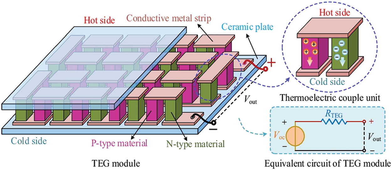
Figure 1: Schematic of TEG and equivalent circuit of TEG module. Reproduced with permission from reference [8]
When the temperature difference occurs between the two sides of thermocouple, the thermoelectric materials experience a diffusion of charge carriers (holes or electrons), resulting in the generation of an electric voltage. The efficiency
where Th is the temperature of the hot end, Tc is the temperature of cold end for the thermoelectric module (TEM) (K), and
where
With the development of material technology, thermoelectric generators receive various applications across different industries and sectors, such as waste heat recovery [14], automotive [15], medical device [16], wearable technology [17–19], asphalt pavements [20] and energy harvesting from renewable sources [9]. Nevertheless, the broad deployment of TEGs faces a challenge due to their limited efficiency in converting low-grade energy into high-grade energy, as well as the inherent characteristics of thermoelectric materials. Additionally, the limited temperature range and high heat dissipation further restrict their large-scale implementation. Many studies have been devoted to overcoming these limitations by advanced cooling techniques and heat transfer materials, system integration techniques and materials techniques. Various methods have been proposed to enhance the operating efficiency of TEGs. These methods include optical and thermal management techniques, multistage TEG configurations, innovative TEM designs, and the integration of hybrid TEG systems. Some comprehensive reviews have been conducted to evaluate the thermoelectric systems, mainly including the characteristics and applications [21], and recent progress [22] of TEGs, thermoelectric heating, cooling, and electricity generators in field of solar energy [23,24], harvesting energy from environmental energy [9] and from asphalt pavement [25], the different classifications of heat sinks for TEGs [26], the configurations of hybrid systems combining concentrator photovoltaic (PV) and TEG technologies [27–30] (under space conditions [31]) and TEG-PCM (phase change material) systems [32], etc. These studies provide a comprehensive review of the characteristics, applications, progress, configurations and some hybrid systems.
However, there is a dearth of comprehensive reviews that thoroughly analyze the system configuration, performance, and applications of thermoelectric generators driven by the sun and/or deep space. The progress in energy storage management, optical management, solar absorber materials, radiative cooler materials, and the combination mechanisms and optimization strategies for solar- and/or radiative cooling-driven thermoelectric generators are not yet well understood. Reasonable and effective optimization strategies to address the challenges and problems in the process of thermoelectric generators driven by solar and/or radiative cooling are not clear. Therefore, this work aims to systematically review the system configurations, performance, and applications of thermoelectric generators driven by solar energy and/or radiative cooling. Fig. 2 illustrates the schematic diagram of thermoelectric generators driven by solar energy and/or radiative sky cooling. This review comprehensively covers non-concentrating, optical-concentrating, and thermal-concentrating strategies for solar-driven thermoelectric generators (STEGs), non-concentrating radiative cooling-driven thermoelectric generators (RCTEGs), one-coating and dual-coating approaches for simultaneously driven by solar energy and radiative sky cooling (i.e., dual-mode thermoelectric generators (DM-TEGs)), and materials for solar absorbers and radiative coolers. The review also analyzes thermoelectric generators driven by solar and/or radiative cooling from the perspectives of system configuration, new materials for solar absorbers and radiative coolers, simulation and computation techniques, advanced thermal management, and applications. Finally, the future research directions and prospects of thermoelectric generators driven by solar and/or radiative cooling are discussed. This comprehensive review provides a comprehensive analysis of a novel mode of solar energy and deep space cooling energy collection. The multi-faceted analysis can serve as a reference to improve the efficiency of environmental energy collection, reduce costs, and expand the range of applications.
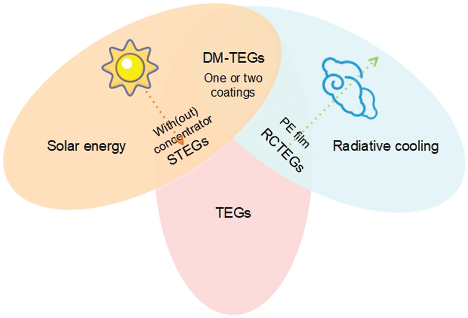
Figure 2: Schematic diagram of TEGs driven by solar energy and/or radiative sky cooling
2 Solar-Driven Thermoelectric Generators: System Configurations, Performance and Applications
Solar-driven thermoelectric generators operate on the principle of the Seebeck effect. When TEGs are exposed to sunlight, they absorb solar radiation, which leads to the conversion of solar energy into heat. Consequently, a temperature gradient is generated between the two ends. This temperature gradient is then utilized to drive the thermoelectric process, providing a direct and sustainable means of converting solar energy into electricity. This section presents an overview of solar-driven thermoelectric generator (STEG) technology, system configuration without concentrators and various solar concentration techniques, such as optical concentrations and thermal storage based on phase change materials (PCMs), are categorized and discussed, underscoring their potential to enhance the efficiency of STEGs.
2.1 Solar-Driven Thermoelectric Generators without Concentrators
STEGs have the ability to directly convert solar energy into electrical power, with the key component being the selective solar absorber (SSA), which efficiently absorbs sunlight and converts it into heat. Subsequently, thermoelectric materials are utilized to convert the temperature gradient generated by the absorbed solar energy into electrical energy. However, it is important to note that the efficiency of can be limited, particularly under non-concentrated sunlight conditions. To overcome this limitation and enhance overall performance, STEGs are often integrated with other systems to form combined heat and power (CHP) systems. These systems leverage the capabilities of TEGs alongside other energy conversion technologies to maximize overall efficiency and energy utilization. In addition, the integration of STEGs with other systems in CHP configurations opens up possibilities for various applications. The combined heat and power systems can provide a sustainable and reliable energy solution for both residential and commercial settings.
Lv et al. [33] have introduced a CHP system that integrates selective absorbing coating (SAC), micro-channel heat pipes (MCHPs), TEGs, and double-skin glass evacuated-tube technology. The schematic diagram of this system is depicted in Fig. 3. The system performance was examined by thermal resistance network (TRN), which is a mathematical model to analyse the performance of thermal systems by dividing the systems into discrete thermal resistances and nodes, interconnected by thermal conductance. The findings suggest that once the solar irradiation surpasses 700 W/m2 and the water temperature reaches 13°C, the system attains a peak power output of 659 mW at a load resistance of 4.2 Ω. Additionally, the system efficiency is recorded at 1.956%. Following that, Lv et al. [34] conducted an investigation into the cooling capabilities of the cold end of TEGs using three different heat exchange technologies: finned heat sink, heat exchanger, and heat pipe method. The results indicated that the utilization of the heat pipe showcased the highest output performance and net efficiency. Additionally, a parameter analysis was conducted by Li et al. [35] for the STEG-MCHP (micro-channel heat pipe) system, considering factors such as wind speed, ambient temperature, and the area of the selective absorbing coating. The findings from this analysis indicate that integrated system configuration leads to higher output power compared to series-connected TEGs under identical operating conditions. In addition to experimental investigations, Lv et al. [36] presented a novel numerical model, as illustrated in Fig. 4, which takes into account heat losses within a TEG and optimizes heat management. The numerical and experimental findings highlight a remarkable enhancement in the thermoelectric conversion efficiency, leading to a maximum electrical efficiency of 5.2% and a maximum exergy efficiency of 7.17%. As depicted in Fig. 5, Zhang et al. [37] developed a numerical model for the CHP system to forecast the system performance. The results indicate that when the figure of merit ZTM reaches 0.59 and the solar radiation remains below 1000 W/m2, the system can yield an estimated electrical energy output of approximately 0.19 kW·h, while generating around 300 L of hot water at a temperature of 55°C within a single day.

Figure 3: The schematic diagram of a unit of the high-performance solar thermoelectric system for combined heat and power. Reproduced with permission from reference [33]
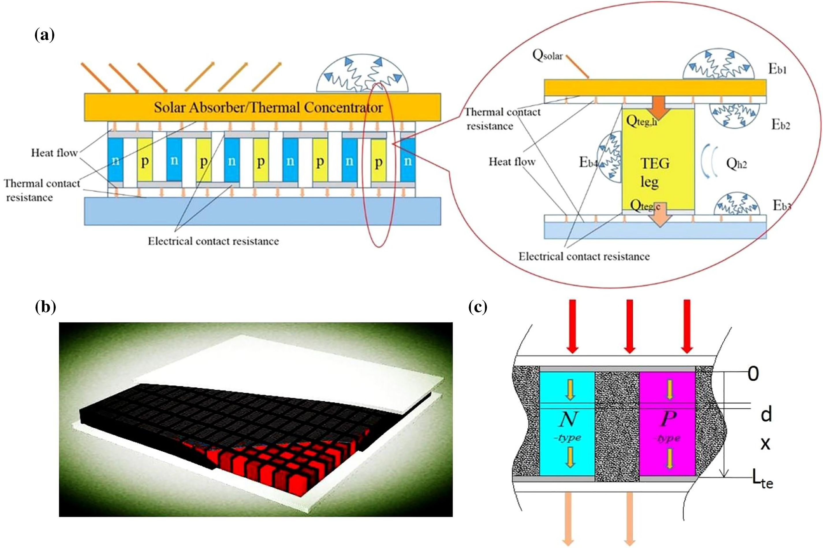
Figure 4: Schematic of a STEG and thermoelectric (TE) elements for numerical simulation of TE device. (a) Energy balance. (b) TE device with adiabatic fillers. (c) Discretization of thermoelectric (TE) elements for numerical simulation of STEG. Reproduced with permission from reference [36]
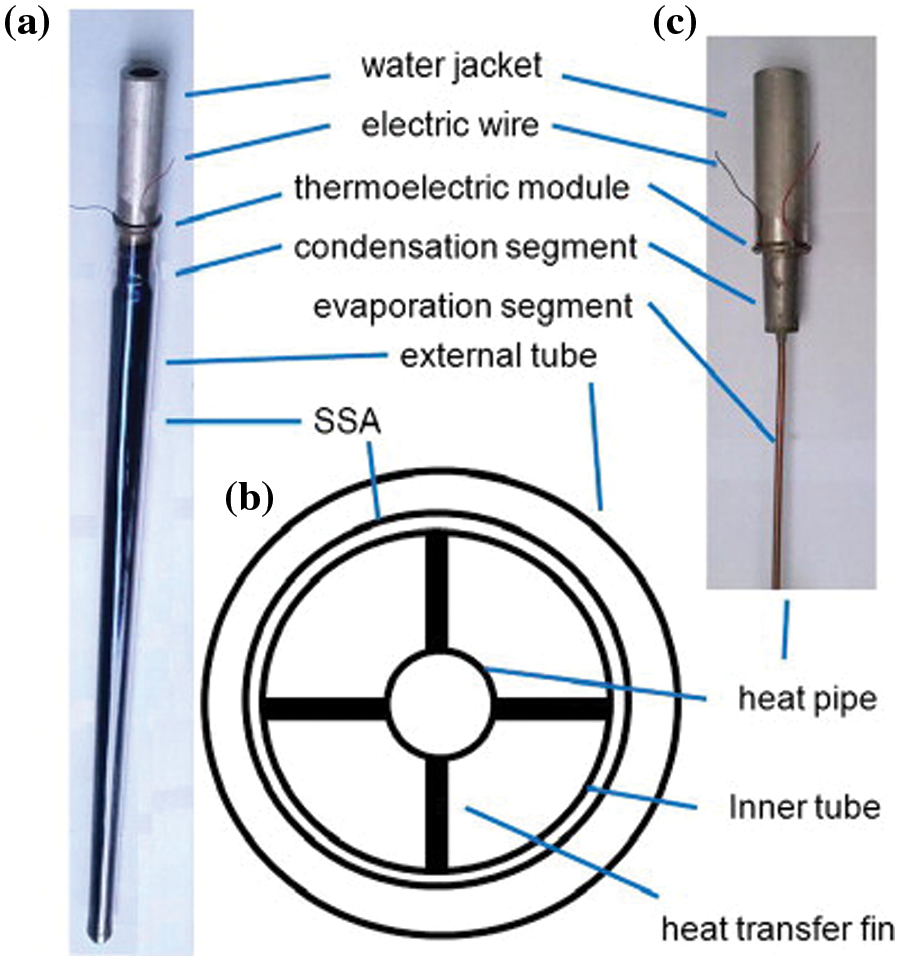
Figure 5: The structure of an evacuated glass tube with TEM. (a) A glass tube with TEM; (b) schematic cross-section of the evacuated tube; and (c) top section of the tube with external tube, inner tube and fins removed to reveal the heat pipe. Reproduced with permission from reference [37]
Another noteworthy development in non-concentrated solar-driven thermoelectric generator technology comes from the research conducted by Li et al. [38]. In their study, they explored innovative methods to enhance the solar absorption capabilities of a commercial TEG. By applying a mixture of nanoscale carbon black powders and polyvinylidene fluoride (PVDF) as the solar absorber and incorporating an insulating sponge to minimize heat loss, the system demonstrated a notable power generation of 3.3 mW under an irradiance of 1 kW/m2. Furthermore, when the systems were connected in series, they exhibited the capability to charge modern electronic devices at a rate of approximately 5% per hour.
The integration of advanced materials and innovative system configurations has led to enhanced efficiencies and increased power generation capabilities. These advancements bring us closer to a future where non-concentrated solar-driven TEGs can play a vital role in sustainable energy systems.
2.2 Solar-Driven Thermoelectric Generators with Concentrators
Recently, researchers have directed their efforts towards improving the performance of STEGs operating in concentration mode. Solar concentrators are optical devices used to enhance the collection and concentration of sunlight in solar energy systems. These devices utilize various optical principles to concentrate sunlight onto a smaller receiving area, thereby increasing the intensity of the captured sunlight. There are several types of concentrating optics, including flat plate concentrators [39] (Fresnel lens [40,41]), parabolic dish reflectors [12,42,43], and solar power towers [44].
In the context of research focused on a pair of n/p-type thermoelectric legs, attention has been directed towards investigating their performance. Kraemer et al. [45] developed a STEG cell, as shown in Fig. 6, which comprises a set of p- and n-type TE elements and a selective solar absorber surrounded by a glass enclosure to keep an evacuated environment. The STEG demonstrates a maximum efficiency of 4.6 under 1000 W/m2 with a concentrator ratio of 299. Subsequently, as shown in Fig. 7, Kraemer et al. [46] conducted a study on the performance of TEGs utilizing a pair of n/p-type segmented TE legs composed of doped bismuth telluride (Bi2Te3) and skutterudite materials, revealing a peak efficiency of 9.6% with a solar radiation intensity of 211 kW/m2. After accounting for optical losses, the system efficiency is found to reach 7.4%. Baranowski et al. [47] developed a comprehensive heat transfer model for STEGs, considering temperature-dependent properties of idealized materials. This model allows for the estimation of peak theoretical efficiencies achievable by STEGs and provides valuable design principles for such systems.
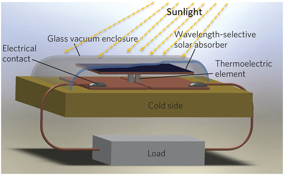
Figure 6: Structure of a STEG cell. Adapted from reference [45]
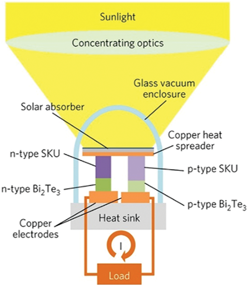
Figure 7: Concentrating STEG concept and proof-of-concept experiment. Adapted from reference [46]
Research focused on commercially available integrated TEGs utilizing multiple pairs of n/p-type thermoelectric legs has also been conducted. These studies aim to investigate the performance and optimize the design of such TEG systems in order to enhance their overall efficiency and practical applicability.
Novel materials and innovative designs have been instrumental in driving significant advancements in the field of thermoelectric energy conversion. Li et al. [41] focused on fabricating a solar absorber using carbon nanotubes (CNTs) and customizing a thermoelectric module with a liquid-cooled cold stage, as depicted in Fig. 8. The system achieved remarkable results, with a maximum efficiency of 4.3% operating at 78 suns, a peak power output of 11.2 W, and a highest output voltage of 11.6 V under a solar intensity of 106 kW/m2. Notably, a substantial temperature difference of 178°C was achieved. In a similar vein, Kim et al. [48] proposed a new system configuration incorporating a novel CuO nanoflake solar absorber, as illustrated in Fig. 9. To enhance the system performance, they integrated a highly transparent aerogel for improved optical and thermal management. The STEG equipped with an aerogel window demonstrated remarkable results, generating power that was 54% higher compared to the glass-covered STEG and 71% higher compared to the uncovered STEG. Candadai et al. [40] conducted a study specifically focusing on the performance of a series stacked combination of three Bi2Te3 TEGs, as shown in Fig. 10. The researchers aimed to investigate the potential benefits of this stacked configuration. Impressively, under matched load conditions, with a solar radiation of approximately 845 W/m2 and a concentration ratio of 62, the three stacked TEGs achieved a conversion efficiency of 1.2% at a hot end temperature of 280°C.
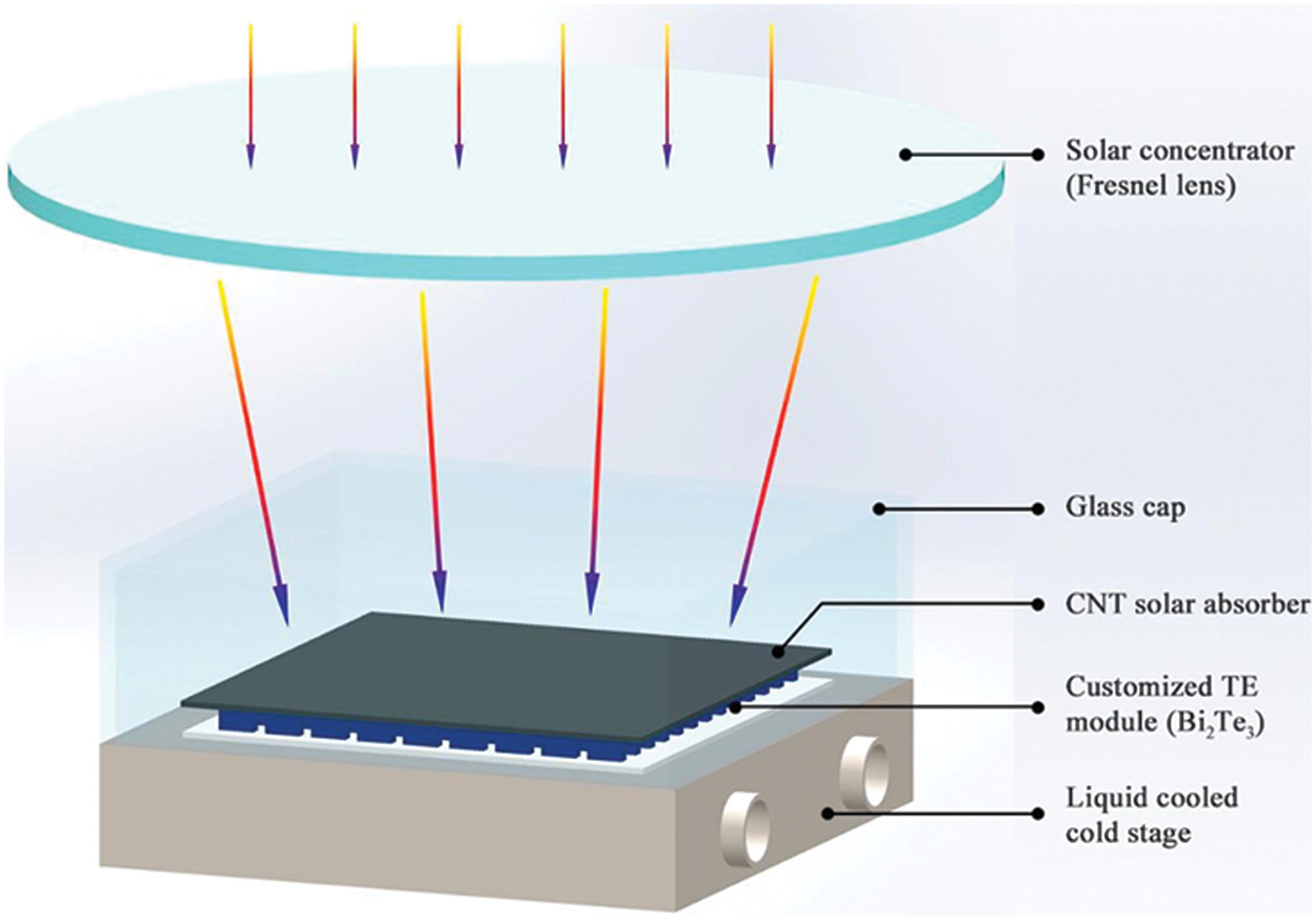
Figure 8: Schematic illustration of the STEG system based on nanostructured Bi2Te3 TE module. Reproduced with permission from reference [41]
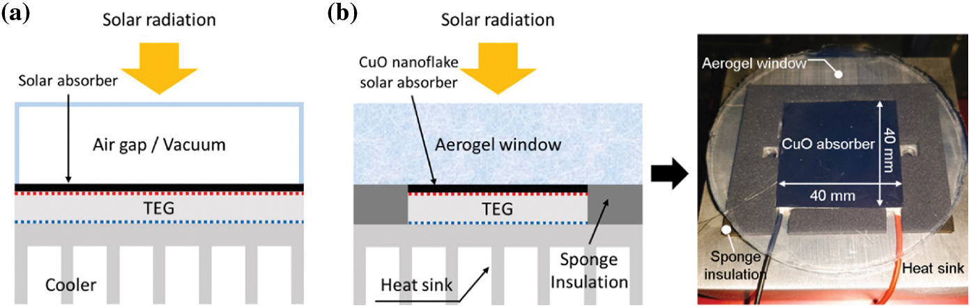
Figure 9: (a) Schematic illustration of a conventional STEG system with a transparent enclosure. (b) Schematic illustration and photograph of aerogel-covered STEG. Aerogel was replaced with soda-lime glass wafer or removed for performance comparison in the experimental section. Reproduced with permission from reference [48]
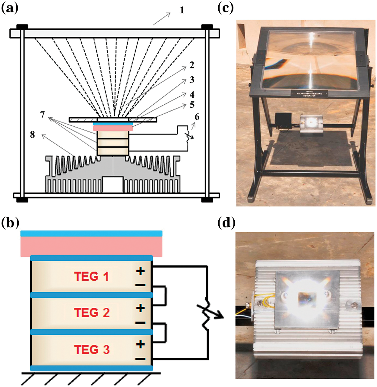
Figure 10: (a) Schematic of STEG experimental setup showing: (1) Fresnel lens (650 mm × 490 mm); (2) Solar concentration radiation; (3) Aluminum cover plate; (4) High temperature solar selective coating (35 mm × 35 mm); (5) Stainless steel substrate with IR reflector; (6) Variable resistor; (7) Thermoelectric modules; (8) Aluminum heat sink. (b) Thermally parallel stacked arrangement of commercial Bi2Te3 thermoelectric modules electrically connected in series. (c) Rooftop experimental setup of STEG with adjustable Fresnel lens frame to ensure that absorber receives direct normal irradiation of the sun. (d) Concentrated solar focal spot on the spectrally selective absorber surface at a concentration ratio of 65. Aluminum heat sink is visible below. Reproduced with permission from reference [40]
Due to limitations posed by experimental conditions, some studies have utilized heaters [49] (a mica heating plate [50] and a cartridge heater [43]) as substitutes for solar simulators to facilitate better control of parameters. This approach allows researchers to explore and analyse the performance of concentrated solar thermoelectric generators under controlled conditions. However, it is important to note that while heaters provide a convenient means of parameter control, they may not fully replicate the complex interactions and characteristics of actual solar radiation.
Experimental research on concentrated STEGs has provided valuable insights into their performance. However, conducting experiments on STEGs can be time-consuming and expensive. To complement the experimental findings and gain a deeper understanding of the underlying mechanisms, numerical simulation studies have been conducted. Sun et al. [51] built a 3D transient thermal-electric simulation model using commercial software COMSOL to analyse the dynamic response through the input solar radiation for the hot end of a TEG. In their model, the temperature of the cold end is consistently maintained at 300 K throughout the operation. The average daytime output power and conversion efficiency at 150 suns is 13.16 W and 6.15%, respectively. Kossyvakis et al. [52] utilized the finite element method in ANSYS to compare the performance of two commercial TEG modules under thermal and optical concentrations. Sun et al. [50] presented a real-time simulation using ANSYS for the STEG system. The findings indicate that the optimal electrical load varies dynamically in response to fluctuations in solar irradiation throughout the day. Consequently, achieving an impedance match between the TEG and the electrical load is crucial to maximize energy extraction from the STEG. Through optimization simulation results, it was determined that an electrical load of 5.8 Ω is required to attain both the maximum power generation of 6.588 kWh/day and the peak efficiency of 2.657%. As previously mentioned, the majority of studies examining the impact of solar radiation and wind speed on the STEG system focus on direct sunlight and wind passing parallel to the hot side surface. However, Nayak et al. [53] numerically conducted an investigation specifically exploring the influence of the angle of attack (AOA) and wind direction on the solar radiation for the STEG system, as illustrated in Fig. 11. The study reveals that the peak limiting input heat flux occurs at an angle of attack of 30 degrees. Furthermore, at a wind speed of 5 m/s, the heat flux reaches 24,000 W/m2 for this specific angle of attack. Moraes et al. [54] investigated the effect of air speed on a STEG apparatus, consisting of a solar evacuated tube and a CPU cooler as the hot and cold sources.
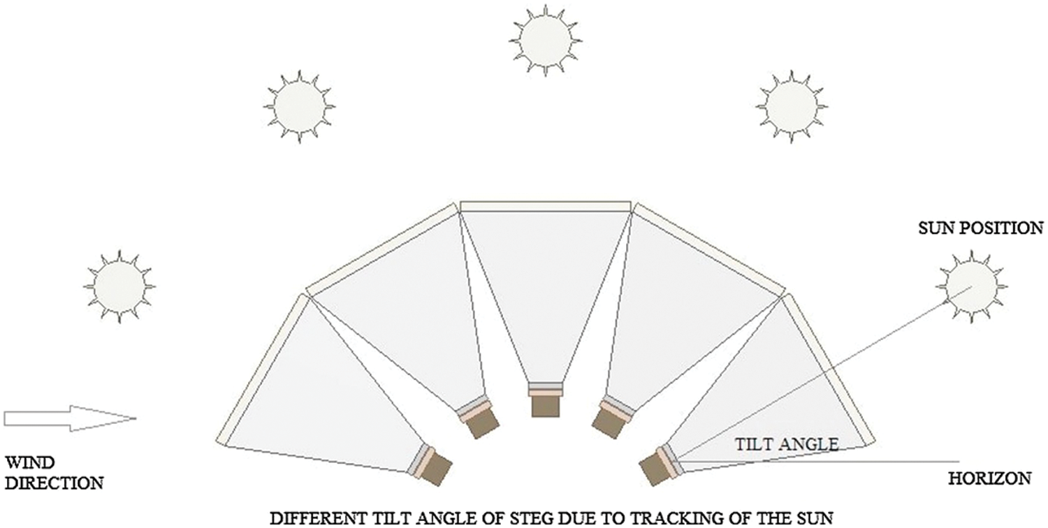
Figure 11: Schematic of the TEG test assembly tilt angle with the diurnal sun movement and angle made with the oncoming wind. Reproduced with permission from reference [53]
In addition to utilizing commercial software, researchers have also conducted self-programmed studies to simulate and analyse concentrated STEGs. A common approach in these studies involves employing thermal resistance networks (TRNs) [43,49,55]. Ji et al. [49] investigated the impact of various geometry parameters of the STEG system. These parameters include the leg height, ratio of the cross-section area of n-type legs over p-type legs, and the solar concentration ratio. To determine the optimal geometry parameter settings, the Taguchi method is employed. Escobar et al. [43] built upon the thermosyphon-based STEG model proposed by Miljkovic and Wang [56]. They designed an experimental setup, as illustrated in Fig. 12. In their study, the TEG was placed between the cartridge heater, which emulated the sun and the parabolic concentrator, and the condensate zone of the thermosyphon. The system achieved impressive results, with the TEG generating an electrical power output of 96 mW and a recovered heat output of 68.18 W, when a total power of 118 W was supplied through the heater. Ge et al. [57] developed a mathematical model for the STEG system incorporating spray cooling and conduct a comparative analysis with water cooling. Montero et al. [55] utilized PCMs for energy storage in a STEG system, as shown in Fig. 13. By integrating 6 kg of PCMs and a 2.5 kg copper heat sink, the cooling system maintained a cold end temperature of approximately 80°C for the TEG. This setup resulted in a peak temperature difference of 120°C between the two ends of the TEG, demonstrating the effectiveness of PCMs in energy storage and temperature management. Furthermore, the STEG achieved a notable electricity generation of approximately 0.6% during nighttime.
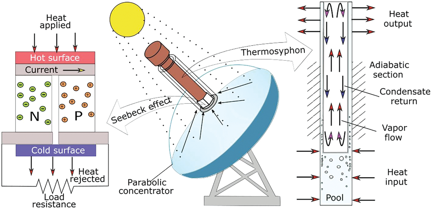
Figure 12: Schematic of the hybrid solar thermoelectric system. Reproduced with permission from reference [43]
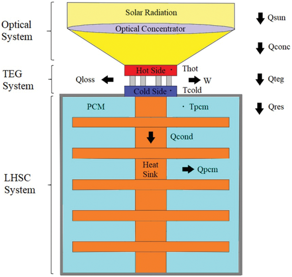
Figure 13: Schematic of STEG coupled LHSCS system. Reproduced with permission from reference [55]
After discussing the experimental and numerical research on concentrated solar thermoelectric generators, it is crucial to address the subsequent research and analysis exploring their potential applications. Bellos et al. [58] conducted a comprehensive analysis to evaluate the energy and financial advantages of employing a small module consisting of paired p- and n-type TE elements. Subsequently, they applied this system to a 100 m2 solar field located in Athens, Greece, and assessed its performance on an annual basis. The STEG system demonstrated an impressive electrical efficiency of 3.2%, while the collector achieved a notable thermal efficiency of approximately 79.2%. These results highlight the system’s effectiveness in efficiently converting solar energy into both electricity and thermal energy. In terms of financial viability, the analysis revealed promising findings. The estimated payback period for the system was calculated to be 4.55 years, indicating a relatively short time frame for recovering the initial investment. Moreover, the levelized cost of electricity, which considers the total lifetime costs of the system, was estimated to be around 0.0441 €/kWh. This suggests that the STEG system is cost-effective and competitive compared to conventional energy sources. Ohara et al. [59,60] developed an exergetic analysis model for a residential solar combined heat and power generation system using TEGs, as depicted in Fig. 14. Their study reveals the promising application potential of this system. The outcomes indicate that maximizing any of the three conditions—electricity generation, combined efficiency, or exergetic efficiency—leads to a significant decrease in the remaining two conditions. The researchers found that the STEG system exhibited peak performance when operating at a heat production temperature of 650 K. At this optimal point, the system achieved an impressive combined efficiency of 49% and an exergetic efficiency of 18%. Muthu et al. [12] conducted an analysis on the performance of a solar parabolic dish TEG that incorporates PCMs on the cold end. The experimental setup is illustrated in Fig. 15. Through their experimental investigations, the researchers observed that the TEG reached a remarkable maximum receiver plate temperature of 120°C when exposed to solar beam irradiation of 1.1 kW/m2. This research highlights the potential application of utilizing PCMs in solar parabolic dish TEG systems for enhanced performance.
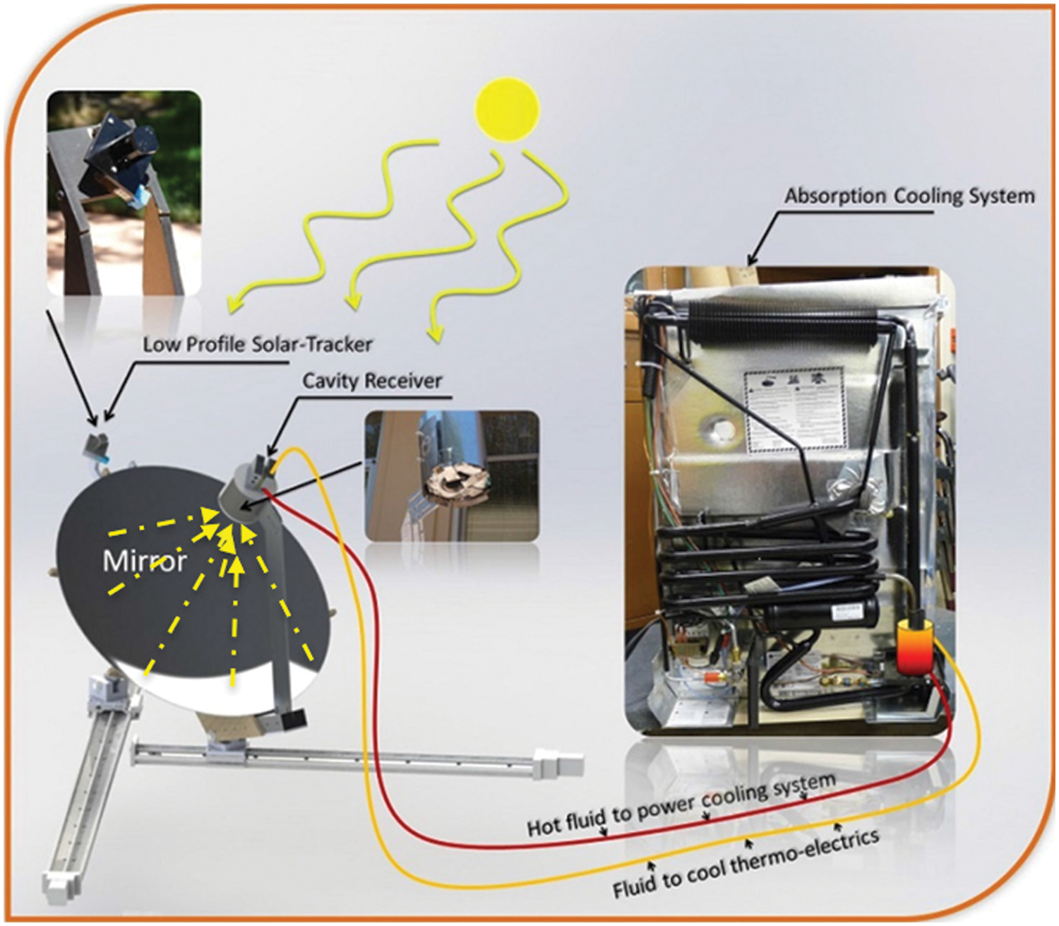
Figure 14: Solar thermoelectric system set-up. Adapted from reference [60]
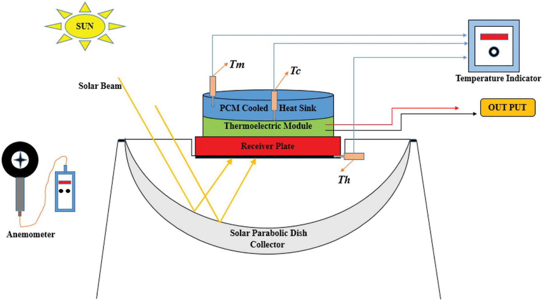
Figure 15: Line diagram of the experimental setup. Reproduced with permission from reference [12]
Solar thermoelectric generators are a specific application of concentrators that use thermoelectric elements and selective solar absorbers (SSAs) to convert concentrated sunlight into electricity. Research has focused on optimizing STEG performance, considering factors like concentrator ratio, cooling methods (spray cooling, water cooling), and geometry parameters. Studies have demonstrated peak efficiencies ranging from 4.6% to 9.6%, with improved efficiencies after accounting for optical losses. Mathematical models and simulations have been developed to analyse and forecast STEG performance. Hybrid systems, such as combinations with thermosyphons and CHP systems, have also been explored. Overall, research aims to enhance the efficiency and practicality of solar concentrators and STEGs for sustainable energy generation.
2.3 Comprehensive Discussions on Solar-Driven Thermoelectric Generators
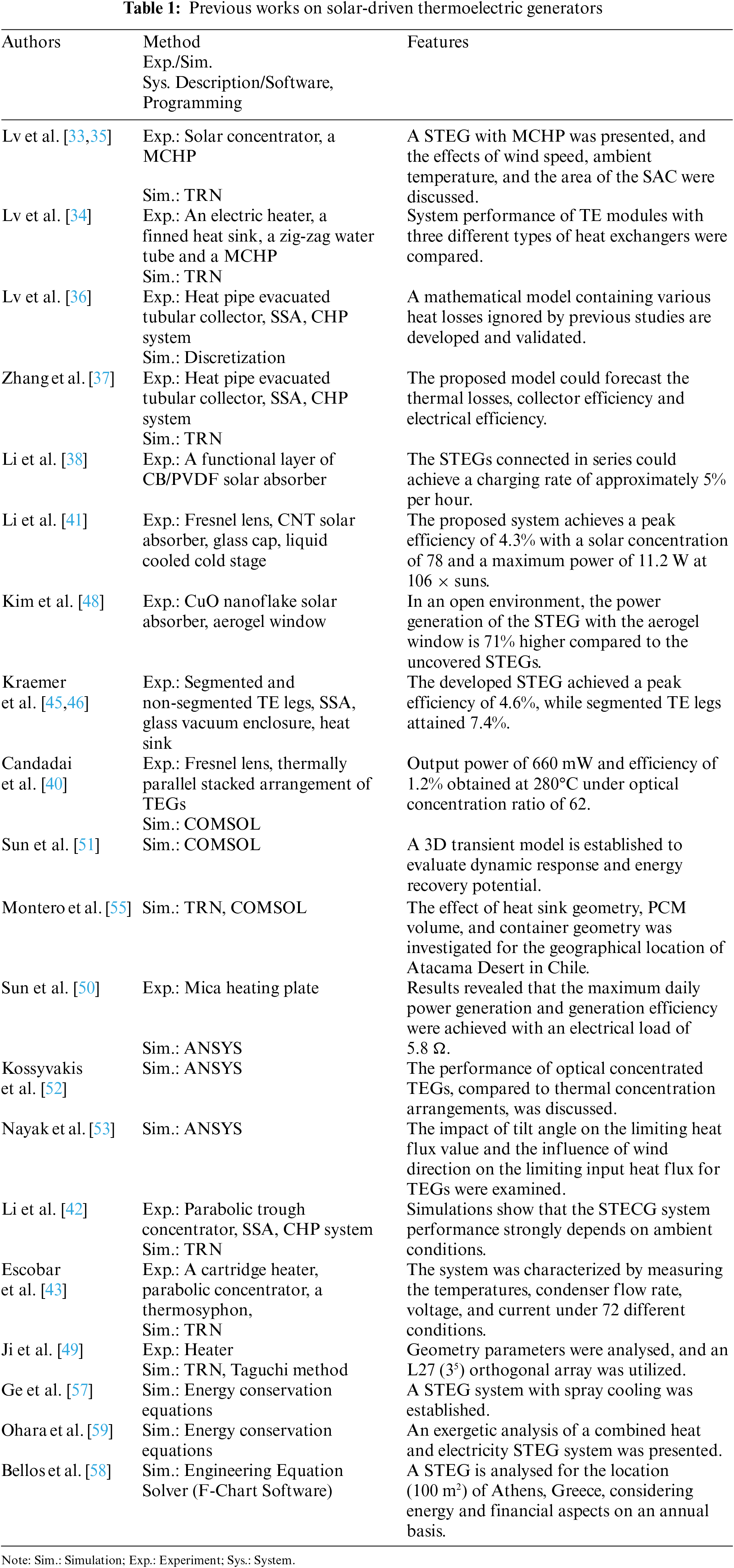
Solar-driven thermoelectric generators have attracted significant research attention due to their potential as a sustainable and efficient energy conversion technology. In this section, we will delve into comprehensive discussions on various aspects related to STEGs, including system configuration, new materials, numerical models and limitations of thermal resistance networks, advanced thermal management, and applications with a focus on combined heat and power systems based on TEGs under concentrated solar energy. Table 1 provides an overview of some previous works in STEGs, highlighting the different methods, features, and experimental or simulation approaches.
The configuration of a STEG refers to the arrangement and integration of different components to maximize energy conversion efficiency. Researchers have explored various system configurations, including the use of solar concentrators, MCHP systems, and specific heat exchangers.
Solar concentrators play a crucial role in STEGs as they concentrate sunlight onto the thermoelectric elements, increasing the temperature gradient and improving overall efficiency. Different concentrator designs, such as parabolic troughs and Fresnel lenses, have been investigated to optimize the concentration ratio and minimize optical losses. CHP systems have been integrated into STEGs to enhance overall system performance. These systems allow for simultaneous electricity generation and utilization of waste heat, maximizing the utilization of available energy. Additionally, the design and selection of heat exchangers have been studied to improve heat transfer efficiency. Various types of heat exchangers, including finned heat sinks, zig-zag water tubes, and heat pipe evacuated tubular collectors, have been evaluated to enhance thermal management and increase the temperature difference across the thermoelectric modules.
The choice of materials used in solar-driven thermoelectric generators is crucial for achieving efficient energy conversion. Researchers have been actively exploring new materials, particularly for solar absorbers, with the aim of enhancing the overall performance of STEGs. Here, we discuss three prominent examples of new materials used as solar absorbers as shown below:
A functional layer of CB/PVDF solar absorber has been investigated as a promising material for efficient solar absorption in STEGs. This composite layer consists of carbon black (CB) nanoparticles embedded in a polyvinylidene fluoride matrix. The CB nanoparticles facilitate the absorption of solar radiation across a wide range of wavelengths, while PVDF provides mechanical stability and electrical insulation. This combination enhances the absorption efficiency of the solar radiation, contributing to improved overall performance of the STEG. Carbon nanotubes have also attracted significant attention as solar absorber materials in STEGs. CNTs possess unique optical properties, such as a high absorption coefficient and broad spectral absorption range. These properties make CNTs excellent candidates for efficient solar radiation absorption. By incorporating CNTs into the solar absorber layer, STEGs can effectively capture a larger portion of the incident solar energy, leading to enhanced energy conversion efficiency. Furthermore, CuO nanoflake-based solar absorbers have been explored for their potential in STEGs. CuO nanoflakes offer a high absorption coefficient and excellent thermal stability, making them suitable for efficient solar energy absorption. The unique nanoscale morphology of CuO nanoflakes provides a large surface area, allowing for more effective absorption of solar radiation. This enables STEGs to harness a greater amount of solar energy and enhance the overall performance of the system.
It is worth noting that these new materials for solar absorbers represent only a few examples of the ongoing research in the field. Researchers continue to explore and develop novel materials with improved properties, such as higher solar absorption efficiency, enhanced thermal stability, and compatibility with other components of the STEG system. The development of new materials for solar absorbers holds great potential for advancing the efficiency and applicability of STEGs in harnessing solar energy for sustainable power generation.
2.3.3 Limitations of Thermal Resistance Networks
Numerical modelling plays a crucial role in understanding and optimizing the performance of STEGs. As shown in Table 1, one commonly used modelling approach is the TRN method. Thermal resistance networks simplify the complex heat transfer processes within a STEG by dividing the system into thermal resistances and capacitances, enabling efficient simulations and analysis. However, it is important to note that TRNs have certain limitations. They assume uniform temperature distributions and neglect localized effects, which may be significant in practical STEG configurations. TRNs also do not consider material anisotropy and the full complexity of heat transfer mechanisms, limiting their accuracy in capturing the intricacies of heat transfer within the system.
2.3.4 Advanced Thermal Management
When STEGs operate under concentrated sunlight conditions, effective thermal management becomes crucial to prevent overheating and ensure long-term stability. Advanced thermal management techniques, such as microchannel cooling, heat pipes, and phase change materials, have been explored to efficiently dissipate excess heat and maintain optimal operating temperatures.
Microchannel cooling utilizes microscale channels to enhance convective heat transfer, enabling efficient cooling of thermoelectric modules. Heat pipes, on the other hand, utilize phase change heat transfer to rapidly transport and dissipate heat, ensuring effective thermal management. PCMs offer the advantage of high latent heat storage capacity. They absorb excess heat during peak solar radiation and release it during low radiation periods, providing passive thermal management and improving system performance.
2.3.5 Applications: Concentrated Solar Energy-Based CHP Systems
One significant application of STEGs is in the field of combined heat and power systems under concentrated solar energy. By utilizing solar concentrators, STEGs can generate both electricity and heat simultaneously, making them suitable for decentralized power generation and thermal energy utilization. CHP systems based on TEGs under concentrated solar energy find applications in residential and commercial settings, providing electricity for lighting, appliances, and other electrical loads while utilizing waste heat for space heating, water heating, or other thermal applications. These systems offer the advantages of improved energy efficiency, reduced reliance on conventional energy sources, and lower carbon emissions.
In conclusion, comprehensive discussions on solar-driven thermoelectric generators encompass system configuration, new materials, limitations of TRNs, advanced thermal management techniques, and applications such as combined heat and power systems. These discussions provide insights into the various aspects of STEGs, highlighting the ongoing research efforts and potential advancements in this promising field.
3 Radiative Cooling-Driven Thermoelectric Generators: System Configurations, Performance and Applications
Radiative cooling primarily operates within the infrared wavelength range. Specifically, it takes advantage of the atmospheric transparency to wavelengths between 8 and 13 μm, known as the atmospheric window. This range allows the emitted thermal radiation from objects to effectively escape into deep space, resulting in cooling effects. By utilizing materials and coatings with high emissivity within this specific wavelength range, radiative cooling systems can optimize their performance and achieve efficient heat dissipation.
3.1 Radiative Cooling-Driven Thermoelectric Generators
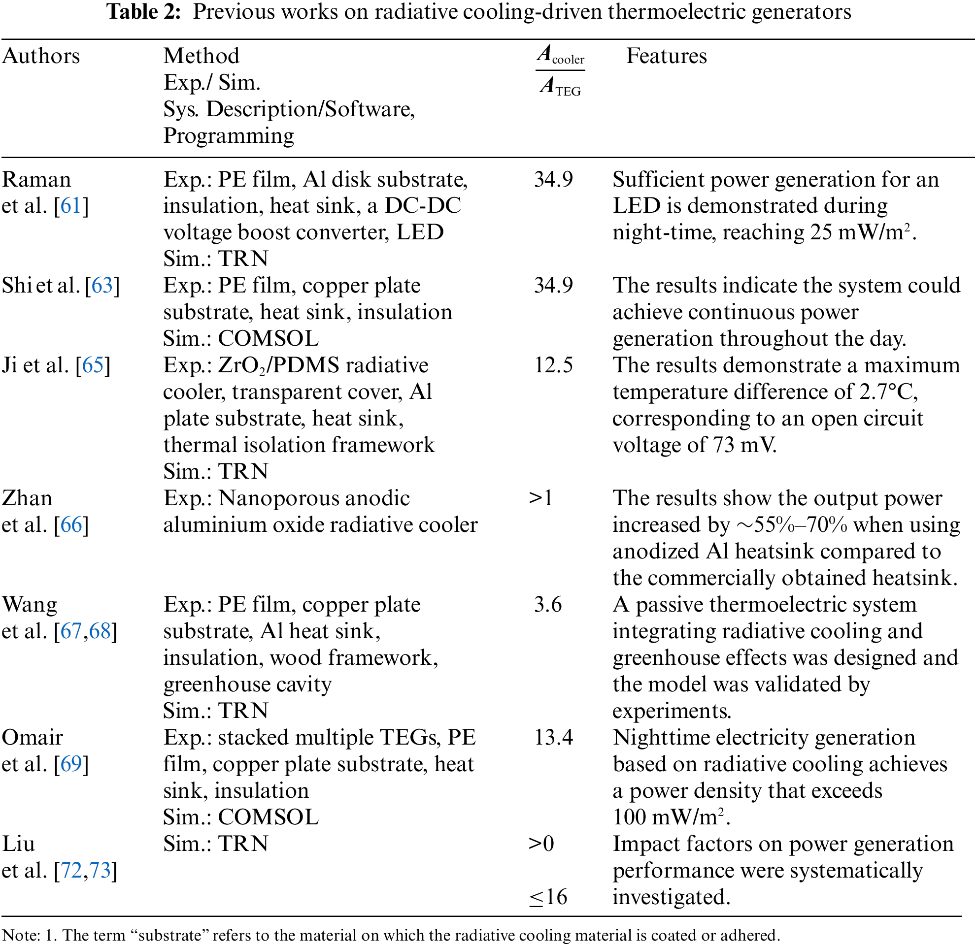
Radiative cooling-driven thermoelectric generator (RCTEG) systems typically comprise several key components, including a polyethylene (PE) film, radiative cooling paint, a copper or aluminium plate substrate, a TEG, a heat sink, and thermal insulation. Fig. 16 illustrates the schematic of RCTEG system and its key components, which is designed by Raman et al. [61], and the system can generate electricity to drive an LED at night. As shown in Fig. 16, the hot end of the TEG is heated by the surrounding environment and in contact with an Al block, beneath which there are aluminium fins used to enhance heating, rather than heat dissipation. While the cold end of the TEG, which is attached to an aluminium disk substrate coated with a commercially available black paint serving as the radiative cooler, is enveloped with a wind cover—a PE film—to minimize heat loss. The experimental results demonstrate that the open-circuit voltage of the system is around 80 mV, which is relatively low and insufficient to power an LED light. Therefore, the addition of a DC-DC voltage boost converter is required, as depicted in Fig. 16. It is worth noting that the boost converter mentioned is also passive, meaning that it does not require any input other than the input from the thermoelectric generator. The experiment data demonstrates that the system generates electricity with an output of 25 mW/m2. Additionally, under favourable conditions such as warm ambient temperature and a low dew point, the system has the potential for electricity generation of 0.5 mW/m2. The system configuration proposed by Zhang et al. [62] is similar to that of Raman et al. [61], with the only difference being the replacement of the thermoelectric generator with thermally regenerative electrochemical cycles. Additionally, they achieved a vacuum seal on the radiative cooler chamber encapsulated with a PE film. In comparison to the system configuration proposed by Raman et al. [61], Shi et al. [63] replaced the material of the substrate and used copper instead of aluminium.
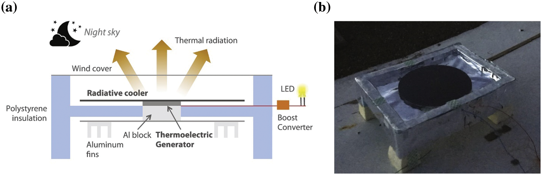
Figure 16: Device Operation Schematic and Picture. (a) Schematic of the low-cost night-time thermoelectric generator device and its key components. (b) Photo of the device in rooftop testing. Reproduced with permission from reference [61]
The system configuration pioneered by Raman et al. [61] is considered the most comprehensive and comprehensive for RCTEGs. Subsequent studies by other researchers are supplementary work that does not bring significant innovations to the system configuration. However, these studies have made new discoveries in terms of novel materials and structures. For instance, Zhang et al. [64] introduced a radiative cooling coating composed of a zirconia (ZrO2) embedded polydimethylsiloxane (PDMS) hybrid ZrO2/PDMS coating. Ji et al. [65] referenced their preparation method and conducted experimental and numerical investigations on the performance of RCTEG system. Furthermore, Zhan et al. [66] made significant progress by utilizing nanoporous anodic aluminium oxide (AAO) grown on aluminium surfaces to fabricate a radiative cooler. Moreover, they proposed a novel cooler structure, using the entire heat sink as the cooler, as shown in Fig. 17. Another innovative structure was firstly proposed by Wang et al. [67,68], as depicted in Fig. 18. This design combines the principles of radiative cooling and greenhouse effects. The greenhouse effect assists in trapping and retaining heat, thereby creating a warmer environment at the hot end of the TEG. A stacked configuration [69], similar to that employed in STEGs [40], as depicted in Fig. 19, has also been explored in research on RCTEGs.
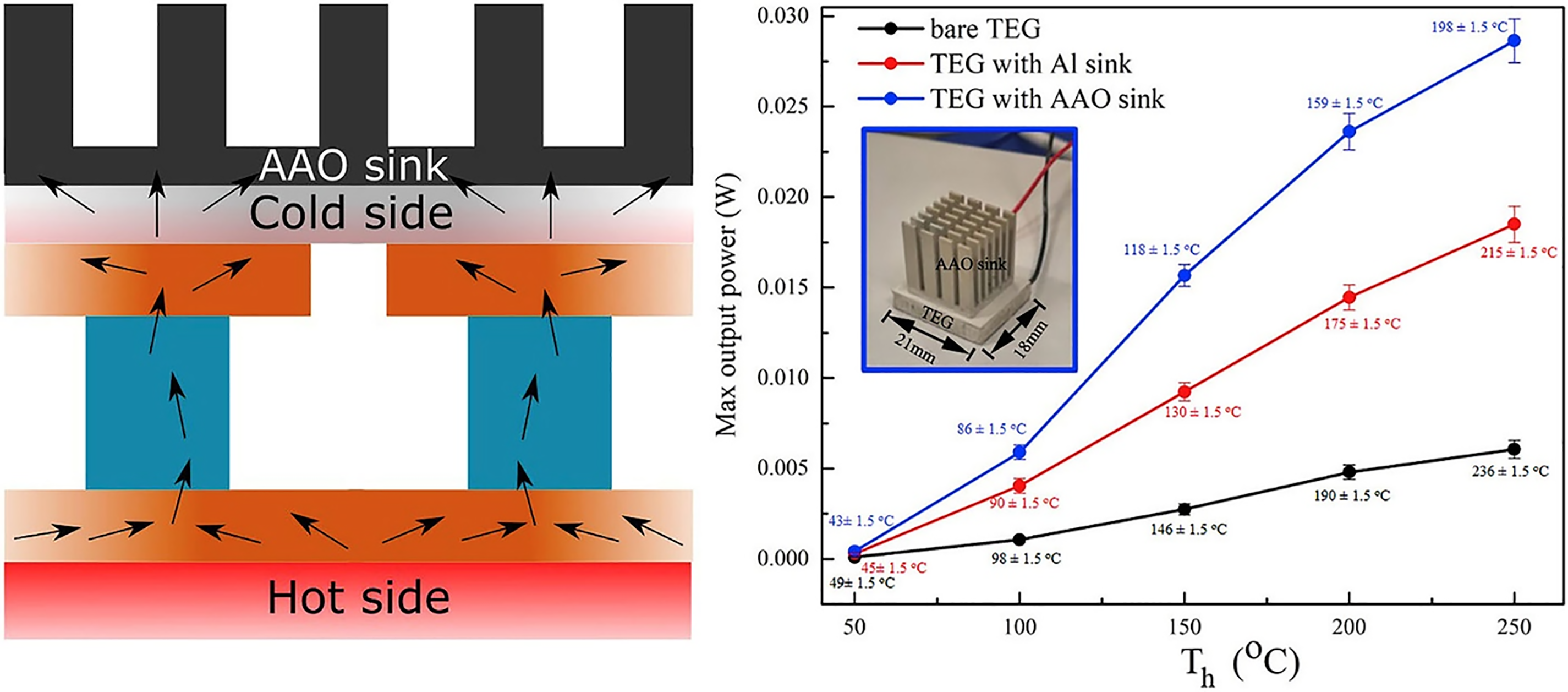
Figure 17: Radiative cooling of TEG with anodic aluminium oxide heat sink. Reproduced with permission from reference [66]
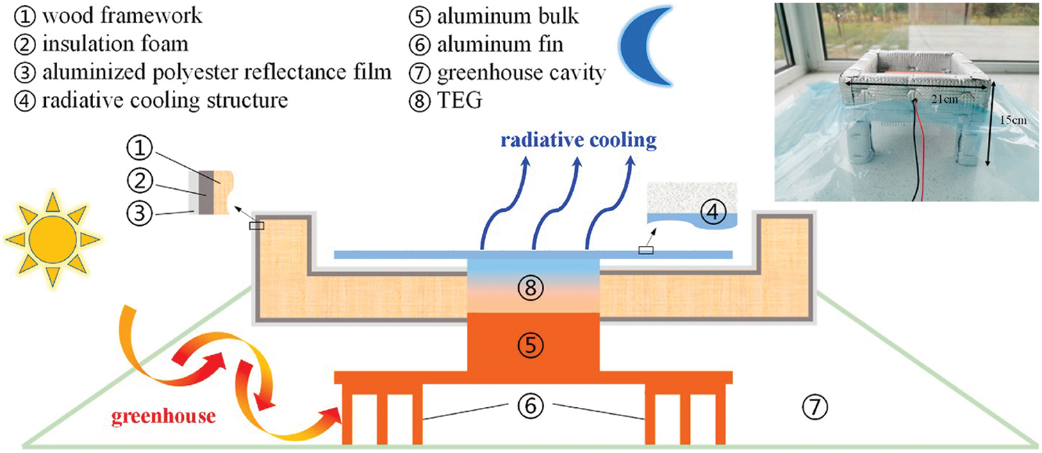
Figure 18: Sketch and experiment setup of the TEG system integrating radiative cooling and greenhouse effects. Reproduced with permission from reference [67]
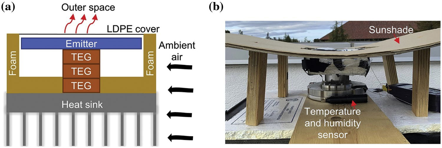
Figure 19: Experimental setup. Reproduced with permission from reference [69]
The summary of RCTEG systems, as presented in Table 2, includes an additional column specifically dedicated to “the area ratio between the cooler and commercial integrated TEGs (or P/N elements [70]),” which distinguishes it from Table 1. This is because the radiative cooling power emitted is approximately 100–150 W/m2, which varies based on the surface temperature of radiative cooler [71]. However, this power constitutes only a small fraction of the solar absorption (with solar intensity around 1000 W/m2) during the day. Therefore, a larger cooler area is needed to offset solar absorption during the day, while at night, it can provide greater cooling capacity. This is also the reason why, as indicated in Table 2, the area ratio between the cooler and TEGs is consistently greater than 1 in all the mentioned and forthcoming experimental studies on RCTEGs.
There have been relatively few simulation studies on RCTEG systems. Liu et al. [72] developed a numerical model focused on investigating the power generation capabilities of RCTEG systems. The model based on thermal resistance networks primarily consisted of a radiative cooler, a TEG, and a heater. In a subsequent study [73], the authors introduced specific modifications to the RCTEG system. These modifications involved replacing the heater with a heat sink and substituting the wind cover with a polyethylene aerogel (PEA), as illustrated in Fig. 20. In terms of power generation, the improved system demonstrated a notable enhancement of 24% in inland areas and an even more remarkable improvement of 71% in coastal regions compared to the system with the wind cover.
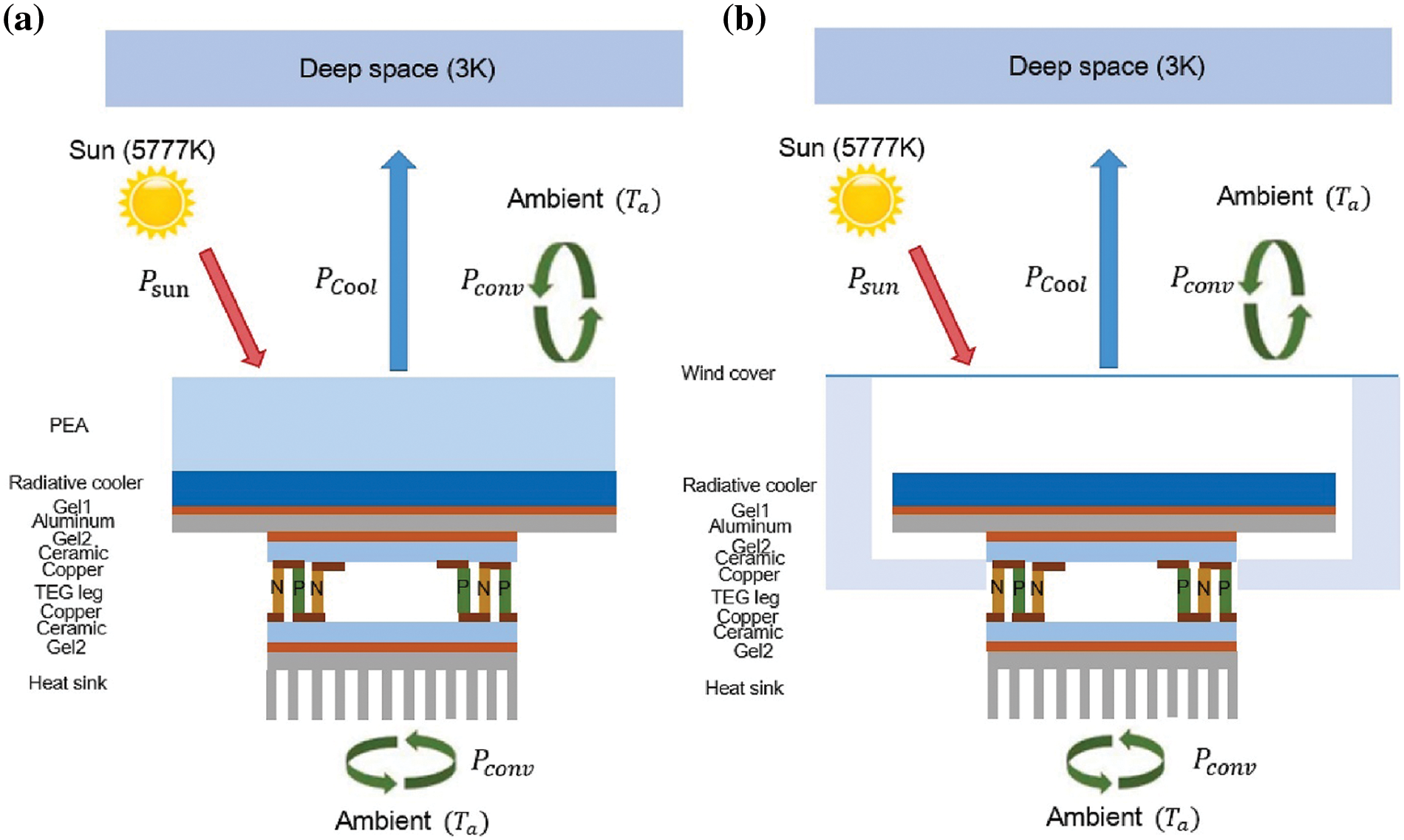
Figure 20: RC-TEG modules and energy conservation process. (a) Schematic of the proposed RC-TEG module with PEA. (b) Schematic of the existing RC-TEG module with PE wind cover. Reproduced with permission from reference [73]
For RCTEGs, there should also be research on concentrated mode, similar to STEGs. However, the author did not come across such studies at the time of writing. Nonetheless, there are studies on concentrated radiative cooling, as depicted in Fig. 21 [74]. It is anticipated that in the near future, research on RCTEGs with amplification techniques [75,76] will emerge.
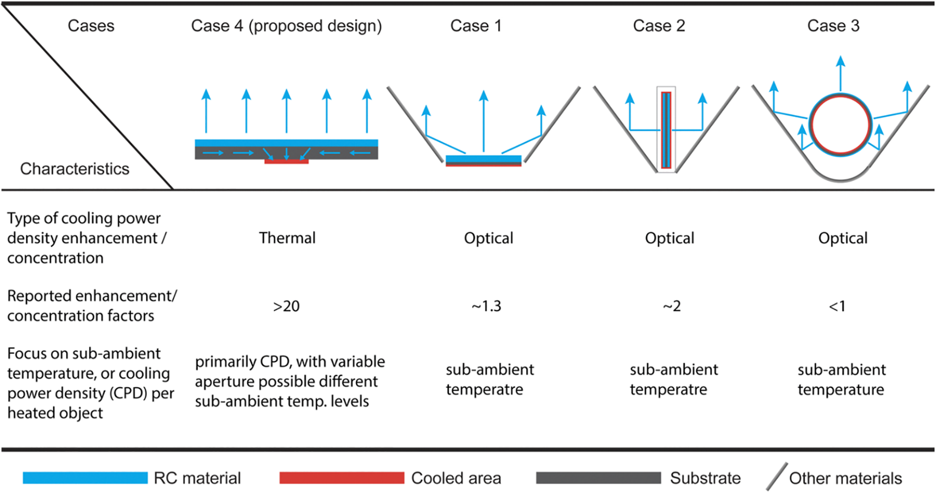
Figure 21: The introduction of current radiative sky cooling power density amplification approaches (Cases 4 [74], Case 1–3 [75–77]). Adapted from reference [74]
3.2 Comprehensive Discussions on Radiative Cooling-Driven Thermoelectric Generators
In this section, we provide a comprehensive discussion on radiative cooling-driven thermoelectric generators from various aspects, including system configuration, new materials and structures, numerical studies, and the future combination of TEGs with concentrated radiative cooling. Additionally, we explore apotential applications such as generating light from darkness for nighttime illumination and passive LED lighting.
The system configuration of RCTEGs has achieved a relatively mature stage, making it challenging to achieve significant breakthroughs beyond existing configurations proposed by Raman et al. [61]. The current configurations have been extensively studied, and further improvements may require innovative approaches. Exploring new materials and structures is a promising avenue for advancing RCTEGs. These studies have introduced novel materials, such as the hybrid ZrO2/PDMS coating and nanoporous AAO, and innovative structures, including the greenhouse effect design and stacked configuration. By leveraging these materials and structures, researchers aim to optimize the performance and efficiency of RCTEGs for various applications. Continued exploration and development in these areas hold great potential for advancing radiative cooling-driven thermoelectric generator technology.
Numerical studies on RCTEGs have been relatively limited, with a predominant focus on thermal resistance networks. However, there is a need for the development of new and advanced models to gain deeper insights into the complex heat transfer and electrical generation processes within RCTEG systems. The future combination of TEGs with concentrated radiative cooling presents a novel and intriguing avenue for enhancing their performance. However, this area is still in its early stages, and significant developments are needed.
Radiative cooling-driven TEGs offer potential applications beyond traditional power generation. One such application is generating light from darkness, which involves utilizing the temperature difference between the two ends of a TEG to power low-energy devices, such as passive LED lighting. This application contributes to sustainable and energy-efficient lighting solutions, particularly in off-grid or remote areas.
In summary, comprehensive discussions on radiative cooling-driven thermoelectric generators encompass various aspects. Continued research efforts in these areas will contribute to the advancement and practical implementation of RCTEG systems.
4 Thermoelectric Generators Simultaneously Driven by Solar Energy and Radiative Cooling: System Configurations, Performance and Applications
In recent years, the concept of thermoelectric generators simultaneously driven by solar energy and radiative cooling, which are dual-mode thermoelectric generators, has gained significant attention. This innovative approach combines the utilization of solar radiation for power generation during the day with radiative cooling for enhanced energy conversion during the night. In this chapter, we delve into the system configurations, performance characteristics, and applications of such DM-TEGs. Through a comprehensive analysis of the latest research and advancements, this chapter sheds light on the promising prospects and challenges associated with thermoelectric generators simultaneously driven by solar energy and radiative cooling.
4.1 One-Coating Approaches for Dual-Mode Thermoelectric Generators
In this section, we explore the utilization of one-coating approaches as an innovative method to achieve dual-mode operation in thermoelectric generators driven by solar energy and radiative cooling. These one-coating approaches involve the application of a single specific coating on the thermoelectric materials to optimize solar energy absorption and radiative cooling efficiency. We delve into the system configurations, performance characteristics, and potential applications of these one-coating techniques.
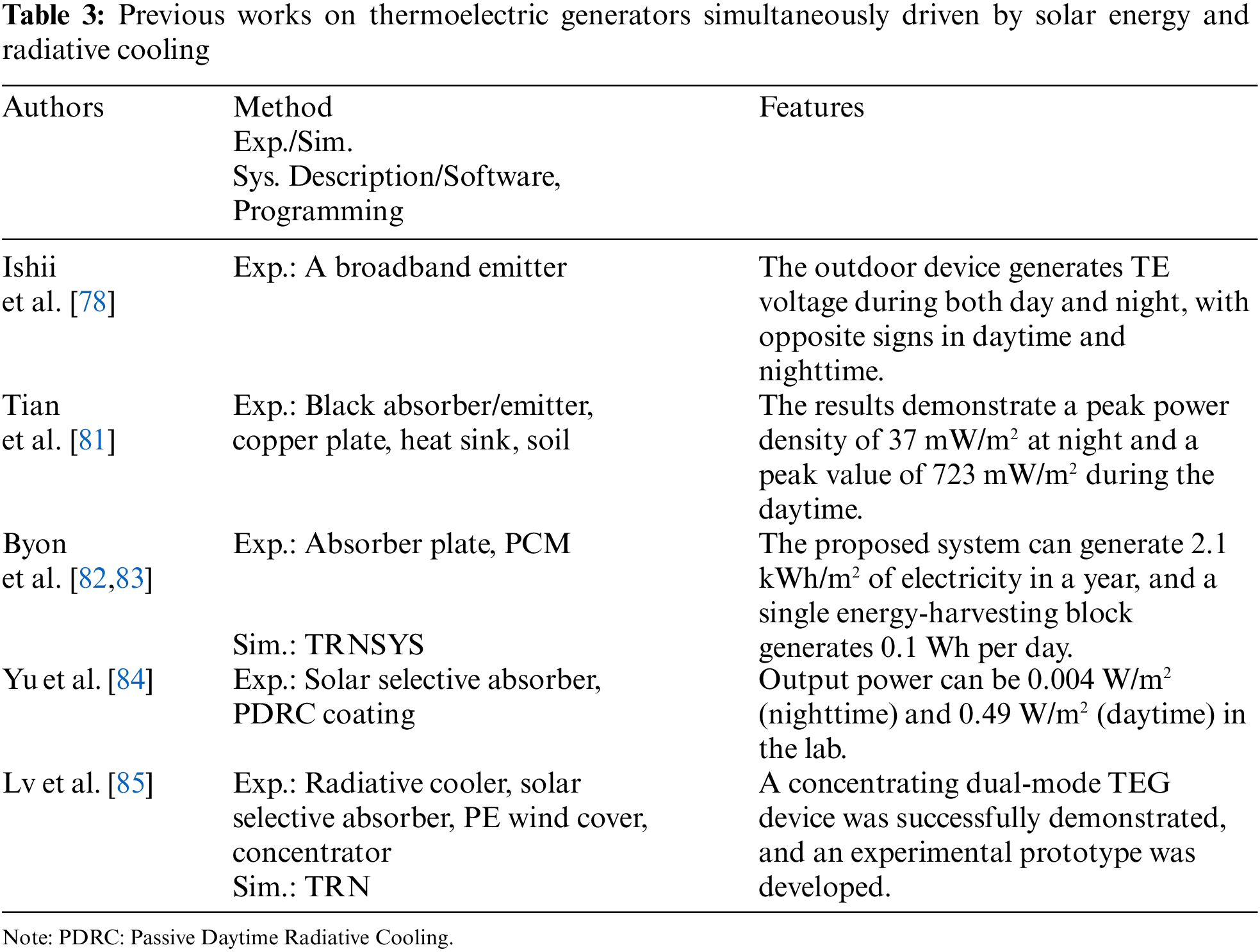
One approach for dual-mode thermoelectric generators is to utilize a broadband emissive coating that exhibits high absorptivity within the solar band and high emissivity within the atmospheric window. This approach allows TEGs to efficiently absorb solar radiation while effectively emitting thermal energy to the deep space through radiative sky cooling. This innovative approach allows for the generation of electricity not only during the day but also at night. Ishii et al. [78] investigated this approach and found that the sign of the generated TE voltage undergoes a change, as depicted in Fig. 22, which illustrates the conceptual drawing of the system configuration. This finding was further verified by Wang et al. [79,80] through numerical simulations based on TRNs. Tian et al. [81] have developed an innovative TEG module that utilizes energy from the soil as an additional energy source. The schematic of the TEG module, presented in Fig. 23, illustrates the arrangement and components of the system. During the experimental demonstration, notable outcomes were observed, with the nighttime period showcasing a maximum power density of 37 mW/m2, while the daytime period exhibited a higher power density of 723 mW/m2.
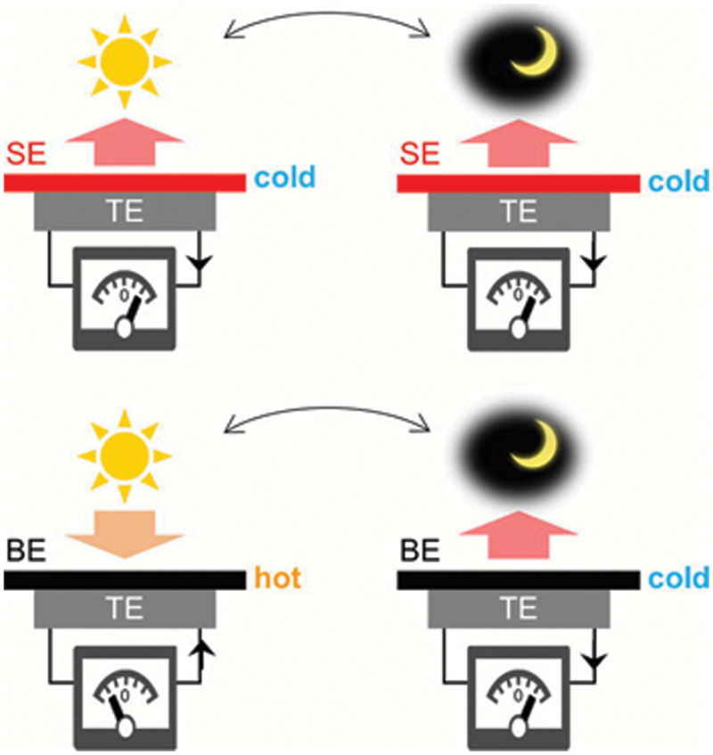
Figure 22: Conceptual drawing of thermoelectric devices having a wavelength-selective emitter and a broadband emitter (BE) on the top. Reproduced with permission from reference [78]
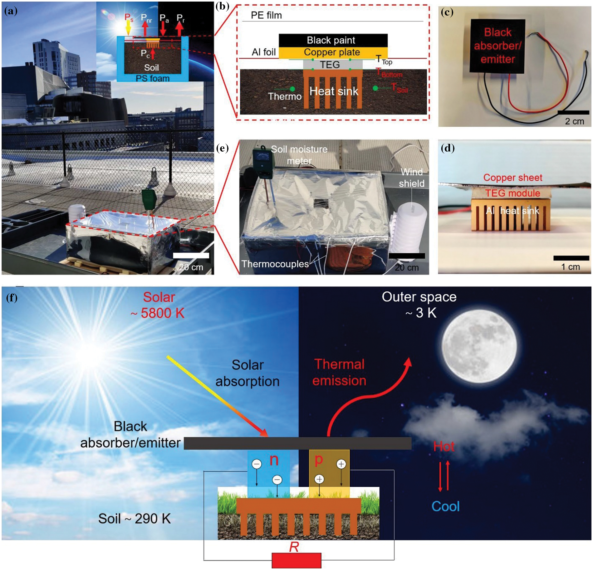
Figure 23: Experimental investigation of a 24-h TEG based energy harvesting system. (a) Photography showing a 24-h TEG device in rooftop testing at Northeastern University, Boston, MA. The inset depicts the schematic of the cross-section and the energy flows between TEG, the Sun, the ambient, and the outer space. (b) Schematic of the 24-h TEG module consisting of the black-coated dual-purpose copper plate as both a solar heater and a radiative cooler. The TEG module is connected with the copper plate and heat sink using the thermal compound paste. An aluminum heat sink is inserted into the soil to release the heat during the daytime and absorb it at night. Top (c) and side (d) views of the TEG module. (e) Top view of the device with a soil humidity meter to show the moisture level in the soil, a windshield with a K-type thermocouple inside monitoring the ambient temperature, and thermocouples recording the temperature of the top and bottom surfaces of the TEG module and two different locations in the soil. (f) Schematic of exhibiting the operational principle of a 24-h TEG based energy harvesting system between the Sun, outer space, and soil. Reproduced with permission from reference [81]
An alternative approach involves utilizing a combination of a coating and phase change materials in building walls. In this approach, the coating is applied to one end of TEGs, while the other end is equipped with phase change materials. In this case, the coating only needs to fulfil the requirement of absorbing heat under sunlight. By optimizing the coating’s properties, such as high absorptivity within the solar band, the TEGs can efficiently capture and convert solar energy into electricity. Simultaneously, at the opposite end of the TEGs, phase change materials are incorporated. As shown in Fig. 24, Byon et al. [82] have developed an energy-harvesting block that incorporates a TEG and utilizes a PCM. In their design, the PCM serves to cool the cold end of the TEG during the daytime, while it releases the stored heat energy at night. Fig. 25 illustrates the conceptual application of the TEG-PCM brick wall [83]. Based on experimental findings, the energy-harvesting block demonstrates an average electrical power output of 0.01 W during representative days in both summer and winter seasons. On an extreme representative day, the power output increases to 0.03 W [83]. This cumulative performance results in an overall annual energy generation of 2.075 kWh/m2.
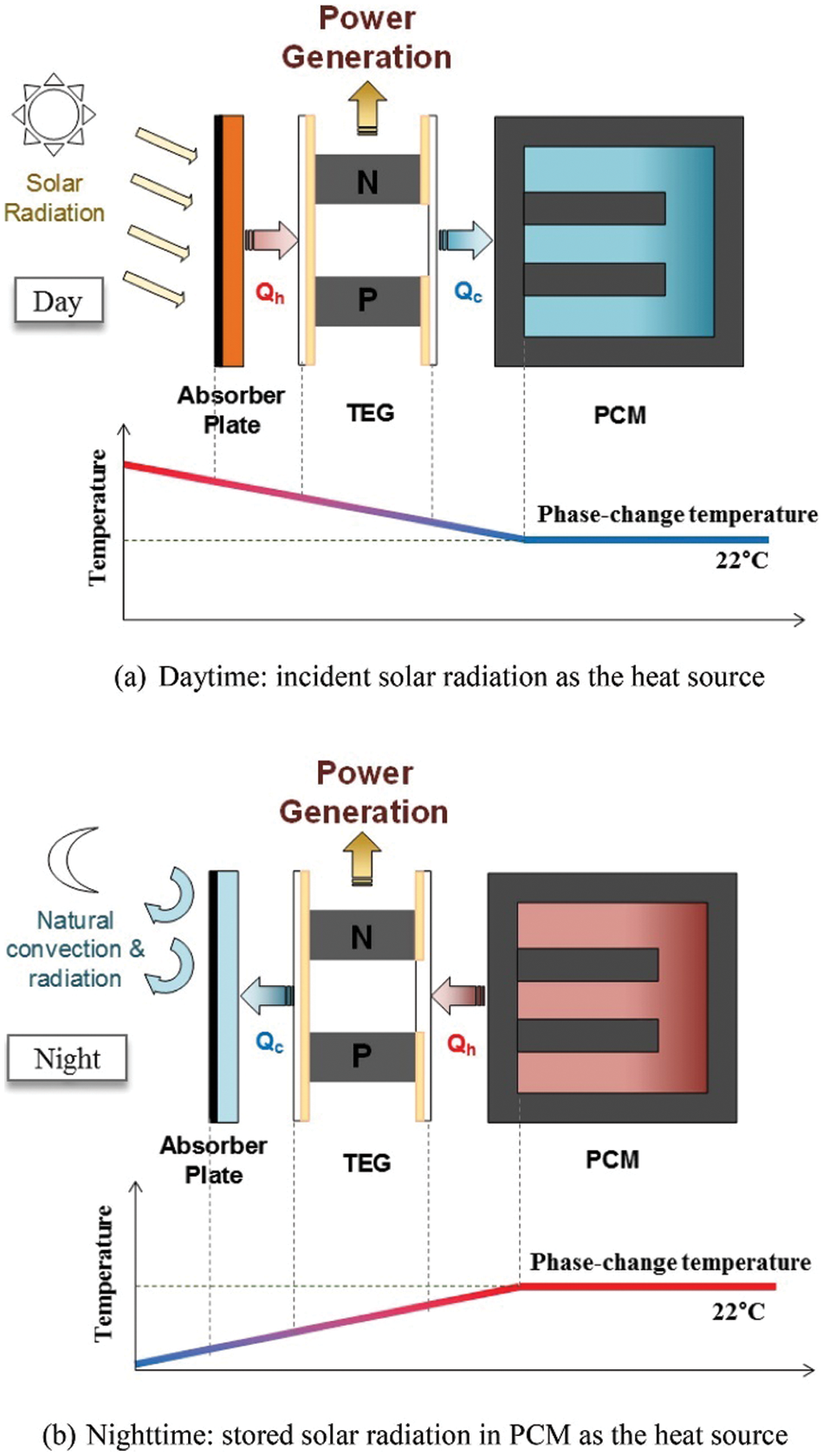
Figure 24: Concept of building integrated energy-harvesting block. Reproduced with permission from reference [82]
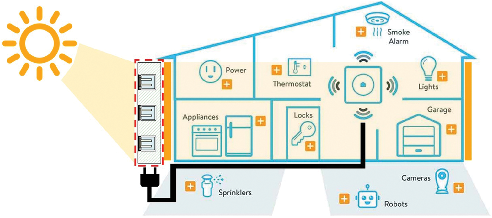
Figure 25: Application of the TEG-PCM brick wall. Reproduced with permission from reference [83]
4.2 Dual-Coating Approaches for Dual-Mode Thermoelectric Generators
In this section, we specifically focus on dual coating approaches aimed at enhancing the performance of thermoelectric generators driven by solar energy and radiative cooling. These approaches involve the use of two distinct coatings, namely a solar selective absorber and a radiative cooler, positioned at each end of the TEG. The goal of employing these dual coatings is to optimize the utilization of solar radiation and radiative cooling, thereby achieving efficient energy conversion.
The system configuration designed by Yu et al. [84] is illustrated in Fig. 26, providing a visual representation of its components and arrangement. The proposed theoretical model predicts a maximum output power of 145 W/m2 under daylight conditions and 65 mW/m2 during darkness. Outdoor experiments show that without any thermal management, the observed output powers are 0.8 mW/m2 during the nighttime and 91 mW/m2 during the daytime. These findings highlight the potential for significant power enhancement and overall system efficiency improvement throughout the day-and-night cycle by implementing thermal management strategies. Lv et al. [85] incorporated a parabolic trough solar concentrator and a PE film into the system, as depicted in Fig. 27. Outdoor experimental observations revealed that the model achieved a peak temperature difference of approximately 4.5°C, with a maximum open-circuit voltage reaching around 56 mV.
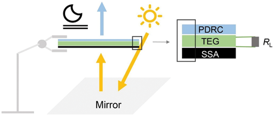
Figure 26: Schematic of the outdoor experimental setup. Adapted from reference [84]
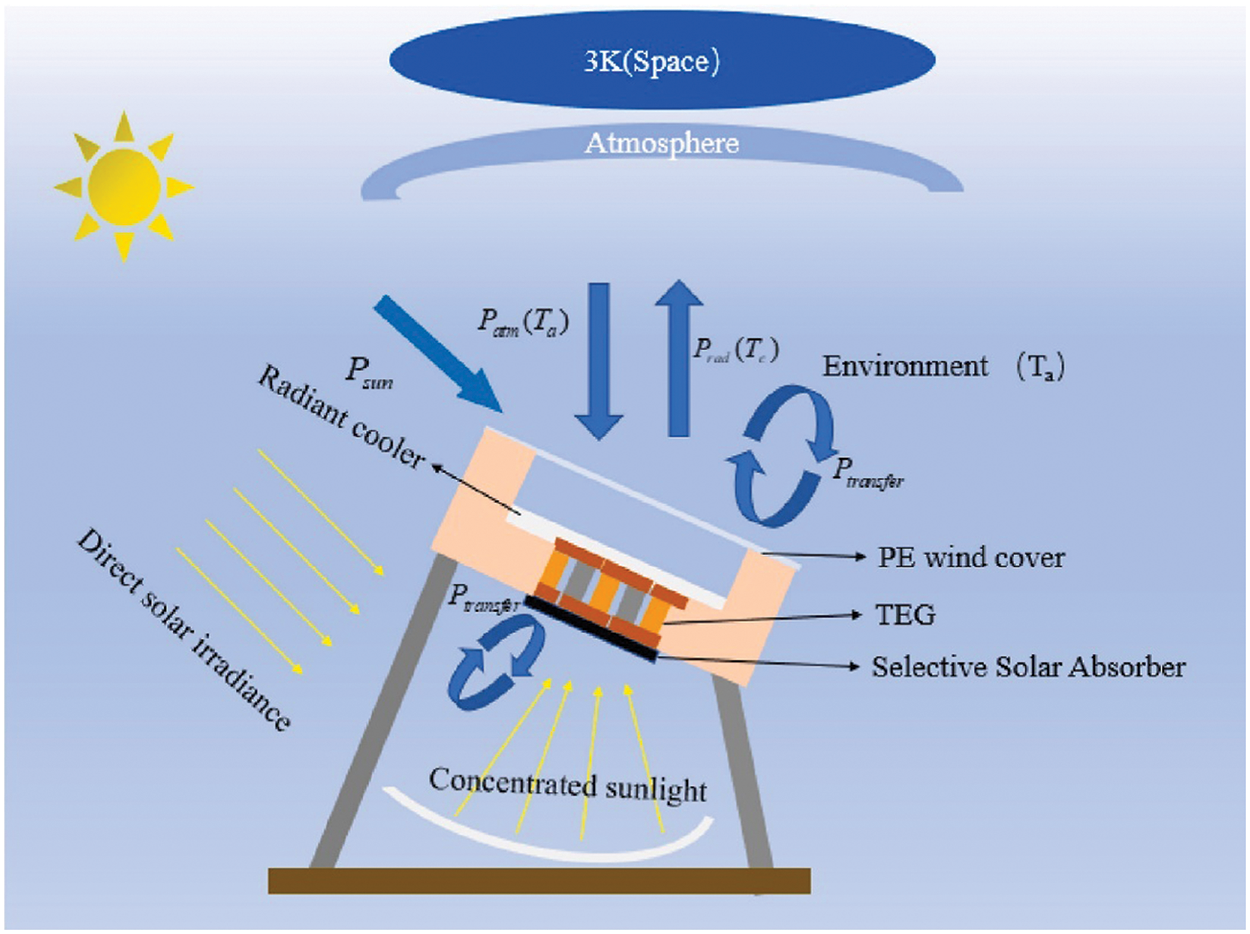
Figure 27: Structure of the designed concentrating RC-TEG model. Reproduced with permission from reference [85]
4.3 Comprehensive Discussions on Dual-Mode Thermoelectric Generators
In this section, we provide a comprehensive overview of dual-mode thermoelectric generators, and Table 3 summarizes the key aspects of DM-TEGs. These systems combine the utilization of solar radiation during the day and radiative cooling at night for enhanced energy conversion. We discuss their system performance, challenges, and potential applications.
The performance of DM-TEGs is crucial for their effectiveness. Factors such as solar energy absorption, radiative cooling efficiency, thermal management, and electrical power output play a significant role. One-coating and dual-coating approaches have been explored to optimize these parameters, resulting in promising power densities and voltage outputs. Despite advancements, there are challenges to address, including coating design, thermal management, scalability, and cost-effectiveness. However, DM-TEGs hold potential for applications in off-grid power generation, building integration, and portable electronics. They offer sustainable and environmentally friendly solutions, contributing to energy savings and reducing greenhouse gas emissions.
In summary, DM-TEGs driven by solar energy and radiative cooling offer continuous power generation. Ongoing research is needed to overcome challenges and optimize their performance for practical applications in various sectors.
5 Future Perspectives: Advancements and Emerging Applications
Unlocking the full potential of thermoelectric generators requires a forward-looking approach towards advancements and emerging applications. This chapter explores the future perspectives that encompass system configuration, advanced management techniques, model development, utilization of new materials, and expanding applications. By embracing these future directions, we pave the way for more efficient operation, enhanced control, and the realization of TEGs as a sustainable energy solution for diverse industries and sectors.
System configuration plays a crucial role in facilitating experimental investigations and exploring new research directions with promising prospects. It involves the exploration of innovative system configurations, integration with other energy conversion technologies, and optimization of overall system performance to maximize energy conversion efficiency and reliability.
One example of an innovative configuration is the combination of TEGs with concentrated radiative cooling. This configuration presents exciting research opportunities, such as the design, analysis, and optimization of combined concentrated solar-driven TEGs and concentrated radiative cooling-driven TEGs. These integrated systems hold great potential for enhanced energy conversion efficiency. To ensure efficient operation and control of such integrated systems, advanced management techniques and the development of novel numerical models are required. These techniques and models enable effective system management and facilitate the optimization of energy conversion processes.
By exploring new system configurations, integrating different energy conversion technologies, and employing advanced management techniques, researchers can advance the field of thermoelectric energy conversion, leading to improved overall system performance, energy efficiency, and reliability.
To maximize the performance of integrated TEG systems, the implementation of advanced management strategies is crucial. Ongoing research focuses on exploring advanced thermal management strategies under concentrated sunlight conditions. These strategies include microchannel cooling, heat pipes, phase change materials, and other innovative cooling methods that effectively dissipate excess heat and maintain optimal operating temperatures. Additionally, the development of sophisticated control algorithms, smart energy management systems, and advanced thermal management techniques is essential. By utilizing these advancements, optimal utilization of available thermal gradients, efficient power generation, and effective heat dissipation can be achieved. This, in turn, leads to improved overall system efficiency and reliability. The continuous development of advanced management strategies ensures that TEG systems can operate optimally, even under challenging environmental conditions, and contribute to sustainable energy solutions.
Accurate modelling plays a crucial role in understanding and predicting the behaviour of TEGs in complex and dynamic environments, accounting for variations and transient conditions. The refinement and development of more precise numerical models are essential to consider non-uniform temperature distributions, localized effects, material anisotropy, and complex heat transfer mechanisms within TEGs. These advancements enable a comprehensive understanding of TEG behaviour and facilitate more accurate predictions in real-world scenarios.
To achieve this, the development of advanced resistance thermal models is required, incorporating capacitance to accurately predict system performance in the presence of dynamic variations in external conditions. Furthermore, coupling numerical simulation software such as ANSYS and COMSOL can provide enhanced visualization and enable the development of advanced models using user-defined functions tailored to specific scenarios. This integration of simulation tools allows for a comprehensive understanding of TEG behaviour and facilitates the creation of more accurate and reliable models.
New materials are currently under development to enhance the solar absorbance and improve the radiative cooling emittance of TEG coatings. These ongoing exploration and development of advanced materials aim to optimize the conversion of solar radiation into thermal energy and improve heat dissipation from TEG systems. Researchers are exploring innovative approaches such as nanotechnology and surface modifications to achieve higher optical properties, thermal conductivity, and stability [86,87]. The goal is to identify cost-effective and scalable materials that can revolutionize energy harvesting and cooling technologies in TEG systems.
Thermoelectric generators offer diverse applications in various fields, and their future prospects continue to expand. Here are some notable applications:
1. Combined heat and power systems: TEGs integrated into combined heat and power systems enable simultaneous electricity generation and utilization of waste heat. This approach achieves high energy efficiency and reduces environmental impact by maximizing the utilization of available energy resources.
2. Portable electronic devices: TEGs can power portable electronic devices, providing sustainable and autonomous energy sources. This application eliminates the need for traditional batteries and enables self-sufficient power supply for devices like LED lights and mobile phones, enhancing their sustainability and reducing reliance on conventional power sources.
3. Building integration: Incorporating thermoelectric modules into building materials, such as roofs, facades, or windows, holds great potential for enhancing the energy efficiency of buildings. By harnessing heat and converting it into usable electricity, TEGs integrated into building phase change materials reduce the reliance on conventional active cooling systems and contribute to sustainable building design.
4. Off-grid power generation: TEGs offer a promising solution for off-grid power generation, particularly in remote or resource-constrained areas. TEGs can provide reliable and sustainable electricity in locations where conventional power infrastructure is limited or inaccessible, enabling energy independence and improving the quality of life in these regions.
In conclusion, the future of TEGs lies in advancements and emerging applications. System configuration, advanced management techniques, model development, utilization of new materials, and expanding applications all contribute to the continuous improvement and broader adoption of TEG technology in various sectors. Continued research and development efforts in these areas will drive the realization of the full potential of TEGs and their integration into sustainable energy systems.
Harvesting renewable energy from the sun and deep space to continuously produce clean electricity provides a promising solution for addressing the energy crisis and achieving a low-carbon future. Thermoelectric generators play a crucial role in collecting solar energy and/or cooling power from deep space, enabling the production of clean electric energy that is environmentally friendly, reliable, and quiet and vibration-free. This green energy collection technology has wide-ranging applications and can particularly benefit areas with limited power infrastructure, as well as microelectronic and wearable devices. Directly converting solar energy or utilizing radiative cooling power offers unique advantages for renewable energy generation and passive cooling. In this comprehensive review, the system configurations, performance, and applications of TEGs driven by solar and/or radiative cooling are thoroughly examined. Various strategies, including non-concentrating, optical-concentrating, and thermal-concentrating approaches for solar-driven thermoelectric generators, as well as non-concentrating radiative cooling-driven thermoelectric generators and dual-mode thermoelectric generators, are comprehensively covered. Furthermore, the review explores the materials used for solar absorbers and radiative coolers, and analyses simulation techniques, energy storage management, and the diverse applications of thermoelectric generators driven by solar and/or radiative cooling. The importance of advanced thermal management techniques is highlighted, as they play a pivotal role in effectively dissipating the considerable heat flux and maintaining stable output power. Additionally, the integration of TEGs with combined heat and power systems is identified as a promising application. TEGs also hold the potential to serve as charging sources for electronic devices. The integration of thermoelectric modules into building materials presents a significant opportunity to improve the energy efficiency of buildings. This comprehensive review provides valuable insights into a novel mode of energy collection that harnesses solar energy and deep space cooling. It serves as a reference to enhance the efficiency of environmental energy collection, reduce costs, and expand the range of applications. Moreover, the review sheds light on the current limitations and knowledge gaps in the understanding of thermoelectric generators driven by solar energy and/or radiative cooling. It underscores the importance of further research and development in this field to fully unlock the potential of these generators and contribute to a more sustainable and efficient energy future.
Acknowledgement: Acknowledgment and warmest thanks are extended to The Hong Kong Polytechnic University (PolyU) for their support. As a Ph.D. student in the Department of Building Environment and Energy Engineering Affiliated with PolyU, my research endeavors have been financially supported by this esteemed institution. I would also like to express my sincere gratitude to my Ph.D. supervisor, Lin Lu, for her invaluable guidance and unwavering support. Her contributions to data collection and manuscript writing have been significant.
Funding Statement: The work described in this paper was supported by the Hong Kong Polytechnic University through Projects of RCRE (Project No. 1-BBEG) and a grant from the NSFC/RGC Joint Research Scheme sponsored by the Research Grants Council of Hong Kong and the National Natural Science Foundation of China (Project No. N_PolyU513/18).
Author Contributions: Study conception and design: Jinglong Wang, Lin Lu, Kai Jiao; data collection: Jinglong Wang; analysis and interpretation of results: Jinglong Wang, Lin Lu, Kai Jiao; draft manuscript preparation: Jinglong Wang. All authors reviewed the results and approved the final version of the manuscript.
Availability of Data and Materials: The data used in this review were obtained from publicly available sources, as cited in the references section. No new data were generated or analyzed in this review.
Ethics Approval: Not applicable.
Conflicts of Interest: The authors declare that they have no conflicts of interest to report regarding the present study.
References
1. M. Han, L. Lu, and B. Sun, “Overall energy performance of building-integrated bifacial photovoltaic sunshades with different installation and building parameters in hot and humid regions,” Sol. Energy, vol. 275, pp. 1–10, Jun. 2024. doi: 10.1016/j.solener.2024.112619. [Google Scholar] [CrossRef]
2. R. S. Anand et al., “Super-long gravity heat pipe for geothermal energy exploitation—A comprehensive review,” Renew. Sustain. Energy Rev., vol. 193, pp. 1–26, Apr. 2024. doi: 10.1016/j.rser.2024.114286. [Google Scholar] [CrossRef]
3. X. Du et al., “Wake galloping piezoelectric-electromagnetic hybrid ocean wave energy harvesting with oscillating water column,” Appl. Energy, vol. 353, no. 1, pp. 1–10, Jan. 2024. doi: 10.1016/j.apenergy.2023.122081. [Google Scholar] [CrossRef]
4. S. Wang, J. Shi, W. Yang, and Q. Yin, “High and low frequency wind power prediction based on transformer and BiGRU-attention,” Energy, vol. 288, no. 6, pp. 1–30, Jan. 2024. doi: 10.1016/j.energy.2023.129753. [Google Scholar] [CrossRef]
5. R. Xu, X. Tan, H. Wang, Z. Zhu, X. Lu and C. Li, “Stability of hydropower units under full operating conditions considering nonlinear coupling of turbine characteristics,” Renew Energy, vol. 223, no. 10, pp. 1–15, Mar. 2024. doi: 10.1016/j.renene.2024.120009. [Google Scholar] [CrossRef]
6. X. Chen, C. Zhang, X. Chen, Z. Peng, H. Gao and X. Gong, “Performance analysis of a novel biomass gasification system coupled to a coal-fired power plant based on heat and water recovery,” Energy Convers. Manag., vol. 299, no. 9, pp. 1–13, Jan. 2024. doi: 10.1016/j.enconman.2023.117822. [Google Scholar] [CrossRef]
7. E. Velmre, “Thomas Johann Seebeck and his contribution to the modern science and technology,” in Proc. BEC, Oct. 2010, pp. 17–24. [Google Scholar]
8. Y. Chen et al., “Dynamic reconfiguration for TEG systems under heterogeneous temperature distribution via adaptive coordinated seeker,” Prot. Control Mod. Power Syst., vol. 7, no. 3, pp. 1–18, Jul. 2024. doi: 10.1186/s41601-022-00259-6. [Google Scholar] [CrossRef]
9. M. Feng et al., “An overview of environmental energy harvesting by thermoelectric generators,” Renew. Sustain. Energy Rev., vol. 187, no. 9, pp. 1–29, Nov. 2024. doi: 10.1016/j.rser.2023.113723. [Google Scholar] [CrossRef]
10. M. Z. Kazim et al., “DFT study of optoelectronic and thermoelectric properties of cubic Ba2ZrMO6 (M = Ce, Ti) double perovskites,” J. Solid State Chem., vol. 315, pp. 1–9, Nov. 2022. doi: 10.1016/j.jssc.2022.123419. [Google Scholar] [CrossRef]
11. G. Nie et al., “High performance thermoelectric module through isotype bulk heterojunction engineering of skutterudite materials,” Nano Energy, vol. 66, pp. 1–10, Dec. 2019. doi: 10.1016/j.nanoen.2019.104193. [Google Scholar] [CrossRef]
12. G. Muthu, S. Thulasi, V. Dhinakaran, and T. Mothilal, “Performance of solar parabolic dish thermoelectric generator with PCM,” Mater. Today: Proc., vol. 37, pp. 929–933, Jul. 2020. doi: 10.1016/j.matpr.2020.06.123. [Google Scholar] [CrossRef]
13. F. H. Sun et al., “Review of current ZT > 1 thermoelectric sulfides,” J. Materiomics, vol. 10, no. 1, pp. 218–233, Jan. 2024. doi: 10.1016/j.jmat.2023.05.011. [Google Scholar] [CrossRef]
14. R. Zhang, J. Cai, T. Zhang, and Z. Shi, “Performance analysis and optimization of a TEG-based compression hydrogen storage waste heat recovery system,” Renew. Energy, vol. 219, pp. 1–14, Dec. 2023. doi: 10.1016/j.renene.2023.119521. [Google Scholar] [CrossRef]
15. M. Asaduzzaman, M. H. Ali, N. A. Pratik, and N. Lubaba, “Exhaust heat harvesting of automotive engine using thermoelectric generation technology,” Energy Convers. Manag., vol. 19, no. 12, pp. 1–14, Jul. 2023. doi: 10.1016/j.ecmx.2023.100398. [Google Scholar] [CrossRef]
16. Y. Rao et al., “Fabrication and characterization of a thermoelectric generator with high aspect ratio thermolegs for electrically active implants,” Adv. Mater. Technol., vol. 9, no. 1, pp. 1–9, Nov. 2023. doi: 10.1002/admt.202301157. [Google Scholar] [CrossRef]
17. H. Cho et al., “Milliwatt-scale body-heat harvesting using stretchable thermoelectric generators for fully untethered, self-sustainable wearables,” ACS Energy Lett., vol. 8, no. 6, pp. 2585–2594, May 2023. doi: 10.1021/acsenergylett.3c00243. [Google Scholar] [CrossRef]
18. B. Wu et al., “Stretchable thermoelectric generators with enhanced output by infrared reflection for wearable application,” J. Chem. Eng., vol. 453, no. 4, pp. 1–11, Feb. 2023. doi: 10.1016/j.cej.2022.139749. [Google Scholar] [CrossRef]
19. B. Wu, Y. Guo, C. Hou, Q. Zhang, Y. Li and H. Wang, “From carbon nanotubes to highly adaptive and flexible high-performance thermoelectric generators,” Nano Energy, vol. 89, pp. 1–10, Nov. 2021. doi: 10.1016/j.nanoen.2021.106487. [Google Scholar] [CrossRef]
20. D. Yuan, W. Jiang, A. Sha, J. Xiao, W. Wu and T. Wang, “Technology method and functional characteristics of road thermoelectric generator system based on Seebeck effect,” Appl. Energy, vol. 331, pp. 1–21, Feb. 2023. doi: 10.1016/j.apenergy.2022.120459. [Google Scholar] [CrossRef]
21. F. Tohidi, S. G. Holagh, and A. Chitsaz, “Thermoelectric generators: A comprehensive review of characteristics and applications,” Appl. Therm. Eng., vol. 201, no. 9, pp. 1–44, Jan. 2022. doi: 10.1016/j.applthermaleng.2021.117793. [Google Scholar] [CrossRef]
22. M. A. Zoui, S. Bentouba, J. G. Stocholm, and M. Bourouis, “A review on thermoelectric generators: Progress and applications,” Energies, vol. 13, no. 14, pp. 1–32, Jul. 2020. doi: 10.3390/en13143606. [Google Scholar] [CrossRef]
23. K. Karthick, S. Suresh, M. M. M. Hussain, H. M. Ali, and C. S. S. Kumar, “Evaluation of solar thermal system configurations for thermoelectric generator applications: A critical review,” Sol. Energy, vol. 188, no. 1, pp. 111–142, Aug. 2019. doi: 10.1016/j.solener.2019.05.075. [Google Scholar] [CrossRef]
24. S. Shoeibi, H. Kargarsharifabad, M. Sadi, A. Arabkoohsar, and S. A. A. Mirjalily, “A review on using thermoelectric cooling, heating, and electricity generators in solar energy applications,” Sustain. Energy Technol. Assess., vol. 52, no. 1, pp. 1–25, Aug. 2022. doi: 10.1016/j.seta.2022.102105. [Google Scholar] [CrossRef]
25. X. Zhu, Y. Yu, and F. Li, “A review on thermoelectric energy harvesting from asphalt pavement: Configuration, performance and future,” Constr Build. Mater., vol. 228, no. 4, pp. 1–13, Dec. 2019. doi: 10.1016/j.conbuildmat.2019.116818. [Google Scholar] [CrossRef]
26. A. Elghool, F. Basrawi, T. K. Ibrahim, K. Habib, H. Ibrahim and D. M. N. D. Idris, “A review on heat sink for thermo-electric power generation: Classifications and parameters affecting performance,” Energy Convers. Manag., vol. 134, no. 8, pp. 260–277, Feb. 2016. doi: 10.1016/j.enconman.2016.12.046. [Google Scholar] [CrossRef]
27. S. S. Indira et al., “A review on various configurations of hybrid concentrator photovoltaic and thermoelectric generator system,” Sol. Energy, vol. 201, no. 8, pp. 122–148, May 2020. doi: 10.1016/j.solener.2020.02.090. [Google Scholar] [CrossRef]
28. U. A. Saleh, M. A. Johar, S. A. B. Jumaat, M. N. Rejab, and W. A. W. Jamaludin, “Evaluation of a PV-TEG hybrid system configuration for an improved energy output: A review,” Int. J. Renew. Energy Dev., vol. 10, no. 2, pp. 385–400, May 2021. doi: 10.14710/ijred.2021.33917. [Google Scholar] [CrossRef]
29. M. Sheikholeslami, Z. Khalili, and L. Momayez, “Efficiency improvement of ternary nanofluid within a solar photovoltaic unit combined with thermoelectric considering environmental analysis,” Environ. Technol. Innov., vol. 32, no. 2, pp. 1–13, Nov. 2023. doi: 10.1016/j.eti.2023.103315. [Google Scholar] [CrossRef]
30. M. Sheikholeslami and Z. Khalili, “Investigation of solar photovoltaic cell utilizing hybrid nanofluid confined jet and helical fins for improving electrical efficiency in existence of thermoelectric module,” Appl. Therm. Eng., vol. 234, no. 15, pp. 1–18, Nov. 2023. doi: 10.1016/j.applthermaleng.2023.121329. [Google Scholar] [CrossRef]
31. Y. He, Y. B. Tao, C. Y. Zhao, and X. K. Yu, “Structure parameter analysis and optimization of photovoltaic-phase change material-thermoelectric coupling system under space conditions,” Renew. Energy, vol. 200, no. 8, pp. 320–333, Nov. 2022. doi: 10.1016/j.renene.2022.09.129. [Google Scholar] [CrossRef]
32. R. P. Kandi, M. M. Sudharmini, A. Suryan, and S. Nižetić, “State of the art and future prospects for TEG-PCM systems: A review,” Energy Sustain. Dev., vol. 74, no. 6, pp. 328–348, Jun. 2023. doi: 10.1016/j.esd.2023.04.012. [Google Scholar] [CrossRef]
33. S. Lv et al., “Study on a high-performance solar thermoelectric system for combined heat and power,” Energy Convers. Manag., vol. 143, pp. 459–469, Jul. 2017. doi: 10.1016/j.enconman.2017.04.027. [Google Scholar] [CrossRef]
34. S. Lv et al., “Study of different heat exchange technologies influence on the performance of thermoelectric generators,” Energy Convers. Manag., vol. 156, pp. 167–177, Jan. 2018. doi: 10.1016/j.enconman.2017.11.011. [Google Scholar] [CrossRef]
35. G. Li et al., “Performance analysis on a solar concentrating thermoelectric generator using the micro-channel heat pipe array,” Energy Convers. Manag., vol. 112, pp. 191–198, Mar. 2016. doi: 10.1016/j.enconman.2016.01.025. [Google Scholar] [CrossRef]
36. S. Lv et al., “High-performance terrestrial solar thermoelectric generators without optical concentration for residential and commercial rooftops,” Energy Convers. Manag., vol. 196, pp. 69–76, Sep. 2019. doi: 10.1016/j.enconman.2019.05.089. [Google Scholar] [CrossRef]
37. M. Zhang et al., “Efficient, low-cost solar thermoelectric cogenerators comprising evacuated tubular solar collectors and thermoelectric modules,” Appl. Energy, vol. 109, pp. 51–59, Sep. 2013. doi: 10.1016/j.apenergy.2013.03.008. [Google Scholar] [CrossRef]
38. H. Li et al., “Spray-on carbon black nanopowder/polyvinylidene fluoride-based solar-thermal–electric generators to power electronic devices,” ACS Appl. Nano Mater., vol. 5, no. 2, pp. 2429–2435, Feb. 2022. doi: 10.1021/acsanm.1c04128. [Google Scholar] [CrossRef]
39. C. C. Maduabuchi, K. A. Ejenakevwe, and C. A. Mgbemene, “Performance optimization and thermodynamic analysis of irreversibility in a contemporary solar thermoelectric generator,” Renew. Energy, vol. 168, pp. 1189–1206, May 2020. doi: 10.1016/j.renene.2020.12.130. [Google Scholar] [CrossRef]
40. A. A. Candadai, V. P. Kumar, and H. C. Barshilia, “Performance evaluation of a natural convective-cooled concentration solar thermoelectric generator coupled with a spectrally selective high temperature absorber coating,” Sol. Energy Mat. Sol. C., vol. 145, pp. 333–341, Feb. 2015. doi: 10.1016/j.solmat.2015.10.040. [Google Scholar] [CrossRef]
41. L. Li, X. Gao, G. Zhang, W. Xie, F. Wang and W. Yao, “Combined solar concentration and carbon nanotube absorber for high performance solar thermoelectric generators,” Energy Convers. Manag., vol. 183, pp. 109–115, Mar. 2018. doi: 10.1016/j.enconman.2018.12.104. [Google Scholar] [CrossRef]
42. C. Li et al., “Effects of environmental factors on the conversion efficiency of solar thermoelectric co-generators comprising parabola trough collectors and thermoelectric modules without evacuated tubular collector,” Energy Convers. Manag., vol. 86, pp. 944–951, Oct. 2014. doi: 10.1016/j.enconman.2014.06.010. [Google Scholar] [CrossRef]
43. P. V. Escobar, D. I. Oyarzun, A. Arias, and A. M. Guzmán, “Experimental study of a hybrid solar thermoelectric generator energy conversion system,” Energy Convers. Manag., vol. 238, no. 1, pp. 1–9, Jun. 2021. doi: 10.1016/j.enconman.2021.113997. [Google Scholar] [CrossRef]
44. Q. Wang, Y. Yao, Z. Shen, M. Hu, and H. Yang, “Concentrated solar power tower systems coupled locally with spectrally selective coatings for enhancement of solar-thermal conversion and economic performance,” Green Energy Resour., vol. 1, no. 1, pp. 1–16, Mar. 2023. doi: 10.1016/j.gerr.2022.100001. [Google Scholar] [CrossRef]
45. D. Kraemer et al., “High-performance flat-panel solar thermoelectric generators with high thermal concentration,” Nat. Mater., vol. 10, no. 7, pp. 532–538, May 2011. doi: 10.1038/nmat3013. [Google Scholar] [PubMed] [CrossRef]
46. D. Kraemer et al., “Concentrating solar thermoelectric generators with a peak efficiency of 7.4%,” Nat. Energy, vol. 1, no. 11, pp. 1–8, Sep. 2016. doi: 10.1038/nenergy.2016.153. [Google Scholar] [CrossRef]
47. L. L. Baranowski, G. J. Snyder, and E. S. Toberer, “Concentrated solar thermoelectric generators,” Energy Environ. Sci., vol. 5, no. 10, pp. 9055–9067, Aug. 2012. doi: 10.1039/C2EE22248E. [Google Scholar] [CrossRef]
48. C. Kim and K. Kim, “Enhancement of solar thermoelectric power generation by optical and thermal management with highly transparent aerogel window,” Sol. Energy Mat. Sol. C., vol. 230, pp. 1–9, Sep. 2021. doi: 10.1016/j.solmat.2021.111224. [Google Scholar] [CrossRef]
49. D. Ji et al., “Geometry optimization of solar thermoelectric generator under different operating conditions via Taguchi method,” Energy Convers. Manag., vol. 238, no. 4, pp. 1–12, Jun. 2021. doi: 10.1016/j.enconman.2021.114158. [Google Scholar] [CrossRef]
50. D. Sun, L. Shen, Y. Yao, H. Chen, S. Jin and H. He, “The real-time study of solar thermoelectric generator,” Appl. Therm. Eng., vol. 119, no. 16, pp. 347–359, Jun. 2017. doi: 10.1016/j.applthermaleng.2017.03.075. [Google Scholar] [CrossRef]
51. Z. Sun et al., “Evaluation of energy recovery potential of solar thermoelectric generators using a three-dimensional transient numerical model,” Energy, vol. 256, pp. 1–11, Oct. 2022. doi: 10.1016/j.energy.2022.124667. [Google Scholar] [CrossRef]
52. D. N. Kossyvakis, C. G. Vossou, C. G. Provatidis, and E. V. Hristoforou, “Computational analysis and performance optimization of a solar thermoelectric generator,” Renew. Energy, vol. 81, no. 1, pp. 150–161, Sep. 2015. doi: 10.1016/j.renene.2015.03.026. [Google Scholar] [CrossRef]
53. R. K. Nayak, S. Ray, S. S. Sahoo, and P. K. Satapathy, “Effect of angle of attack and wind direction on limiting input heat flux for solar assisted thermoelectric power generator with plate fin heat sink,” Sol. Energy, vol. 186, pp. 175–190, Jul. 2019. doi: 10.1016/j.solener.2019.05.010. [Google Scholar] [CrossRef]
54. F. S. Moraes, L. C. Santos, R. N. Alencar, É.V. Sempels, and F. J. Lesage, “Solar thermoelectric generator performance relative to air speed,” Energy Convers. Manag., vol. 99, no. 15, pp. 326–333, Jul. 2015. doi: 10.1016/j.enconman.2015.04.049. [Google Scholar] [CrossRef]
55. F. J. Montero, R. Lamba, A. Ortega, W. Jahn, and A. M. Guzman, “A novel 24-h day-night operational solar thermoelectric generator using phase change materials,” J. Clean. Prod., vol. 296, no. 6, pp. 1–15, May 2021. doi: 10.1016/j.jclepro.2021.126553. [Google Scholar] [CrossRef]
56. N. Miljkovic and E. N. Wang, “Modeling and optimization of hybrid solar thermoelectric systems with thermosyphons,” Sol. Energy, vol. 85, no. 11, pp. 2843–2855, Nov. 2011. doi: 10.1016/j.solener.2011.08.021. [Google Scholar] [CrossRef]
57. M. Ge, Z. Wang, L. Liu, J. Zhao, and Y. Zhao, “Performance analysis of a solar thermoelectric generation (STEG) system with spray cooling,” Energy Convers. Manag., vol. 177, pp. 661–670, Dec. 2018. doi: 10.1016/j.enconman.2018.10.016. [Google Scholar] [CrossRef]
58. E. Bellos and C. Tzivanidis, “Energy and financial analysis of a solar driven thermoelectric generator,” J. Clean. Prod., vol. 264, no. 1, pp. 1–16, Aug. 2020. doi: 10.1016/j.jclepro.2020.121534. [Google Scholar] [CrossRef]
59. B. Y. Ohara and H. Lee, “Exergetic analysis of a solar thermoelectric generator,” Energy, vol. 91, pp. 84–90, Nov. 2015. doi: 10.1016/j.energy.2015.08.030. [Google Scholar] [CrossRef]
60. B. Ohara et al., “Residential solar combined heat and power generation using solar thermoelectric generation,” J. Electron. Mater., vol. 44, no. 6, pp. 2132–2141, Mar. 2015. doi: 10.1007/s11664-015-3702-z. [Google Scholar] [CrossRef]
61. A. P. Raman, W. Li, and S. Fan, “Generating light from darkness,” Joule, vol. 3, no. 11, pp. 2679–2686, Nov. 2019. doi: 10.1016/j.joule.2019.08.009. [Google Scholar] [CrossRef]
62. X. Zhang and Y. S. Ang, “Conceptual design and performance optimization of a nighttime electrochemical system for electric power generation via radiative cooling,” Energy, vol. 242, pp. 1–7, Mar. 2021. doi: 10.1016/j.energy.2021.123034. [Google Scholar] [CrossRef]
63. Z. Shi et al., “Maximizing energy generation: A study of radiative cooling-based thermoelectric power devices,” Energy, vol. 274, pp. 1–12, Jul. 2023. doi: 10.1016/j.energy.2023.127283. [Google Scholar] [CrossRef]
64. Y. Zhang et al., “Effective radiative cooling with ZrO2/PDMS reflective coating,” Sol. Energy Mat. Sol. C., vol. 229, pp. 1–8, Aug. 2021. doi: 10.1016/j.solmat.2021.111129. [Google Scholar] [CrossRef]
65. Y. Ji and S. Lv, “Comprehensive research on a simple and efficient radiative cooling driving thermoelectric generator system for nighttime passive power generation,” Appl. Therm. Eng., vol. 219, no. 1–2, pp. 1–10, Jan. 2023. doi: 10.1016/j.applthermaleng.2022.119560. [Google Scholar] [CrossRef]
66. Z. Zhan et al., “Enhancing thermoelectric output power via radiative cooling with nanoporous alumina,” Nano Energy, vol. 65, pp. 1–7, Nov. 2019. doi: 10.1016/j.nanoen.2019.104060. [Google Scholar] [CrossRef]
67. C. H. Wang, H. Chen, Z. Y. Jiang, and X. X. Zhang, “Design and experimental validation of an all-day passive thermoelectric system via radiative cooling and greenhouse effects,” Energy, vol. 263, no. 6460, pp. 1–6, Jan. 2023. doi: 10.1016/j.energy.2022.125735. [Google Scholar] [CrossRef]
68. C. H. Wang, H. Chen, Z. Y. Jiang, X. X. Zhang, and F. Q. Wang, “Modelling and performance evaluation of a novel passive thermoelectric system based on radiative cooling and solar heating for 24-hour power-generation,” Appl. Energy, vol. 331, no. 7, pp. 1–14, Feb. 2023. doi: 10.1016/j.apenergy.2022.120425. [Google Scholar] [CrossRef]
69. Z. Omair, S. Assawaworrarit, L. Fan, W. Jin, and S. Fan, “Radiative-cooling-based nighttime electricity generation with power density exceeding 100 mW/m2,” iScience, vol. 25, no. 8, pp. 1–10, Aug. 2022. doi: 10.1016/j.isci.2022.104858. [Google Scholar] [PubMed] [CrossRef]
70. B. Zhao, G. Pei, and A. P. Raman, “Modeling and optimization of radiative cooling based thermoelectric generators,” Appl. Phys. Lett., vol. 117, no. 16, pp. 1–8, Oct. 2020. doi: 10.1063/5.0022667. [Google Scholar] [CrossRef]
71. D. Zhao et al., “Radiative sky cooling: Fundamental principles, materials, and applications,” Appl. Phys. Rev., vol. 6, no. 2, pp. 1–41, Apr. 2019. doi: 10.1063/1.5087281. [Google Scholar] [CrossRef]
72. J. Liu, Y. Zhang, D. Zhang, S. Jiao, Z. Zhang and Z. Zhou, “Model development and performance evaluation of thermoelectric generator with radiative cooling heat sink,” Energy Convers. Manag., vol. 216, pp. 1–13, Jul. 2020. doi: 10.1016/j.enconman.2020.112923. [Google Scholar] [CrossRef]
73. J. Liu, J. Zhang, J. Yuan, D. Zhang, J. Xing and Z. Zhou, “Model development and performance evaluation of thermoelectric and radiative cooling module to achieve all-day power generation,” Sol. Energy Mat. Sol. C., vol. 220, pp. 1–13, Jan. 2020. doi: 10.1016/j.solmat.2020.110855. [Google Scholar] [CrossRef]
74. P. Poredoš et al., “Radiative sky cooling thermal concentration with cooling power exceeding one kW per square meter,” Energy Environ. Sci., vol. 17, no. 6, pp. 2336–2355, Feb. 2024. doi: 10.1039/D3EE03214K. [Google Scholar] [CrossRef]
75. M. Dong, L. Zhu, B. Jiang, S. Fan, and Z. Chen, “Concentrated radiative cooling and its constraint from reciprocity,” Opt. Express., vol. 30, no. 1, pp. 275–285, Dec. 2022. doi: 10.1364/OE.445544. [Google Scholar] [PubMed] [CrossRef]
76. L. Zhou et al., “Hybrid concentrated radiative cooling and solar heating in a single system,” Cell Rep. Phys. Sci., vol. 2, no. 2, pp. 1–13, Feb. 2021. doi: 10.1016/j.xcrp.2021.100338. [Google Scholar] [CrossRef]
77. J. Peoples et al., “Concentrated radiative cooling,” Appl. Energy, vol. 310, pp. 1–7, Mar. 2022. doi: 10.1016/j.apenergy.2021.118368. [Google Scholar] [CrossRef]
78. S. Ishii, T. D. Dao, and T. Nagao, “Radiative cooling for continuous thermoelectric power generation in day and night,” Appl. Phys. Lett., vol. 117, no. 1, pp. 1–6, Jul. 2020. doi: 10.1063/5.0010190. [Google Scholar] [CrossRef]
79. J. Wang, L. Lu, J. Chen, and L. Jia, “Parametric analysis and potential evaluation of thermoelectric generator driven by solar energy and radiative sky cooling,” Sol. Energy, vol. 264, no. 7, pp. 1–13, Nov. 2023. doi: 10.1016/j.solener.2023.112071. [Google Scholar] [CrossRef]
80. J. Wang and L. Lu, “Evaluation of heat losses in a non-concentrated solar thermoelectric generator with spectrally selective absorbers,” Heat Transf. Res., vol. 55, no. 14, pp. 73–89, Feb. 2024. doi: 10.1615/HeatTransRes.2024052326. [Google Scholar] [CrossRef]
81. Y. Tian, X. Liu, F. Chen, and Y. Zheng, “Harvesting energy from sun, outer space, and soil,” Sci. Rep., vol. 10, no. 1, pp. 1–9, Dec. 2020. doi: 10.1038/s41598-020-77900-7. [Google Scholar] [PubMed] [CrossRef]
82. Y. S. Byon and J. W. Jeong, “Annual energy harvesting performance of a phase change material-integrated thermoelectric power generation block in building walls,” Energy Build., vol. 228, pp. 1–12, Dec. 2020. doi: 10.1016/j.enbuild.2020.110470. [Google Scholar] [CrossRef]
83. Y. S. Byon and J. W. Jeong, “Phase change material-integrated thermoelectric energy harvesting block as an independent power source for sensors in buildings,” Renew Sustain. Energy Rev., vol. 128, pp. 1–12, Aug. 2020. doi: 10.1016/j.rser.2020.109921. [Google Scholar] [CrossRef]
84. L. Yu, Z. Xi, S. Li, D. Pang, H. Yan and M. Chen, “All-day continuous electrical power generator by solar heating and radiative cooling from the sky,” Appl. Energy, vol. 322, no. 8, pp. 1–8, Sep. 2022. doi: 10.1016/j.apenergy.2022.119403. [Google Scholar] [CrossRef]
85. S. Lv et al., “Comprehensive research on a high performance solar and radiative cooling driving thermoelectric generator system with concentration for passive power generation,” Energy, vol. 275, no. 11, pp. 1–10, Jul. 2023. doi: 10.1016/j.energy.2023.127390. [Google Scholar] [CrossRef]
86. F. Zhang, M. Chen, H. Yan, M. Song, and W. Chen, “In situ oxidizing commercial alloy to achieve selective solar absorption with high-temperature stability,” ACS Appl. Energy Mater., vol. 6, no. 21, pp. 10943–10950, Oct. 2023. doi: 10.1021/acsaem.3c01735. [Google Scholar] [CrossRef]
87. S. Liu, F. Zhang, X. Chen, H. Yan, W. Chen and M. Chen, “Thin paints for durable and scalable radiative cooling,” J. Energy Chem., vol. 90, pp. 176–182, Mar. 2024. doi: 10.1016/j.jechem.2023.11.016. [Google Scholar] [CrossRef]
Cite This Article
 Copyright © 2024 The Author(s). Published by Tech Science Press.
This work is licensed under a Creative Commons Attribution 4.0 International License , which permits unrestricted use, distribution, and reproduction in any medium, provided the original work is properly cited.
 Downloads
 Citation Tools