
 Submit a Paper
 Propose a Special lssue
 Open Access
ARTICLE

Effect of Rigid Pitch Motion on Flexible Vibration Characteristics of a Wind Turbine Blade
1 School of Mechanical Engineering, Anhui University of Science and Technology, Huainan, 232001, China
2 School of Mechanics and Optoelectronic Physics, Anhui University of Science and Technology, Huainan, 232001, China
3 Department of Mechanical Engineering, University of Maryland, Baltimore, MD 21250, USA
4 School of Mechanics and Aerospace Engineering, Southwest Jiaotong University, Chengdu, 610031, China
5 School of Mechanical Engineering, Chongqing University of Technology, Chongqing, 400054, China
* Corresponding Author: Liang Li. Email:
Energy Engineering 2024, 121(10), 2981-3000. https://doi.org/10.32604/ee.2024.048161
Received 29 November 2023; Accepted 24 July 2024; Issue published 11 September 2024
 View Full Text
 Download PDF
Abstract
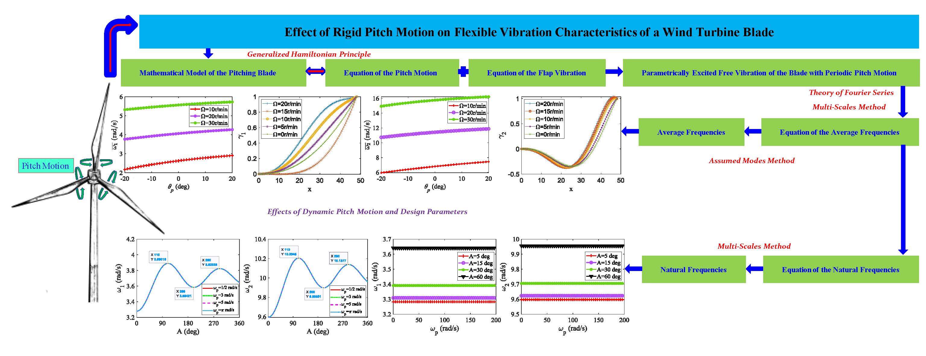
A dynamic pitch strategy is usually adopted to improve the aerodynamic performance of the blade of a wind turbine. The dynamic pitch motion will affect the linear vibration characteristics of the blade. However, these influences have not been studied in previous research. In this paper, the influences of the rigid pitch motion on the linear vibration characteristics of a wind turbine blade are studied. The blade is described as a rotating cantilever beam with an inherent coupled rigid-flexible vibration, where the rigid pitch motion introduces a parametrically excited vibration to the beam. Partial differential equations governing the nonlinear coupled pitch-bend vibration are proposed using the generalized Hamiltonian principle. Natural vibration characteristics of the inherent coupled rigid-flexible system are analyzed based on the combination of the assumed modes method and the multi-scales method. Effects of static pitch angle, rotating speed, and characteristics of harmonic pitch motion on flexible natural frequencies and mode shapes are discussed. It shows that the pitch amplitude has a dramatic influence on the natural frequencies of the blade, while the effects of pitch frequency and pith phase on natural frequencies are little.Graphic Abstract
Keywords
Nomenclature
| A | Amplitude of the pitch motion |
| ωp | Angular frequency of the pitch motion |
| C | Initial phase of the pitch motion |
| W | Flap displacement |
| θt | Pre-twist angle |
| θp | Pitch angle |
| Ω | Rotating speed |
| Modal function | |
| Average frequency | |
| Natural frequency | |
| [K] | Stiffness matrix |
| [M] | Mass matrix |
| r/min | Revolutions per minute |
The study of the vibration characteristics of a blade is essential for the structural design and control of wind turbines. There has been a lot of work on linear or nonlinear vibrations of wind turbine blades. Chopra et al. [1] studied the parametrically excited vibration by simplifying a blade to a rotating rigid body. Larsen et al. [2–4] described a blade as a rotating Euler-Bernoulli beam with a coupled extension-bend-bend vibration and investigated the 1:2 internal resonance, parametric instability, and stochastic stability of the blade. Evans et al. [5] proposed a method to assess the fatigue life of small wind turbine blades operating at higher rotating speeds and subjected to highly unsteady aerodynamic loads and determine the fatigue life of small 5 kW wind turbine blades. Mahri et al. [6,7] used the finite element method (FEM) to calculate the frequency, mode, and forced vibration response of a blade. Liu et al. [8,9] reduced the blade to a composite thin-walled beam, considered the anisotropy of the material, cross-section warping, cone angle, pre-twist angle, and other factors, established a coupled bend-torsion vibration model, studied the flutter, dynamic characteristics, and aeroelastic response, and discussed the effects of fiber ply angle, inlet velocity ratio, pre-twist angle and rotating speed on the aeroelastic stability of the blade. Georgiades et al. [10] considered the factors of variable hub speed rotation, composite thin-walled structure, extension-bend-bend-torsion coupling, mounting angle, and section warping, and established a nonlinear dynamic model of the hub-beam system, where the aerodynamic effect was supplemented in the model, it can be directly applied to the vibration characteristics and stability of the wind wheel system. With the help of the model [10], Warminski et al. [11] employed the generalized Galerkin method to study the coupled extension-bend-torsion vibration of thin-walled composite beams with variable rotating speed and analyzed the dynamic characteristics of the beams including natural frequency, resonance response, and time history. Li et al. [12] introduced structural damping, gravity, inclined installation, and other factors into the model of a blade and analyzed the dynamical characteristics and nonlinear response of the blade. Chen et al. [13] studied the coupled bending-torsional vibration characteristics of the blade based on the transfer matrix method of a multibody system. For floating offshore wind turbines (FOWT), Fu et al. [14–18] used the finite element method and computational fluid dynamics (CFD) method, studied the dynamic characteristics of FOWT under pitch motion of platform, and concluded that the amplitude and frequency of pitch motion have a great influence on power output. Boudounit et al. [19] studied the structural design problem of offshore wind turbine blade spars based on the finite element method and discussed the influence of spars geometry on the blade performance including natural frequencies, modal shapes, and fatigue properties. Lagdani et al. [20] investigated the modal problem of an iced offshore composite wind turbine blade based on the finite element method and analyzed the influence of ice layer thickness and composite materials on natural frequencies and resonance. Previous literature provides a lot of important results and research methods for reference.
The pitch control strategy (the pitch motion is the rotation of a blade around the pitch axis, see Fig. 1; it is a rigid body motion) is usually used to improve the aerodynamic performance of a wind turbine blade. When the influences of the pitch motion are considered: Kallesøe [21] investigated the interaction of pitch, gravity, variable rotating speed, and blade vibration, and proposed a model of a blade with a pitch motion. Wang et al. [22–25] investigated the pitch control strategy to improve the performance of the blade. Seyednia et al. [26] studied the effect of flap trailing edge on airfoil dynamic stall control. Mahmoud et al. [27] performed continuous-time multi-model predictive control for variable-speed variable-pitch wind turbines. Rainone et al. [28] developed a numerical program to determine the pitch law to maximize the performance of vertical axis wind turbines (VAWT). Sagharichi et al. [29] discussed the effect of solids on the performance of variable-pitch VAWT. Li et al. [30] analyzed the pitch optimization of a VAWT blade with a high tip speed ratio. Sendi [31] studied the power output of the variable pitch wind turbine at different wind speeds and discussed the output performance in the case of extreme gusts and long-period wind using blade element theory and the Lagrange equation.
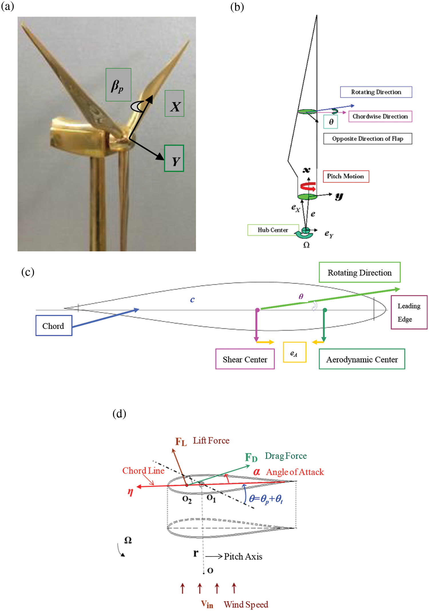
Figure 1: Diagram of (a) a wind turbine, (b) a pitching blade, (c) a section, and (d) section angles
The dynamic pitch motion can introduce a parametrically excited vibration to the blade, affect its flexible vibration characteristics, and may cause instability. However, research works referring to these influences of the pitch motion are rare. This paper aims to present a study on the influences of dynamic pitch motion on the natural bending characteristics of a blade.
In this work, the out-of-plane bend (called flap) which usually has lower frequencies and larger displacement is considered. Fig. 1 shows the schematic diagrams of a wind turbine, a blade, and a cross-section. The angle between the flap direction and the chord line is the section twist angle θ = θt + θp (includes pre-twist angle θt and pitch angle θp, see Fig. 1d). Cartesian right-handed systems [32,33] are employed to describe the configuration of the blade. (xyz) with unit vectors (i, j, k) is a body coordinate system that is rigidly attached to the blade root. The x-axis corresponds to the undeformed elastic axis, the y-axis lies in the plane of rotation, and the z-axis is along the flap direction. (XYZ) with unit vectors (I, J, K) is a global coordinate system with the origin at the center of mass of the hub. The z-axis is aligned with the spin axis backward, and the y-axis is parallel to the y-axis. Small cone angle βp between the rotation plane and the vertical plane is ignored in this work.
The blade is an elongated structure, which can be described as an Euler-Bernoulli beam. After blade deformation, the position vector of the point P (x, y, z) can be calculated as [12,32,33]
where u is the axial displacement of the blade, and w is the flap displacement. The velocity vector of the point P can be obtained from Eq. (1) as
where dots denote derivatives to time t, Ω is the rotating speed of the blade. In the above equation, the equality
where L is the blade length, ρb is the mass density per unit volume, A is the cross-sectional area, and Jp is the rotational inertia of the blade about the pitch axis. The shear strains γxy = 0, γxz = 0 can be assumed from the slender geometric characteristics of the blade. The strain εx satisfies the nonlinear geometric relationship
The distributed external forces and moments acting in the flap direction on blade sections are denoted as Fz and My, respectively. The resultant moment corresponding to the pitch motion is denoted as Mp, which includes the driving moment Ep of the pitch mechanism, aerodynamic moment Ap, and structural damping moment Dp of the pitch mechanism. The structural damping moment can be equivalent to
According to the generalized Hamiltonian principle [34],
Flap Vibration:
i.e.,
Pitch Motion:
where
Flap Vibration:
Based on Fourier’s theory, a complicated signal can be expressed as the superposition of a series of harmonic signals. Therefore, we consider the simple harmonic signal in this paper first.
3 Analysis of Free Vibration of the Inherent Coupled Rigid-Flexible System
Bending stiffness EI changes with time-dependent pith angle θp = θp(t), so the linear modal problem of the blade with a dynamic pitch motion (see Eq. (8)) is different from a routine one (for a beam with constant bending stiffness and mass). A combination method based on the assumed modes method [34] and multi-scales method [35] is proposed to solve the problem, and then the required natural frequencies are calculated. Without loss of generality, we neglect the pre-twist angle θt. The undamped free vibration problem (8) can be rewritten as
Here we assume cos2θp changes periodically with time; it can be expressed to the following Fourier series:
where i is the complex unit, ε is a small parameter. By substituting Eq. (10) into Eq. (9), one obtains the following equation:
Introducing two time scales T0 = t and T1 = εt and assuming:
By substituting Eq. (12) into Eq. (11), one has
When considering the coefficients of ε0 in Eq. (13), one has
If considering the coefficients of ε1 in Eq. (13), one obtains
By assuming
where c.c. represents the conjugate of the preceding function. The approximate boundary conditions are
Exact solutions of Eq. (16) cannot be obtained directly. The assumed modes method is adopted to solve the problem [34]. By taking a family of trail functions that satisfy the geometry boundary conditions
By substituting Eq. (18) into Eq. (16), multiplying
where
The algebraic Eq. (19) has non-zero solutions, so one has
One can derive the ith-order average frequency
In the case of non-resonance, i.e., the pitch frequency and the average frequency have no resonance, the condition of eliminating the long-term term introduces
Both sides of Eq. (22) are multiplied
where
By separating the real and imaginary parts of Eq. (24), one has
After simplification, the following equations are obtained:
Solving
The following formula can be obtained:
By truncating w at ε0, the approximate solution of w is obtained:
where constants C and β0 can be determined by the initial conditions. When there is no resonance between pitch motion and blade vibration, the ith-order flapwise natural frequency of a dynamically pitching blade is
4 Effect of Rigid Pitch Motion on Flexible Natural Characteristics
4.1 Validation of the Theoretical Method
The method proposed in Section 3 is suitable for arbitrary pitching beam structures, not limited to wind turbine blades. In this section, the theoretical method introduced in this work is validated by selecting a rotating cantilever beam model with rectangular cross sections and the following parameters: the length L = 3 m, width b = 0.3 m, height h = 0.2 m, Young’s modulus E = 210 GPa, density ρ = 7.8 × 10³ kg/m3, two principal moments of inertia of cross sectionI1 = bh3/12 and I2 = b3h/12, mass of the cross-section m = ρbh. Results derived from the current method are compared with the results that are obtained based on the single assumed modes method (AMM) and the finite element method (FEM). Here, the time-independent pitch angle is considered because the single AMM and the FEM cannot deal with the dynamic pitch problem. Four polynomial functions Ф1 = (x/L)2, Ф2 = (x/L)3, Ф3 = (x/L)4, Ф4 = (x/L)5 that satisfy the geometric boundary conditions are taken as trail functions in the AMM and current method. The finite element analysis is conducted by using the commercial ANSYS software, where boundary conditions are added to the section x = 0 such that the beam can rotate about the z-axis freely and other displacements of the section x = 0 are fixed to be zero. Solid186 element is used to mesh the structure, where the number of nodes is 621 and the number of elements is 80. Results of the current method are obtained by using the formula
The first three flapwise natural frequencies of the beam at zero rotating speed and zero pitch angle are presented in Table 1. Exact frequencies can be obtained directly in this case. The relative error is defined as (ωMethod − ωExact Result)/ωExact Result to reveal the accuracy of the three methods. One finds from Table 1 that the results of the three methods coincide with the exact results well, especially for the AMM results. Results derived from the current method coincide with exact results well even though the accuracy of the current method is a little bit lower than those of another two methods; the current method provides an effective tool to solve the natural vibration characteristics of a dynamically pitching blade or beam. The first three flapwise frequencies with unit Hz and mode shapes which are obtained from FEM are shown in Fig. 2.
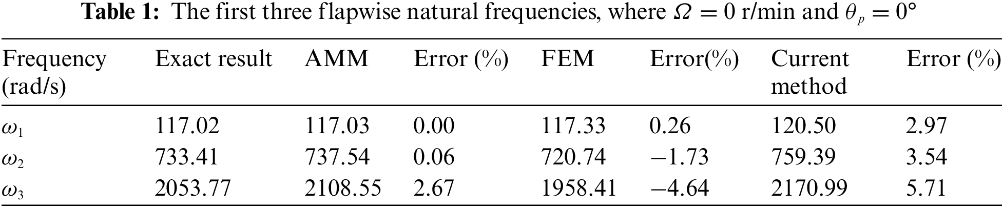
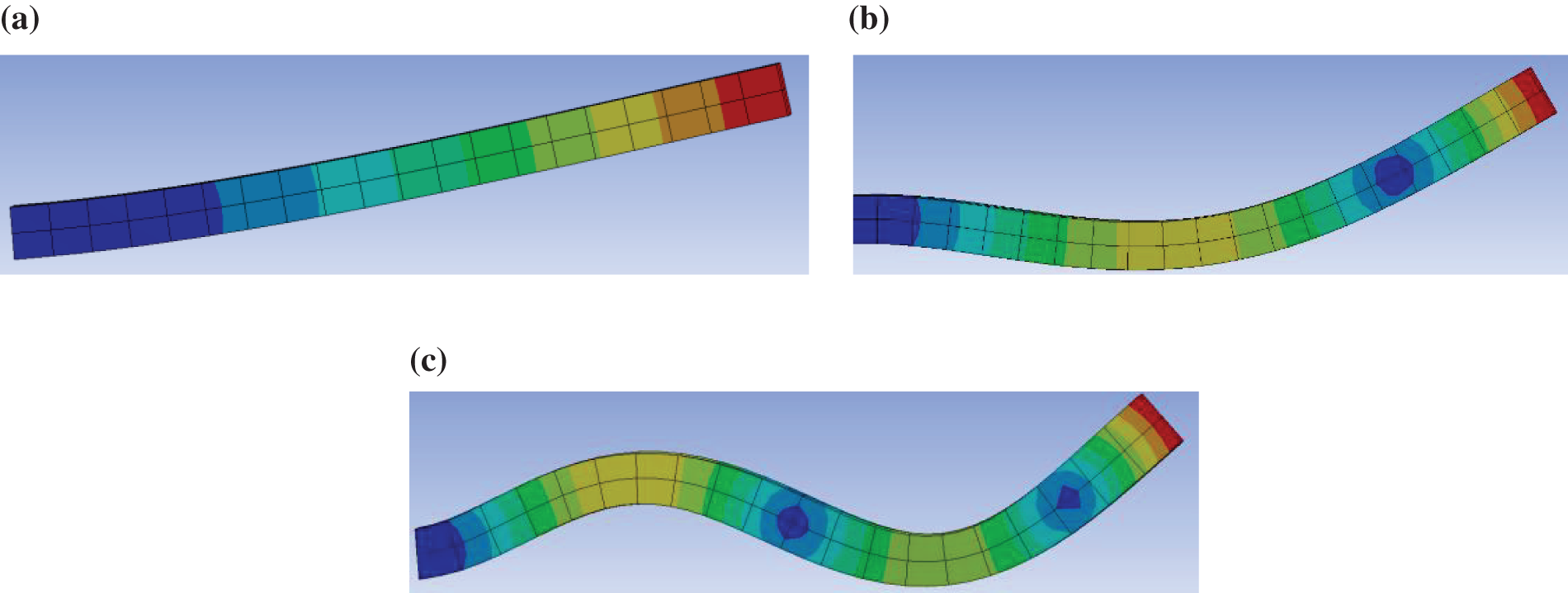
Figure 2: The (a) first-order, (b) second-order, and (c) third-order modal functions
The first three flapwise natural frequencies of the beam with rotating speed Ω = 150 r/min and zero pitch angle are illustrated in Table 2, while exact frequencies can not be calculated directly in this case. Results obtained from the current method are compared with AMM results and FEM results. The relative error is defined as (ωCurrent Method − ωOther Method)/ωOther Method to reveal the accuracy of the current method. It shows that the current results coincide with the AMM results very well. When the current method is compared with the FEM, there is a little bit higher error occurs at the third frequency due to the lower accuracy of both the FEM and current method at higher modes, see Table 1.
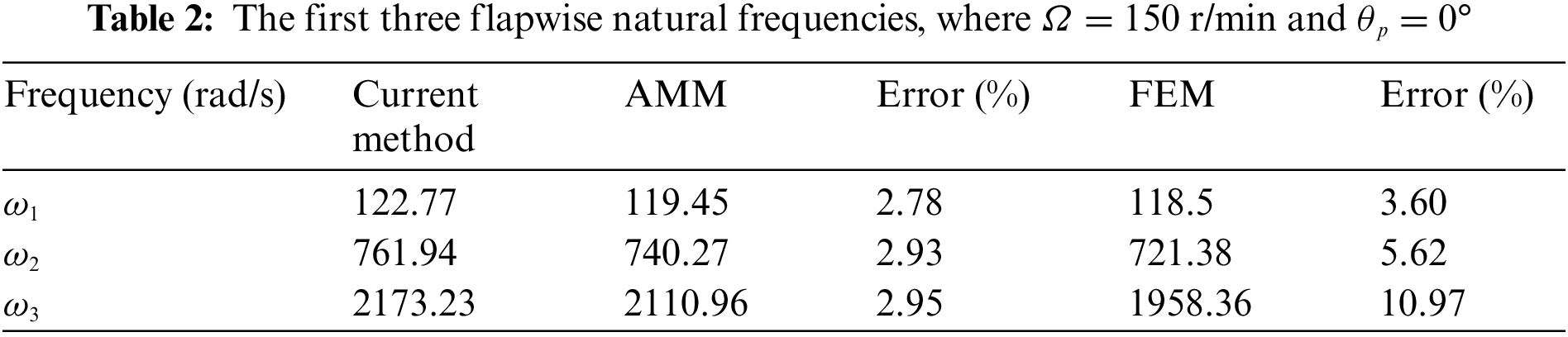
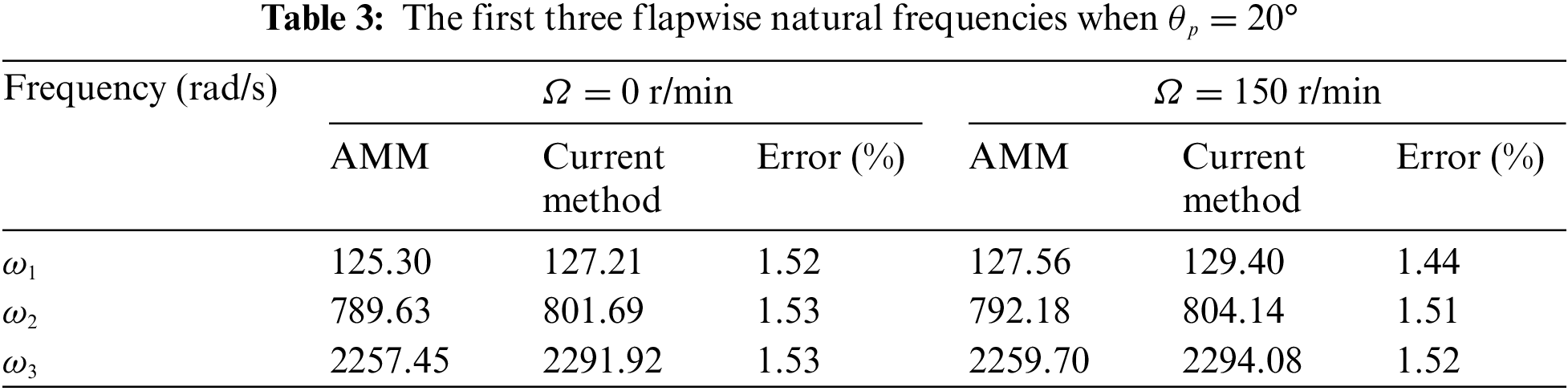
Table 3 provides the first three flapwise natural frequencies of the beam with a constant pitch angle θp = 20° at two different rotating speeds Ω = 0 and Ω = 150 r/min. The FEM can not be used to calculate frequencies in this case. The current results are compared with the AMM results, where the relative error is defined as (ωCurrent Method − ωAMM)/ωAMM. One finds from Table 3 that results derived from the two methods coincide with each other pretty well.
4.2 Effect of Rigid Pitch Motion on Flexible Natural Characteristics
Take the megawatt (MW) wind turbine blade in reference [12] as an example, where distributions of chord length, thickness, and moments of inertia are shown in Fig. 3. Blade length L = 48 m, elastic modulus E is 30 GPa, blade density ρb = 1.8 × 10³ kg/m3, bias (eX, eY) = (0.035, 0.035) × L. Four polynomial functions Ф1 = (x/L)2, Ф2 = (x/L)3, Ф3 = (x/L)4, Ф4 = (x/L)5 that satisfy the geometric boundary conditions are taken as trail functions. The accuracy of the results is validated by the AMM results, where two different rotating speeds Ω = 0 and Ω = 15 r/min are taken. The first three flapwise natural frequencies of the blade with a constant pitch angle θp = 20° are shown in Table 4. It reveals that results derived from the two methods coincide pretty well.
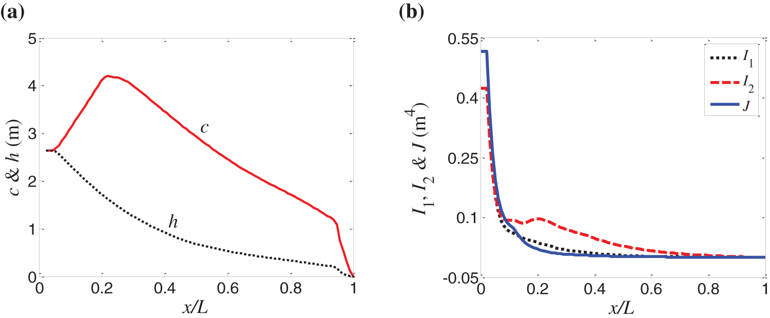
Figure 3: Distributions of (a) the chord length c, thickness h, and (b) three moments of inertia I1, I2, and J

Influences of constant pitch angles on average frequencies and modal functions of the blade are studied first. The first three average frequencies at three different rotating speeds 10, 20, and 30 r/min are presented in Fig. 4. One finds that average frequencies increase with increasing rotating speed, which is because increasing rotating speed can increase the blade stiffness through centrifugal force, which coincides with results in [36–38]; the variation of pitch angle also changes the natural frequencies of the blade.
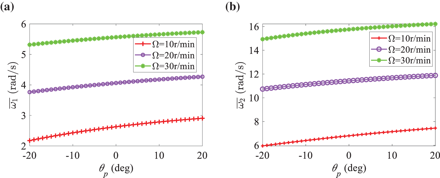
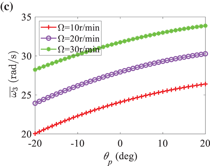
Figure 4: Effect of pitch angle on the average frequency at different rotating speeds: (a) first-order frequency; (b) second-order frequency; (c) third-order frequency
Effects of rotating speed on the first three modal functions are presented in Fig. 5 by selecting a fixed pitch angle θp = 2° and five different rotating speeds Ω = 0, 5, 10, 15, and 20 r/min. The value of each modal function at the blade tip has been set to 1. It reveals that the rotating speed has dramatic influences on modal functions. Increasing the rotating speed makes the first-order and third-order modal shapes steeper, while it is contrary to the second-order modal shape. Influences of pitch angle θp on the first three modal functions are given in Fig. 6 by taking a fixed rotating speed Ω = 15 r/min and five different pitch angles θp = −10°, −5°, 0°, 5°, and 10°. One finds that the influence of pitch angle on each modal function is very small. The natural characteristics of a blade at special pitch rules are discussed in the following part.

Figure 5: Influences of rotating speed Ω on (a) first-order, (b) second-order, and (c) third-order modal functions, where θp = 2°
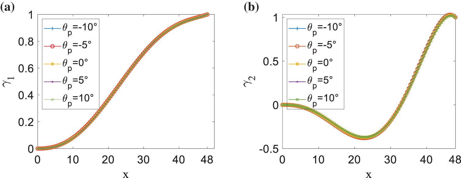
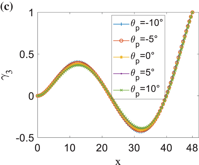
Figure 6: Influences of pitch angle θp on (a) first-order, (b) second-order, and (c) third-order modal functions, where Ω = 15 r/min
In this part, a harmonic pitch motion θp = Asin (ωpt + C) is adopted in analysis, where A, ωp, and C are the amplitude, angular frequency, and initial phase of the pitch angle with units deg, rad/s, and rad, respectively.
The natural frequency
Fig. 7 shows that when the values of pitch frequency ωp change, each natural frequency varies with pitch amplitude A dramatically. Fig. 8 presents the variation of frequency with pitch amplitude A when pitch phase C is taken as π/4 rad, π/2 rad, and π rad, respectively. It can be seen from Figs. 7 and 8 that the frequency changes with the pitch amplitude A: when the value of A is 110°, the frequency reaches the maximum, and then begins to change like an attenuation vibration; it reaches the second peak at A = 290°. It can also be seen that different values of pitch frequency ωp and pitch phase C do not affect the natural frequencies.

Figure 7: The influence of pitch amplitude A on frequency under different pitch frequency ωp: (a) first-order frequency; (b) second-order frequency; (c) third-order frequency, where C = 0 rad
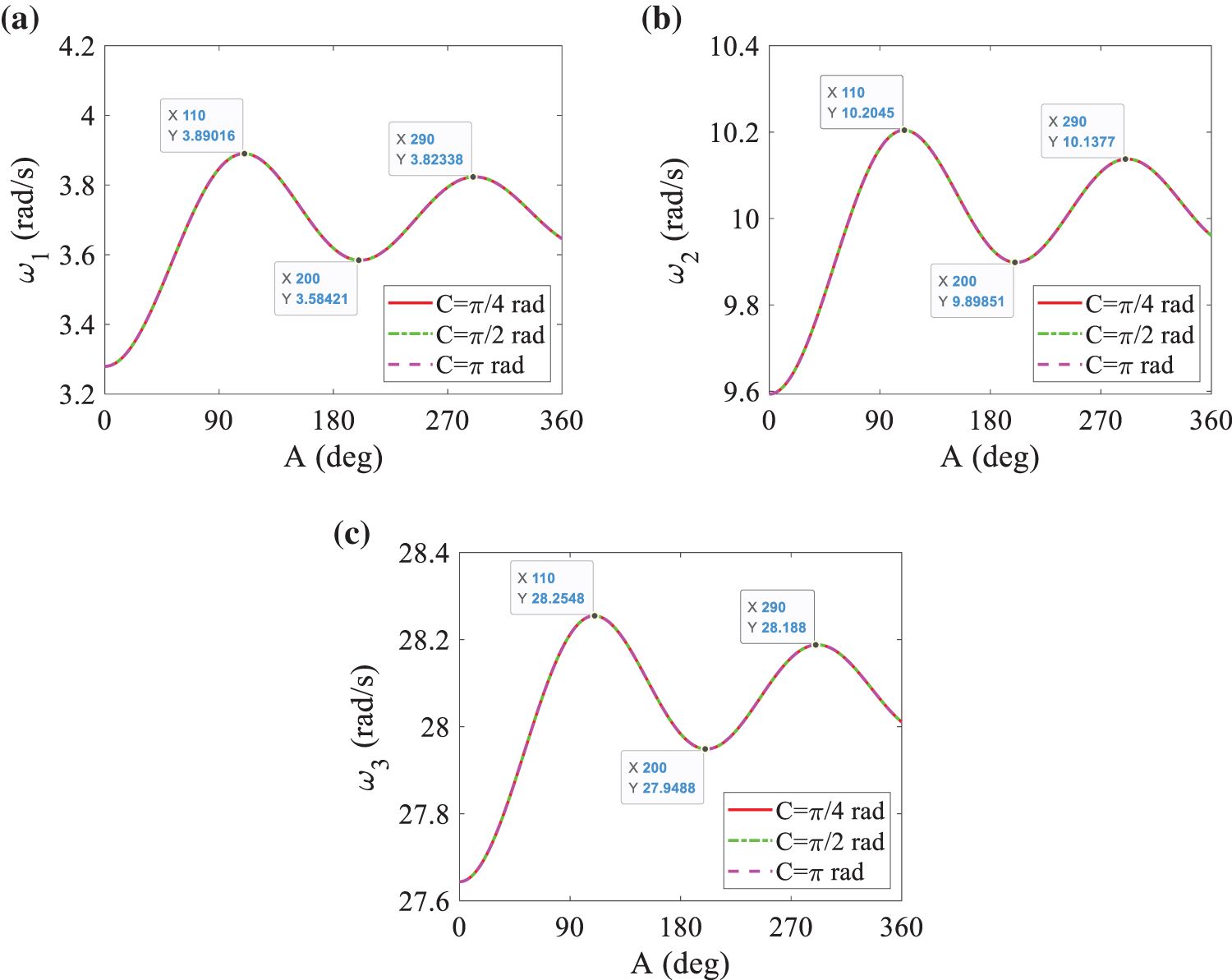
Figure 8: The influence of pitch amplitude A on frequency under different pitch phase C: (a) first-order frequency; (b) second-order frequency; (c) third-order frequency, where ωp = 1/2 rad/s
Fig. 9 shows that when the values of pitch amplitude A change, the frequency varies with the pitch frequency ωp. Fig. 10 reveals the variation of each frequency with the pitch frequency ωp when pitch phase C is taken as π/4 rad, π/2 rad, and π rad, respectively. Fig. 11 illustrates that when the values of pitch amplitude A are different, the frequency varies with the pitch phase C. Fig. 12 shows the variation of each frequency with the pitch phase C when pitch frequency ωp is taken as 1/2 rad/s, 3 rad/s, 5 rad/s, and π rad/s, respectively.

Figure 9: The influence of pitch frequency ωp on frequency under different pitch amplitude A: (a) first-order frequency; (b) second-order frequency; (c) third-order frequency, where C = 0 rad

Figure 10: The influence of pitch frequency ωp on frequency under different pitch phase C: (a) first-order frequency; (b) second-order frequency; (c) third-order frequency, where A = 5°

Figure 11: The influence of pitch phase C on frequency under different pitch amplitude A: (a) first-order frequency; (b) second-order frequency; (c) third-order frequency, where ωp = 1/2 rad/s
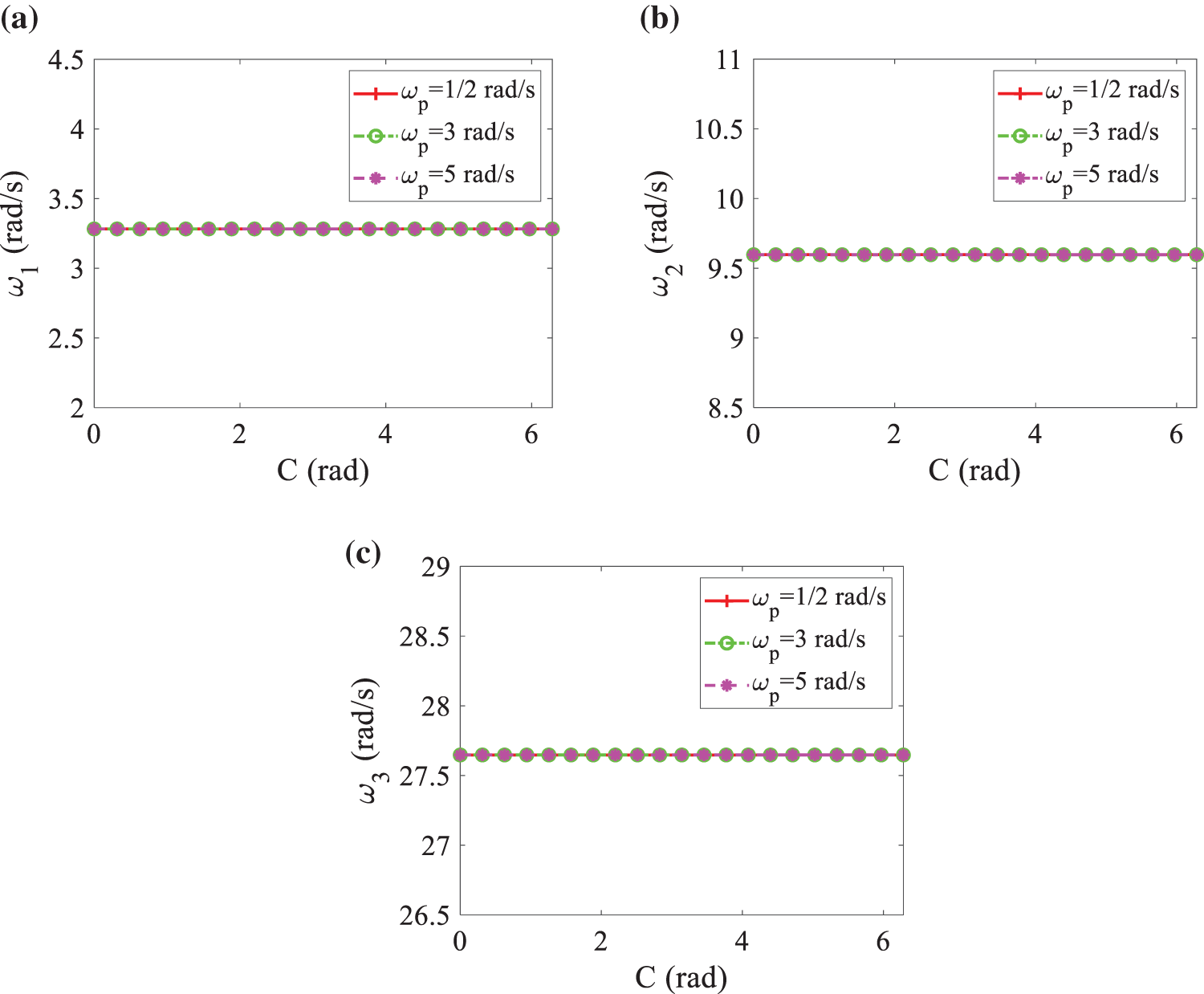
Figure 12: The influence of pitch phase C on frequency under different pitch frequency ωp: (a) first-order frequency; (b) second-order frequency; (c) third-order frequency, where A = 5°
It is found from Figs. 9 to 12 that the frequency does not change with the pitch frequency B and pitch phase C. However, the change in the value of the pitch amplitude A is different. It can be seen from Figs. 9 and 11 that when the value of the pitch amplitude A is 5°, 15°, 30°, and 60°, respectively, the frequency does not change with the pitch frequency ωp and pitch phase C, but its value increases, and Figs. 10 and 12 show that the values both of the pitch frequency ωp and pitch phase C do not change the values of frequencies. The results are consistent with the conclusions of Figs. 7 and 8.
In this paper, the influence of rigid pitch motion on flexible vibration characteristics of a wind turbine blade was studied. A nonlinear inherent coupled rigid-flexible dynamic model of a pitching blade is derived based on the generalized Hamiltonian principle. The combination of the assumed modes method and the multi-scales methods was proposed to deal with the linear modal problem. Natural characteristics of the blade with a harmonic pitch motion were analyzed. Effects of pitch motion on natural frequencies and mode shapes were analyzed. The following conclusions were obtained: (1) static pitch angle has little influence on the first three mode shapes for fixed rotating speed; (2) the amplitude of dynamic pitch motion influences the first three natural frequencies dramatically, while the influence of pitch frequency and pitch phase on natural frequencies is tiny; (3) the influence of dynamic pitch angle on vibration characteristics of the blade is very different from that of static pitch angle, so the conclusions for static pitch angle cannot be used to a dynamically pitching blade directly when vibration characteristics problem is considered; (4) natural frequencies increase with increasing rotating speed due to the centrifugal hardening effect.
Acknowledgement: None.
Funding Statement: This work has been supported by the University Outstanding Youth Researcher Support Program of the Education Department of Anhui Province, the National Natural Science Foundation of China (Grant Nos. 11902002 and 51705002), the Sichuan Provincial Natural Science Foundation (Grant No. 2022NSFSC0275), the Science and Technology Research Project of Chongqing Municipal Education Commission (Grant No. KJQN201901146) and the Special Key Project of Technological Innovation and Application Development in Chongqing (Grant No. cstc2020jscx-dxwtBX0048).
Author Contributions: The authors confirm contribution to the paper as follows: study conception and design: Zhan Wang, Liang Li; data collection: Zhan Wang, Long Wang; analysis and interpretation of results: Zhan Wang, Liang Li, Long Wang, Weidong Zhu, Yinghui Li, Echuan Yang; draft manuscript preparation: Zhan Wang, Liang Li, Weidong Zhu, Yinghui Li, Echuan Yang. All authors reviewed the results and approved the final version of the manuscript.
Availability of Data and Materials: The datasets used or analyzed during the current study are available from the corresponding author upon reasonable request.
Ethics Approval: Not applicable.
Conflicts of Interest: The authors declare that they have no conflicts of interest to report regarding the present study.
References
1. I. Chopra and J. Dugundji, “Non-linear dynamic response of a wind turbine blade,” J. Sound Vib., vol. 63, no. 2, pp. 265–286, Mar. 1979. doi: 10.1016/0022-460X(79)90883-6. [Google Scholar] [CrossRef]
2. J. W. Larsen and S. R. K. Nielsen, “Non-linear dynamics of wind turbine wings,” Int. J. Nonlin. Mech., vol. 41, no. 5, pp. 629–643, Jun. 2006. doi: 10.1016/j.ijnonlinmec.2006.01.003. [Google Scholar] [CrossRef]
3. J. W. Larsen and S. R. K. Nielsen, “Nonlinear parametric instability of wind turbine wings,” J. Sound Vib., vol. 299, no. 1–2, pp. 64–82, Jan. 2007. doi: 10.1016/j.jsv.2006.06.055. [Google Scholar] [CrossRef]
4. J. W. Larsen, R. Iwankiewicz, and S. R. K. Nielsen, “Nonlinear stochastic stability analysis of wind turbine wings by Monte Carlo simulations,” Probabilist Eng. Mech., vol. 22, no. 2, pp. 181–193, Apr. 2007. doi: 10.1016/j.probengmech.2006.11.002. [Google Scholar] [CrossRef]
5. S. P. Evans, D. R. Bradney, and P. D. Clausen, “Assessing the IEC simplified fatigue load equations for small wind turbine blades: How simple is too simple?” Renew Energy, vol. 127, no. 1, pp. 24–31, Nov. 2018. doi: 10.1016/j.renene.2018.04.041. [Google Scholar] [CrossRef]
6. Z. L. Mahri, M. S. Rouabah, and Z. Said, “Aeroelastic simulation of wind turbine blades,” Lect. Notes. Electr. Eng., vol. 11, pp. 313–323, May 2009. doi: 10.1007/978-0-387-76483-2. [Google Scholar] [CrossRef]
7. Z. L. Mahri and M. S. Rouabah, “Calculation of dynamic stresses using finite element method and prediction of fatigue failure for wind turbine rotor, WSEAS Trans,” Appl. Theor. Mech., vol. 3, no. 1, pp. 28–41, Jan. 2008. [Google Scholar]
8. T. R. Liu and Y. S. Ren, “Vibration and flutter of wind turbine blade modeled as anisotropic thin-walled closed-section beam,” Sci. China Technol. Sci., vol. 54, no. 3, pp. 715–722, Mar. 2011. doi: 10.1007/s11431-010-4230-y. [Google Scholar] [CrossRef]
9. T. R. Liu, Y. S. Ren, and X. H. Yang, “Nonlinear aeroelastic stability analysis of wind turbine blade with bending-bending-twist coupling,” J. Fluid Struct., vol. 42, no. 23, pp. 488–502, Oct. 2013. doi: 10.1016/j.jfluidstructs.2013.08.006. [Google Scholar] [CrossRef]
10. F. Georgiades, J. Latalski, and J. Warminski, “Equations of motion of rotating composite beam with a nonconstant rotation speed and an arbitrary preset angle,” Meccanica, vol. 49, no. 8, pp. 1833–1858, Aug. 2014. doi: 10.1007/s11012-014-9926-9. [Google Scholar] [CrossRef]
11. J. Warminski, L. Kloda, J. Latalski, A. Mitura, and M. Kowalczuk, “Nonlinear vibrations and time delay control of an extensible slowly rotating beam,” Nonlinear Dynam., vol. 103, no. 4, pp. 3255–3281, Mar. 2021. doi: 10.1007/s11071-020-06079-3. [Google Scholar] [CrossRef]
12. L. Li, Y. H. Li, Q. K. Liu, and H. W. Lv, “A mathematical model for horizontal axis wind turbine blades,” Appl. Math. Model., vol. 38, no. 11–12, pp. 2695–2715, Jun. 2014. doi: 10.1016/j.apm.2013.10.068. [Google Scholar] [CrossRef]
13. D. Y. Chen, C. J. Gu, P. Marzocca, J. D. Yang, and G. Pan, “Dynamic modeling of rotating blades system based on transfer matrix method of multibody system,” Appl. Math. Model., vol. 105, pp. 475–495, May 2022. doi: 10.1016/j.apm.2021.12.039. [Google Scholar] [CrossRef]
14. S. F. Fu et al., “Study on aerodynamic performance and wake characteristics of a floating offshore wind turbine under pitch motion,” Renew Energy, vol. 205, no. 1, pp. 317–325, Mar. 2023. doi: 10.1016/j.renene.2023.01.040. [Google Scholar] [CrossRef]
15. L. Cottura, R. Caradonna, R. Novo, A. Ghigo, G. Bracco and G. Mattiazzo, “Effect of pitching motion on production in a OFWT,” J. Ocean Eng. Mar. Ener., vol. 8, no. 3, pp. 319–330, Aug. 2022. doi: 10.1007/s40722-022-00227-0. [Google Scholar] [CrossRef]
16. W. Y. Shi, J. Jiang, K. Sun, and Q. Y. Ju, “Aerodynamic performance of semi-submersible floating wind turbine under pitch motion,” Sustain. Energy Technol. Assess., vol. 48, pp. 101556, Dec. 2021. doi: 10.1016/j.seta.2021.101556. [Google Scholar] [CrossRef]
17. X. Shen, X. C. Zhu, and Z. H. Du, “Load control and unsteady aerodynamics for floating wind turbines,” Proc Inst. Mech. Eng. Part A J. Power Eng., vol. 235, no. 6, pp. 1501–1526, Sep. 2021. doi: 10.1177/0957650921993255. [Google Scholar] [CrossRef]
18. Z. W. Li, B. R. Wen, X. J. Dong, X. H. Long, and Z. K. Peng, “Effect of blade pitch control on dynamic characteristics of a floating offshore wind turbine under platform pitching motion,” Ocean Eng., vol. 232, no. 1, pp. 109109, Jul. 2021. doi: 10.1016/j.oceaneng.2021.109109. [Google Scholar] [CrossRef]
19. H. Boudounit, M. Tarfaoui, D. Saifaoui, and S. El Garouge, “Structural design of offshore wind turbine blade spars,” Wind Eng., vol. 46, no. 2, pp. 343–360, Apr. 2022. doi: 10.1177/0309524X211027812. [Google Scholar] [CrossRef]
20. O. Lagdani, M. Tarfaoui, M. Nachtane, M. Trihi, and H. Laaouidi, “Modal analysis of an iced offshore composite wind turbine blade,” Wind Eng., vol. 46, no. 1, pp. 134–149, Feb. 2022. doi: 10.1177/0309524X211011685. [Google Scholar] [CrossRef]
21. B. S. Kallesøe, “Equations of motion for a rotor blade, including gravity, pitch action and rotor speed variations,” Wind Energy, vol. 10, no. 3, pp. 209–230, May/Jun. 2007. doi: 10.1002/we.217. [Google Scholar] [CrossRef]
22. S. Q. Wang, C. Y. Li, Y. Zhang, F. M. Jing, and L. F. Chen, “Influence of pitching motion on the hydrodynamic performance of a horizontal axis tidal turbine considering the surface wave,” Renew. Energy, vol. 189, no. 3, pp. 1020–1032, Apr. 2022. doi: 10.1016/j.renene.2022.03.062. [Google Scholar] [CrossRef]
23. T. R. Liu, C. L. Sun, K. Zhao, and A. L. Gong, “Amplitude control of stall-induced nonlinear aeroelastic system based on iterative learning control and unified pitch motion,” Energies, vol. 15, no. 3, pp. 787, Feb. 2022. doi: 10.3390/en15030787. [Google Scholar] [CrossRef]
24. Y. H. La, Y. S. Nam, and S. J. Hoon, “Individual pitch control of NREL 5MW wind turbine blade for load reduction,” Trans. Korean Soc. Mech. Eng. A, vol. 36, no. 11, pp. 1427–1432, Nov. 2012. doi: 10.3795/KSME-A.2012.36.11.1427. [Google Scholar] [CrossRef]
25. M. Moness and A. M. Moustafa, “Hybrid modelling and predictive control of utility-scale variable-speed variable-pitch wind turbines,” Trans Inst. Meas. Control., vol. 42, no. 9, pp. 1724–1739, Jun. 2020. doi: 10.1177/0142331219895117. [Google Scholar] [CrossRef]
26. M. Seyednia, M. Masdari, and S. Vakilipour, “The influence of oscillating trailing-edge flap on the dynamic stall control of a pitching wind turbine airfoil,” J. Braz. Soc. Mech. Sci. Eng., vol. 41, no. 4, pp. 1–15, Apr. 2019. doi: 10.1007/s40430-019-1693-z. [Google Scholar] [CrossRef]
27. M. S. Mahmoud and M. O. Oyedeji, “Continuous-time multi-model predictive control of variable-speed variable-pitch wind turbines,” Int. J. Syst. Sci., vol. 49, no. 11, pp. 2442–2453, Aug. 2018. doi: 10.1080/00207721.2018.1505001. [Google Scholar] [CrossRef]
28. C. Rainone, D. De Siero, L. Iuspa, A. Viviani, and G. Pezzella, “A numerical procedure for variable-pitch law formulation of vertical-axis wind turbines,” Energies, vol. 16, no. 1, pp. 536, Jan. 2023. doi: 10.3390/en16010536. [Google Scholar] [CrossRef]
29. A. Sagharichi, M. Zamani, and A. Ghasemi, “Effect of solidity on the performance of variable-pitch vertical axis wind turbine,” Energy, vol. 161, no. 5, pp. 753–775, Oct. 2018. doi: 10.1016/j.energy.2018.07.160. [Google Scholar] [CrossRef]
30. L. Li, I. Chopra, W. D. Zhu, and M. L. Yu, “Performance analysis and optimization of a vertical-axis wind turbine with a high tip speed ratio,” Energies, vol. 14, no. 4, pp. 996, Feb. 2021. doi: 10.3390/en14040996. [Google Scholar] [CrossRef]
31. C. Sendi, “Control of a variable blade pitch wind turbine subject to gust wind and actuators saturation,” Appl. Sci., vol. 11, no. 17, pp. 7865, Sep. 2021. doi: 10.3390/app11177865. [Google Scholar] [CrossRef]
32. J. C. Houbolt and G. W. Brooks, “Differential equations of motion for combined flapwise bending, chordwise bending, and torsion of twist nonuniform rotor blades,” in Technical Note 3905, Washington, DC, USA, NACA, 1957. [Google Scholar]
33. D. H. Hodges and E. H. Dowell, “Nonlinear equations of motion for the elastic bending and torsion of twisted nonuniform rotor blades,” in Technical Note D-7818, Washington, DC, USA, NASA, 1974. [Google Scholar]
34. L. Meirovitch, Computational Methods in Structural Dynamics (In Chinese). Beijing, China: National Defense Industry Press, 1987. [Google Scholar]
35. A. H. Nayfeh and D. T. Mook, Nonlinear Oscillations (In Chinese). Beijing, China: Higher Education Press, 1980. [Google Scholar]
36. W. Lacarbonara, H. Arvin, and F. Bakhtiari-Nejad, “A geometrically exact approach to the overall dynamics of elastic rotating blades—Part 1: Linear modal properties,” Nonlinear Dynam., vol. 70, no. 1, pp. 659–675, Oct. 2012. doi: 10.1007/s11071-012-0486-z. [Google Scholar] [CrossRef]
37. H. Arvin and F. Bakhtiari-Nejad, “Non-linear modal analysis of a rotating beam,” Int. J. Nonlin. Mech., vol. 46, no. 6, pp. 877–897, Jul. 2011. doi: 10.1016/j.ijnonlinmec.2011.03.017. [Google Scholar] [CrossRef]
38. H. Kim, H. Hee Yoo, and J. Chung, “Dynamic model for free vibration and response analysis of rotating beams,” J. Sound Vib., vol. 332, no. 22, pp. 5917–5928, Oct. 2013. doi: 10.1016/j.jsv.2013.06.004. [Google Scholar] [CrossRef]
Cite This Article
 Copyright © 2024 The Author(s). Published by Tech Science Press.
This work is licensed under a Creative Commons Attribution 4.0 International License , which permits unrestricted use, distribution, and reproduction in any medium, provided the original work is properly cited.
 Downloads
 Citation Tools