
 Submit a Paper
 Propose a Special lssue
 Open Access
ARTICLE

Test Research on the Knock of a Common-Rail Diesel Engine Fueled with Diesel-Methanol Dual-Fuel
1 State Grid Shaanxi Electric Power Research Institute, Xi’an, 710100, China
2 School of Energy and Electrical Engineering, Chang’an University, Xi’an, 710064, China
3 Shaanxi Key Laboratory of Development and Application of New Transportation Energy, Chang'an University, Xi’an, 710064, China
* Corresponding Author: Yangyang Li. Email:
Energy Engineering 2023, 120(5), 1081-1105. https://doi.org/10.32604/ee.2023.026000
Received 09 August 2022; Accepted 09 October 2022; Issue published 20 February 2023
 View Full Text
 Download PDF
Abstract
Experiments were conducted on a diesel-methanol dual-fuel (DMDF) engine modified by a six-cylinder, turbo-charged, inter-cooled diesel engine. According to the number of diesel injection, the experiments are divided to two parts: the single injection mode and double injection mode. The results show that, at the double injection mode, the maximum of pressure rise rate is small and the engine runs smoothly, however, knock still occurs when the co-combustion ratio (CCR) is big enough. Under knock status, the power density of the block vibration concentrating at some special frequencies rises dramatically, and the special frequency of single injection mode (about 4.1 kHz) is lower than that of double injection mode (7–9 kHz). The cylinder pressure oscillations of knock status are very different from the non-knock status. Under knock status, cylinder pressure oscillations become more concentrated and fiercer at some special frequencies, and the same as the block vibration. The special frequency of single injection mode (3–6 kHz) is lower than that of double injection mode (above 9 kHz).Keywords
Nomenclature
| DMDF | Diesel-methanol dual-fuel |
| BTDC | Before top dead center |
| CCR | Co-combustion ratio |
| PD | The power density of block vibration |
| MAPO | The maximum amplitude of pressure oscillation |
| θMAPO | The crank angel of the maximum of the pressure oscillation absolute value |
| SUMPO | The energy characteristic of pressure oscillation |
| PO | Pressure oscillation |
Diesel engines have been widely applied because of their high fuel efficiency and durability. However, because the air-fuel mixture and temperature in the combustion chamber are non-uniform, it is very difficult to reduce the smoke and NOx simultaneously which account for a majority of the emissions of diesel engines. Therefore, how to reduce NOx and smoke emissions simultaneously is a focus in the diesel engine research field. The exploration for fuel substitutes is a key method of solving this problem. Methanol has been regarded as one of the most promising fuel substitutes to rid China of the deficiency of fuel and prompt the adoption of clean coals because most of it is synthesized from coal in which China is abundant. Other methods to generate methanol include the chemical process of biomass using fermentation and syngas, implying that the access to methanol can be sustainable and environment-friendly [1,2]. Sayin applied methanol-diesel blends to the diesel engine and found that at high load (75%), between 1000 and 1800 rpm, smoke opacity, carbon monoxide and total hydrocarbon decreased [3]. They also found that operating parameters have obvious influence on the emissions: the increasing injection pressure and timing caused to decrease in the smoke opacity, CO, THC emissions [4]. The similar conclusions were verified with another test engine bench [5].
Diesel-methanol dual fuel (DMDF) is a method to apply methanol to diesel engines and has been widely investigated recently, which operates through injecting methanol at the intake tube under low pressure and diesel fuel in cylinder under high pressure. Wei et al. [6] conducted the DMDF mode on a turbo-charged diesel engine and tested the gaseous emission. It was found that DMDF mode could improve combustion stability and fuel economy at high MSR, and it can also reduce regulated emissions CO, THC. They also carried out experiments to reveal the reduction of PM emissions with oxidation catalyst (DOC) in a DMDF engine [7]. The results showed that at low and medium loads, there is a significant decrease in the dry-soot emission in DMDF mode before the DOC and the DOC could reduce the particulate mass and number concentrations significantly. The cylinder-to-cylinder variation of DMDF engine was also be studied [8]. The results showed that high methanol substitution percent (MSP) could increase the COV significantly, however, the increase of engine speed could decrease the cylinder-to-cylinder variation at high MSP. Yao et al. [9] conducted a comparative study on the effects of energy substitution ratio on the combustion characteristics and emission performance of a DMDF engine. The results showed that the higher the energy substitution ratio was, the lower the NOx emissions were. On the basis of the researches, the following conclusion could be drawn that DMDF mode could reduce diesel engine emissions without adverse impacts on the performance of diesel engines [10].
However, many studies also showed that, compared with diesel engines, both DMDF engines and other dual-fuel engines had a rougher operating performance, and, under some conditions, knocks would appear as the spark ignition engine. Depending on its frequency and intensity, knocking combustion can cause engine damage due to excessive thermal or mechanical stress on components. In SI engines, the unfavorable effects from knock are mainly breakage of piston rings, cylinder head erosion, increase air pollution and so on [11]. In the test DMDF engine, after knock-experiment, piston top land erosion and piston scraping appeared (Fig. 1).
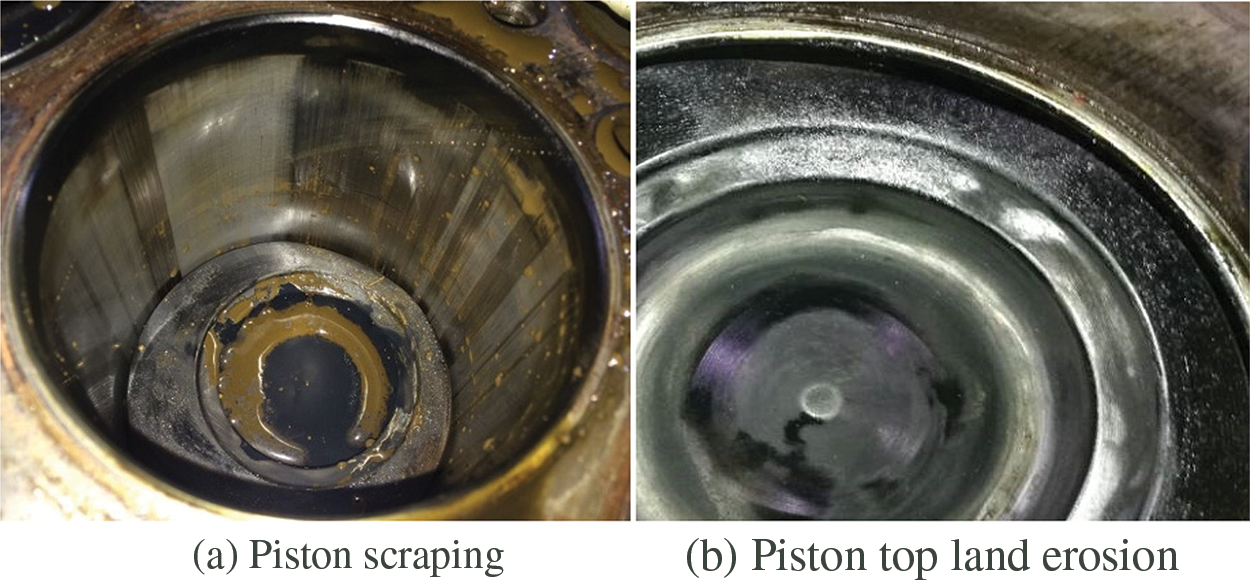
Figure 1: The damage of knock in the test DMDF engine
In some previous studies, characteristics such as maximum pressure rise rate and maximum peak-to-peak pressure [12,13] were adopted to judge the knock tendency, however, the indicators were usually used for the rough running diagnosis of diesel engine. The previous studies showed that in SI engines, cylinder pressure oscillation (PO) was of strong relativity to the knock intensity [14], and some PO characteristics could represent the knock intensity validly, such as MAPO [15,16] and IMPO [17]. In recent years, the knock combustion in dual fuel engine get more attention. Liu et al. built up a three-dimensional model to revealed the unique knock characteristics and mechanism of large-bore natural gas dual-fuel Marine engine [18]. Wang et al. [19] simulated knock combustion in a diesel-dimethyl ether (DME) engine to reveal the effects of premixed DME ratio, injection timing, and exhaust gas recirculation (EGR) rate on knock suppression. In the above two papers, MAPO was used as a significant indicator to diagnose the knock intensity. Huayu et al. modelled a large marine four-stroke dual-fuel engine and KI was applied to quantify the phenomenon of knock [20].
Above all, the previous studies of DMDF engines mainly focused on the combustion,performance and emissions. Some studies used several traditional parameters to investigate the rough running and other research used the PO characteristics. However, most of the researches focus on simulation research and few of them used methanol as the premix fuel, so there is still lack of experimental study concerning knocks of DMDF engines. In this study, the tested DMDF engine operated in the single and double-injection modes separately, and the FFT and Chebyshev filter were used to analyze the block vibration and the cylinder pressure data. The power density (PD) of block vibration, the maximum amplitude of pressure oscillation (MAPO), the phase characteristic of pressure oscillation (θMAPO) and the energy characteristic of pressure oscillation (SUMPO) were calculated to investigate the DMDF knock.
2 Experimental Setup and Method
2.1 The System of the Test Engine
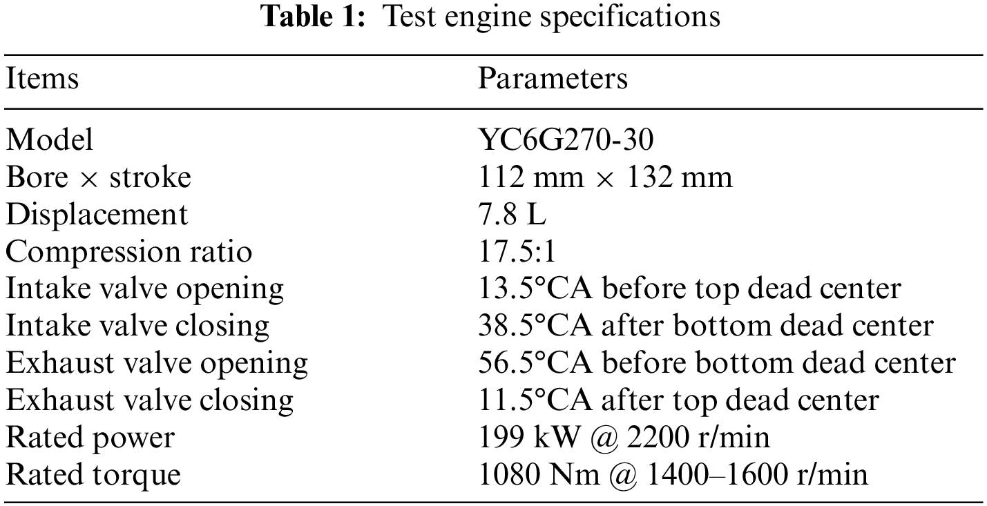
To investigate the knocks of DMDF engines, a common rail diesel engine was adopted which has an in-line six-cylinder and can be charged by a turbo, and cooled internally. Table 1 shows the characteristics of the test engine in this research.
This research utilized three methanol injectors and a methanol rail installed in the intake manifold’s head to inject methanol and blend it with fresh air. To achieve the homogeneous methanol-air mixture, methanol was injected with 0.4 MPa pressure. Diesel was injected into the cylinder using the BOSCH supply system and controlled by an added electronic control unit (ECU) in the diesel single injection mode. However, in double-injection mode, the diesel injection operation was under the control of the initial diesel ECU. Fig. 2 shows the schematic of the test engine.
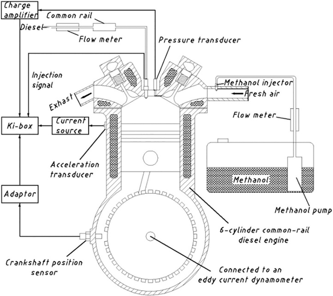
Figure 2: The schematic of the test engine
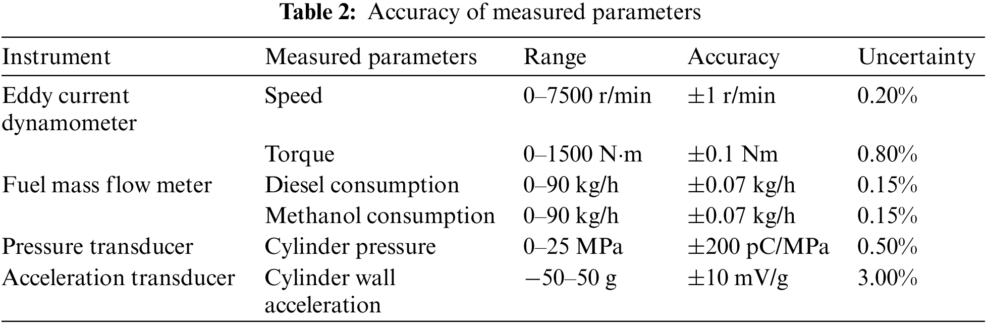
The speed and torque of the engine was automatically controlled by an eddy current dynamometer (CW260, CAMA). A piezo-electric pressure transducer (6052A, Kistler) was installed on the same horizontal plane with the first cylinder head so that its in-cylinder pressure can be measured. A charge amplifier (5019B, Kistler) was utilized prior to the transfer of the signal of pressure to the combustion analyzer (Kibox, Kistler) in order to guarantee the amplification of the signal. The test engine’s block vibration was measured through fixing an acceleration transducer (8702B50, Kistler) in the wall of the first cylinder. In addition, the signal of vibration was modified by a signal conditioner (YE3826A, Sinocera). Moreover, the crank angle’s position was measured using a crank angle adapter (2619, Kistler) that could send the crank angle’s signal with the 0.1° resolution. The consumptions of diesel fuel and methanol were measured separately using two different mass flow meters (Coriolis type) of EMERSON. During the process, the accuracy of test results was ensured through conducting the same tests for multiple times. Table 2 presents the measuring accuracies.
The data of the crank angle and cylinder pressure provided an ample basis for the calculation of the rate of heat release using a combustion analysis system (CDA2.55, Kistler). Prior to the heat release rate calculation, the impacts of cycle-to-cycle variations were offset through the collection and averaging of data of the cylinder pressure of 100 cycles. Next, a single-zone heat release model was utilized to measure the rate of heat release in accordance with the first law of thermodynamics on the basis of three hypotheses. First, blending distribution and temperature of fuel and air are homogeneous in cylinder. Secondly, working medium in cylinder is believed as ideal gas. Third, any possibility of conditions such as air-tight failure or leakage in the cylinder is excluded. This model included the heat-transfer effect into the analysis when measuring the rate of heat release, and adopted the Woschni’s expression to calculate the heat-transfer coefficient, which is considered as a key parameter in the research.
Co-combustion ratio (CCR) is defined as the percentage of methanol energy to the dual-fuel energy, given by
where,
Accelerometers have been widely used in the SI engine electronic-controlled system to detect knock because this technique is cheap, simple and durable [21,22]. Accelerometers are usually placed on cylinder blocks to collect the block vibration signals in time function, and these signals are transformed to frequency function by using Fourier based methods to monitor the power spectrum of the resonant frequency. In this paper, the vibration data were converted by fast Fourier transform (FFT), and then the power density (PD) was calculated from the FFT data to show the dedicated frequencies which energy is concentrated around. The example vibration data and their PD are shown in Fig. 3. The Periodogram method was applied to estimate the power spectrum. The power density (PD) is expressed as follows:
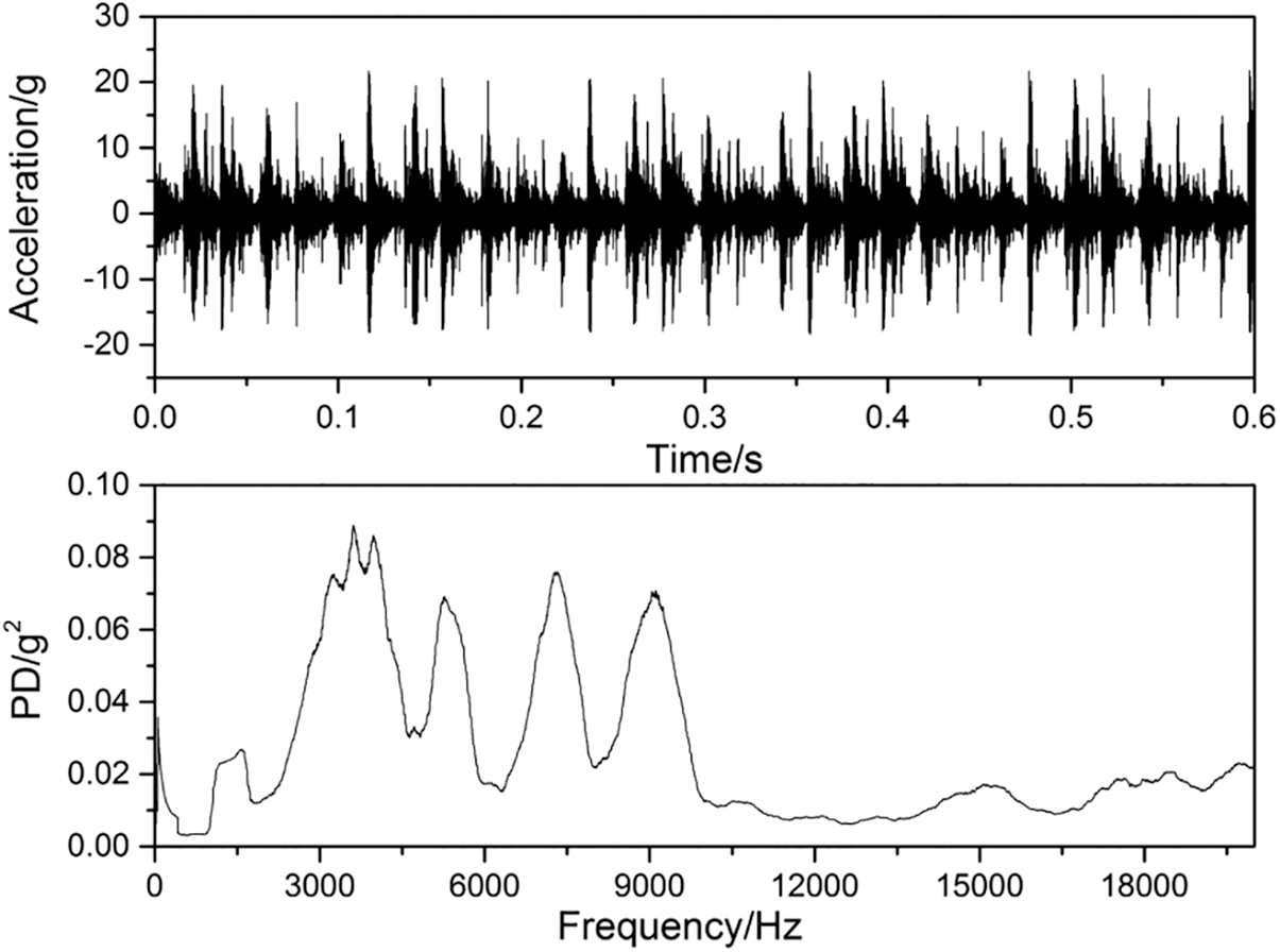
Figure 3: The vibration signal and its power density
where, R and I are the real and imaginary parts of the vibration data after FFT, n is the length of the input sequence.
2.2.4 Cylinder Pressure Oscillation
In this paper, different cut-off frequencies of high-pass Chebyshev filters (1, 3, 6 and 9 kHz) were used to process the cylinder pressure oscillations to derive the pressure oscillation. The cylinder pressure and its oscillation after high-pass Chebyshev filter are shown in Fig. 4. The characteristics used to investigate the DMDF engines knock are MAPO, θMAPO and SUMPO.
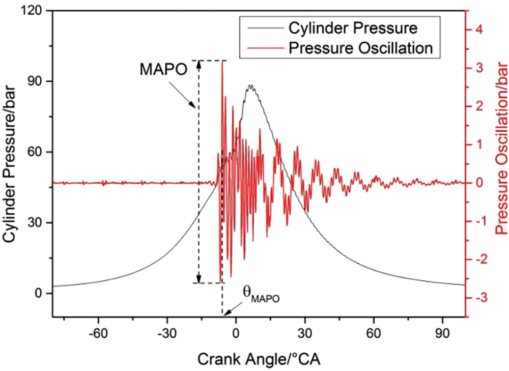
Figure 4: The cylinder pressure and its oscillation
The maximum amplitude of pressure oscillation (MAPO) is expressed as follows:
where, POmax is the maximum of pressure oscillation and its value is positive, POmin is the minimum of pressure oscillation and its value is negative.
θMAPO is the crank angel of the maximum of the pressure oscillation absolute value (|PO|) and it can show the phase characteristic of pressure oscillation.
From the cylinder pressure oscillation shapes, it could be seen that the cylinder pressure oscillation appears suddenly without gradual increase period, and then it disappears gradually. Most of the oscillations are distributed at the early period and around the maximum oscillation, so MAPO could represent the oscillation intensity of the cylinder pressure to some extent. However, the durations of pressure oscillation are very different, and the intensity of pressure the oscillation with a small MAPO but long duration is likely to be fiercer than the one with big MAPO. In this paper, a parameter named SUMPO is calculated by using both amplitude of pressure oscillation and its duration to describe the pressure oscillation energy of one cycle, and is expressed as follows:
2.3 Test Method and Conditions
Experiments were conducted under different speeds (1000 and 1400 r/min which is the engine maximum torque speed), load ratios (50% and 70%) and diesel injection modes (single injection and double injection). Engine test conditions are shown in Table 3. The injection signals of different injection modes are shown in Fig. 5.
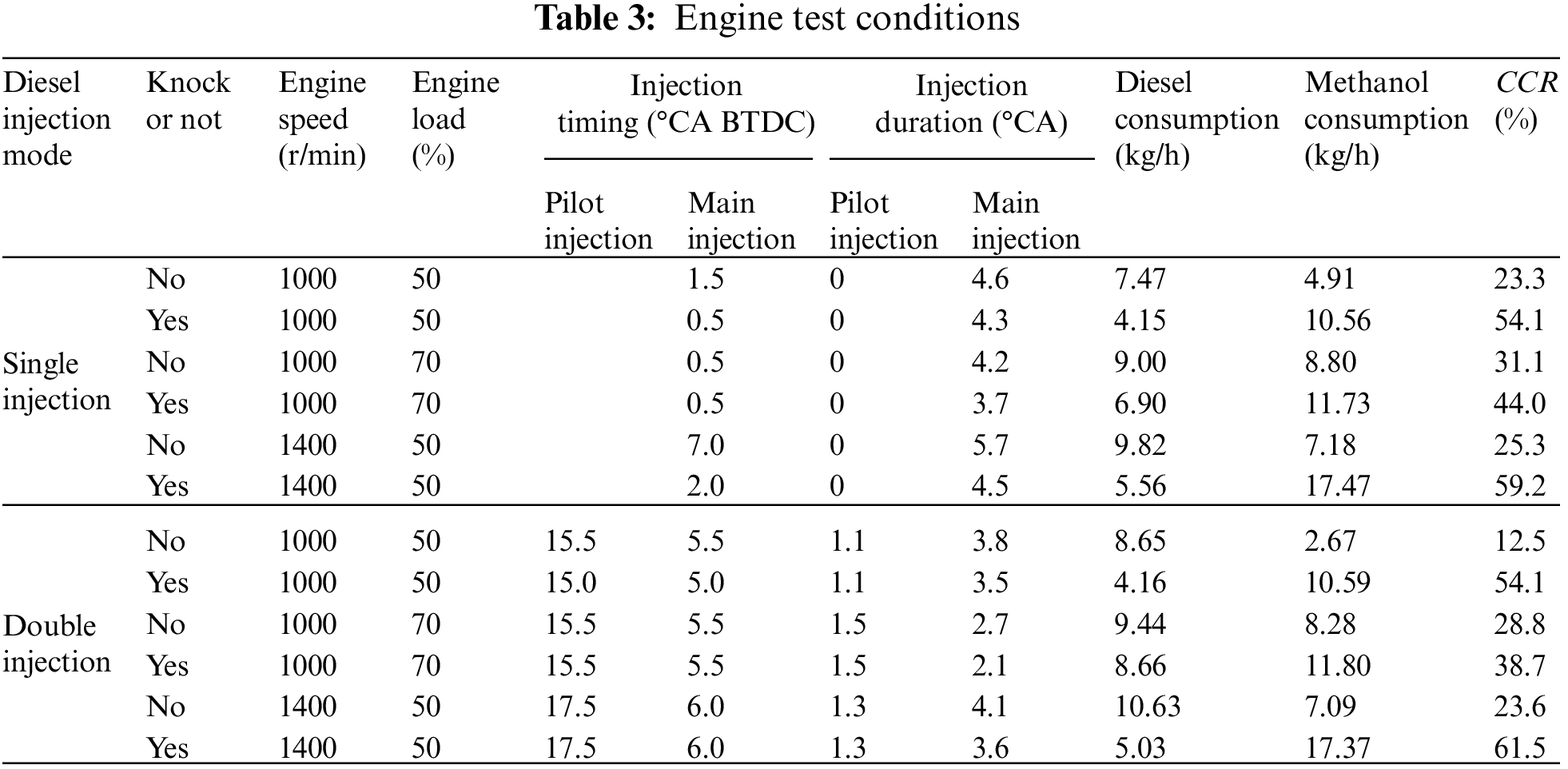
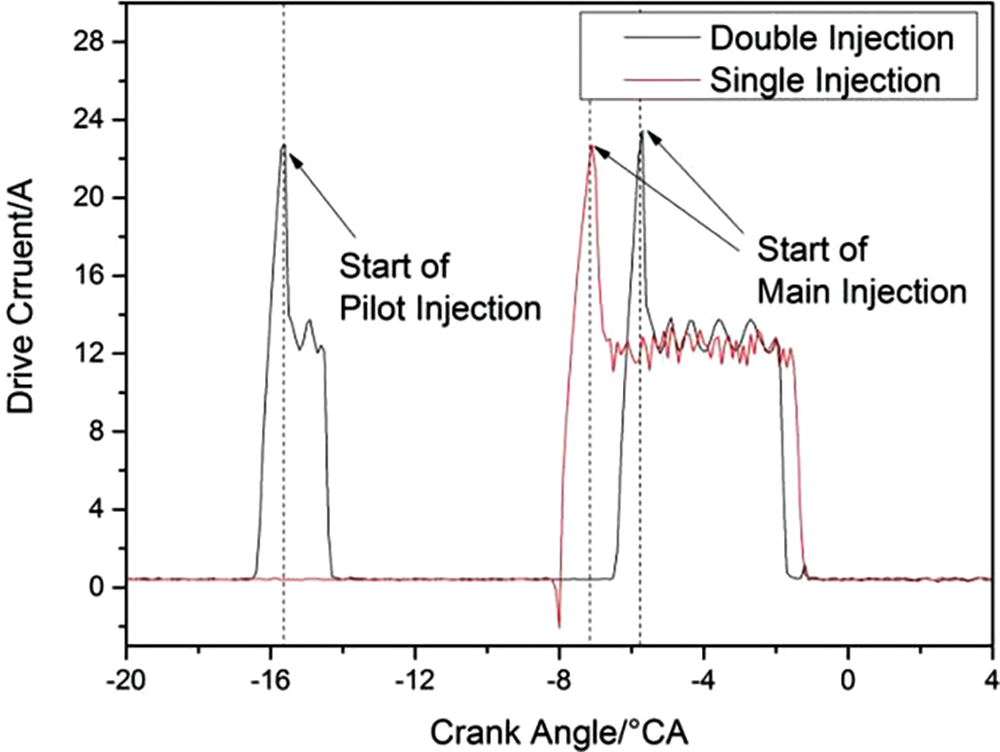
Figure 5: Two types of diesel injection
At the single injection mode, both diesel and methanol injections were controlled by the added ECU. At the DMDF testing procedure, the diesel injection parameters should be set firstly. For example, when the test condition aimed to be 1400 r/min, 50% load (540 N⋅m), 25%CCR, the diesel injection timing was set to a classical value at first, such as 10°CA BTDC, and injection duration should be set to a proper value to make sure the engine torque get to 405 N⋅m. Then, the methanol injection duration was increased by the added ECU to make the engine torque get to 540 N⋅m. However, the premix-methanol would increase the cylinder pressure rise rate obviously and cause fierce rough running. Sometimes the maximum cylinder pressure rise rate could get to 3 MPa/°CA or even bigger before knock occurred and the rough operation may destroy the test engine. In many previous studies, the expected maximum cylinder pressure rise rate was less than 1 MPa/°CA. However, in this study, at some conditions, the injection timing was even delayed to 0°CA, and the maximum cylinder pressure rise rate was still larger than 1 MPa/°CA. At the same time, excessively delayed injection would reduce the engine efficiency and even cause misfire, so the expected maximum cylinder pressure rise rate was set to less than 1.8 MPa/°CA in this study. Then, the diesel injection timing should be adjusted to decrease the maximum cylinder pressure rise rate. The adjustment of injection timing may cause the decrease of engine torque, and the injection duration of methanol should be increase to make sure the engine load stable. When the engine load got to 540 N⋅m and operated stably, the consumptions of diesel and methanol were tested simultaneously to confirm the CCR.
At double injection mode, only the methanol injection was controlled by the added ECU, and the diesel injection was controlled by the original BOSCH ECU, because the added ECU designed originally cannot output double injection signals. By changing the accelerator pedal position signal, the diesel injection quantity and timing could be changed, it means that the double injection parameters were selected from the MAP in the BOSCH ECU automatically. We could not change them as precise as single injection mode. At double injection mode, the maximum cylinder pressure rise rate is very low even at knock, so the main injection timing was not need to adjust. The testing procedure of double injection mode is similar to single injection mode: the diesel injection parameters were determined firstly and methanol injection parameter was set secondly.
The vibration power densities (PDs) of single injection mode at different operation conditions are shown in Fig. 6. Most of the PDs appear below 20 kHz, and concentrate around 4, 7 and 9 kHz. When knock occurs, the PDs around 4 kHz rise sharply. With the increase of speed (1000 to 1400 r/min), the maximum PD increases (0.25 to 0.30, as shown in Figs. 6a and 6c), however, the maximum PD keeps stable with the increase of load (50% load to 70% load, as shown in Figs. 6a and 6b). It is possible that with the increase of load, the temperature in cylinder increases, however, under knock status, the CCR decrease from 54.1% to 44.0% and the methanol-air mixture excess air ratio increases from 3.40 to 4.57. There exists a trade-off between concentration and temperature of the reactant under knock status, and the strength of vibration caused by knock remains stable.
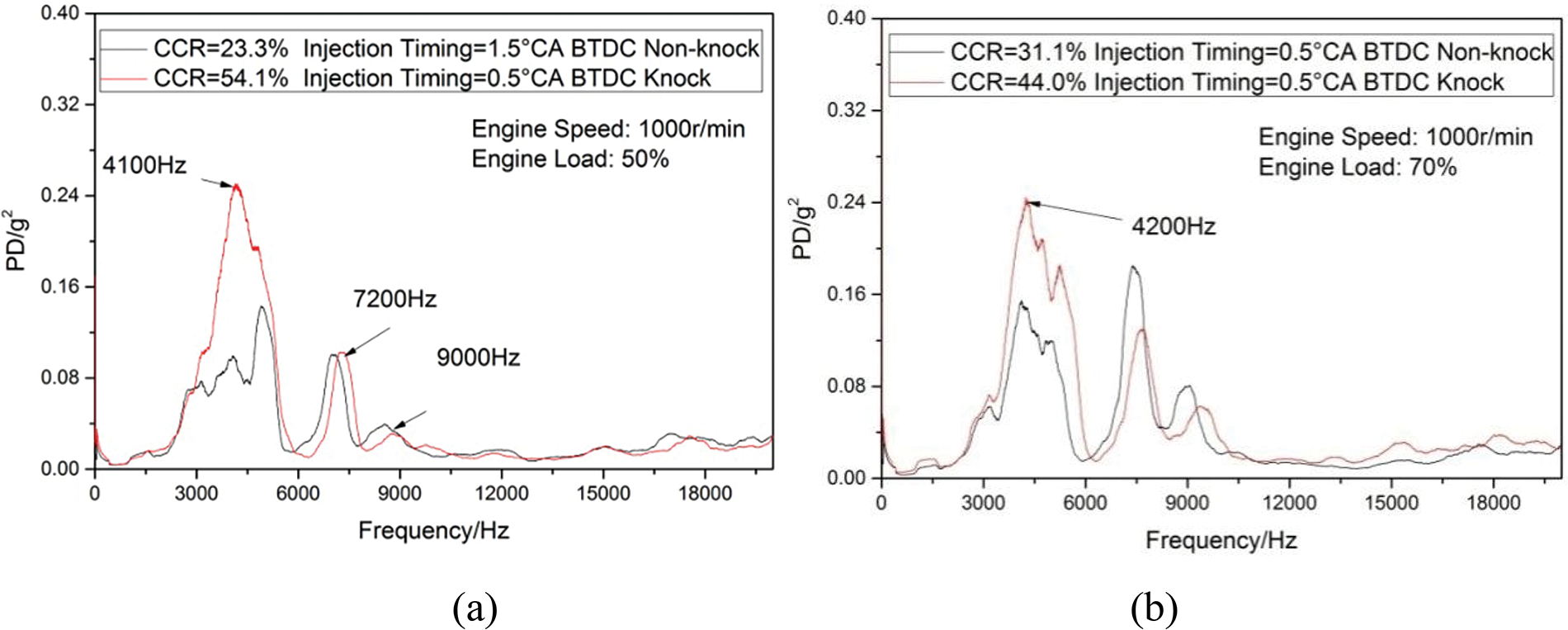
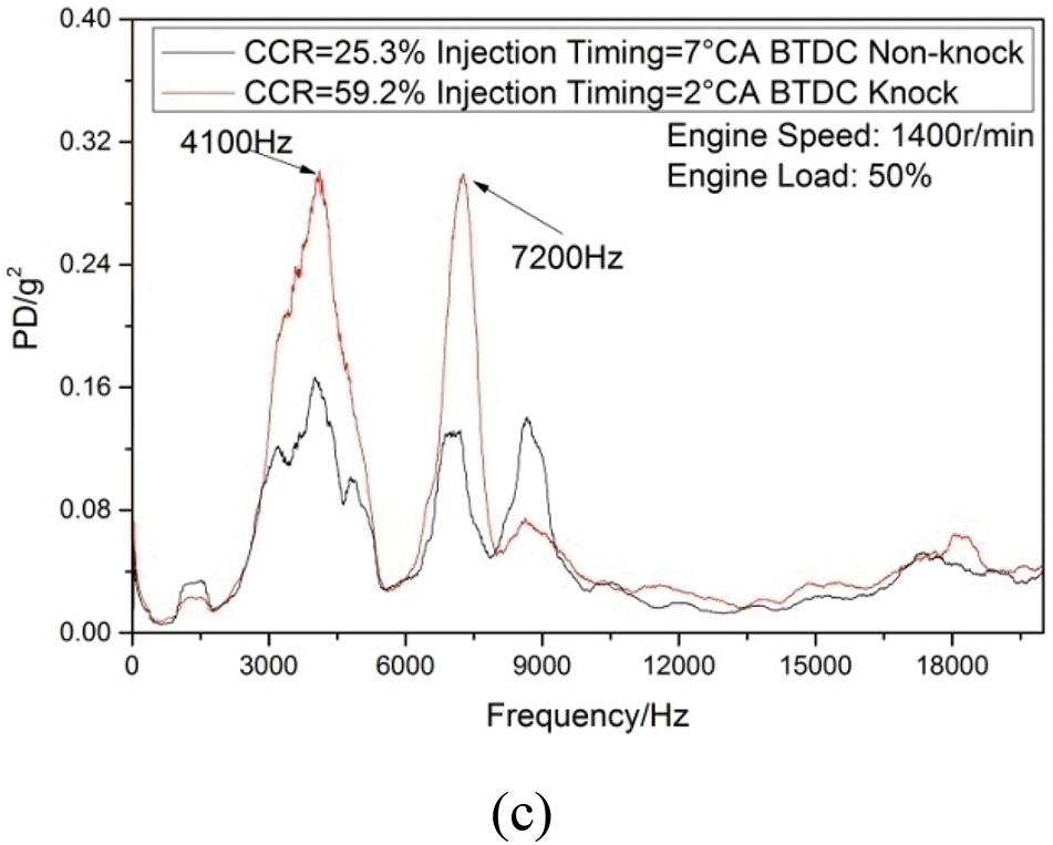
Figure 6: Bration power density of single injection mode
However, at 1400 r/min, 50% load, PD is obviously higher than 1000 r/min, 50% and 70% load. The reason is that 1400 r/min is the max-toque speed, 50% load means higher BMEP and higher incylinder temperature than the same load rate at 1000 r/min. In addition, the knock-CCR at 1400 r/min, 50% load is very large (59.2%), which means the excess air ratio of methanol-air is the smallest (3.19) in the 3 test conditions. Richer methanol-air’s leads to fiercer auto-ignition and increases knock intensity.
It is believed that the in-cylinder pressure oscillations at knock affect the block vibration greatly. As shown in Fig. 7, the pressure oscillation becomes fiercer at knock. At the same time, the pressure rise rate increases slightly and the maximum is about 0.8 MPa/°CA, so high pressure rise rate is not the cause of knock and the maximum of pressure rise rate is not suitable for valuing knock intensity.
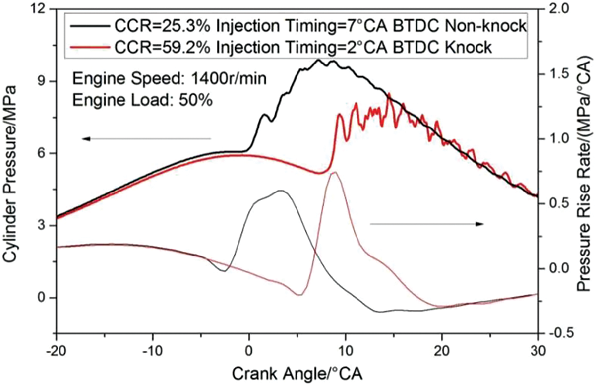
Figure 7: Cylinder pressure and the pressure rise rate of single injection mode
As shown in Fig. 8, the cylinder pressure of one cycle is processed by using 1, 3, 6 and 9 kHz high-pass filters. The pressure oscillation of knock status, processed by 3 kHz high-pass filter, is obviously fiercer than that of non-knock status. However, processed by other filter, the pressure oscillation is weaker. The conclusion is that the pressure oscillation between 3 and 6 kHz has a close relationship with knock.

Figure 8: Cylinder pressure oscillations of single injection mode
To investigate the effects of pressure oscillation on knock further, the pressure signals of 100 cycles are collected and calculated some special characteristics of pressure oscillation. Fig. 9 shows MAPO and its mean of 100 cycles (meanMAPO). It is observed that MAPO decreases with the frequency increasing. MAPO of knock gets closer to the non-knock status with the frequency increases, and at some conditions, MAPO of knock could become smaller than that of non-knock at 6 and 9 kHz.
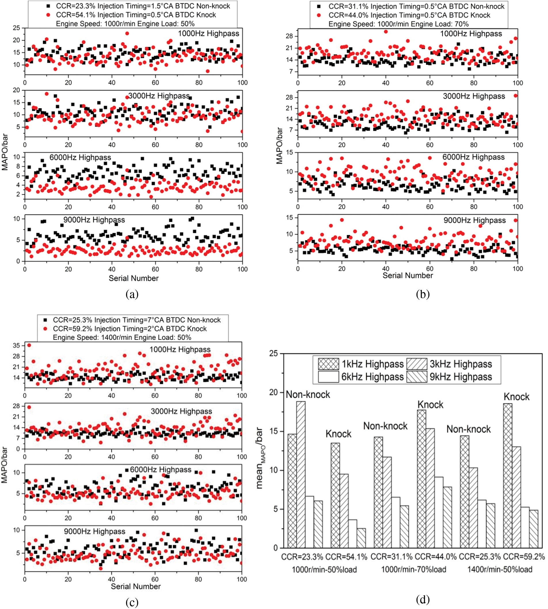
Figure 9: The MAPOs of single injection mode
It also can be seen that, MAPO at knock becomes smaller than non-knock. That is because according to Draper’s acoustic model [23], the knock combustion pressure oscillation at single injection mode in this engine is probably the first propagation mode for its 1~3 kHz response frequency. At this propagation mode, knock pressure oscillation propagates from one side to another side in cylinder. The propagations delay the high frequency pressure oscillations and the impact on the pressure wave from fire-core reduce the power of the high frequency pressure oscillations.
Fig. 10 shows θMAPO and its mean of 100 cycles (meanθ). It is observed that compared with θMAPO at non-knock, θMAPO at knock does not show regular changes. However, θMAPOs of different frequencies at knock status are more centralized than that of non-knock, which means that the pressure oscillation is more centralized under knock status and it would intensify the engine block vibration.
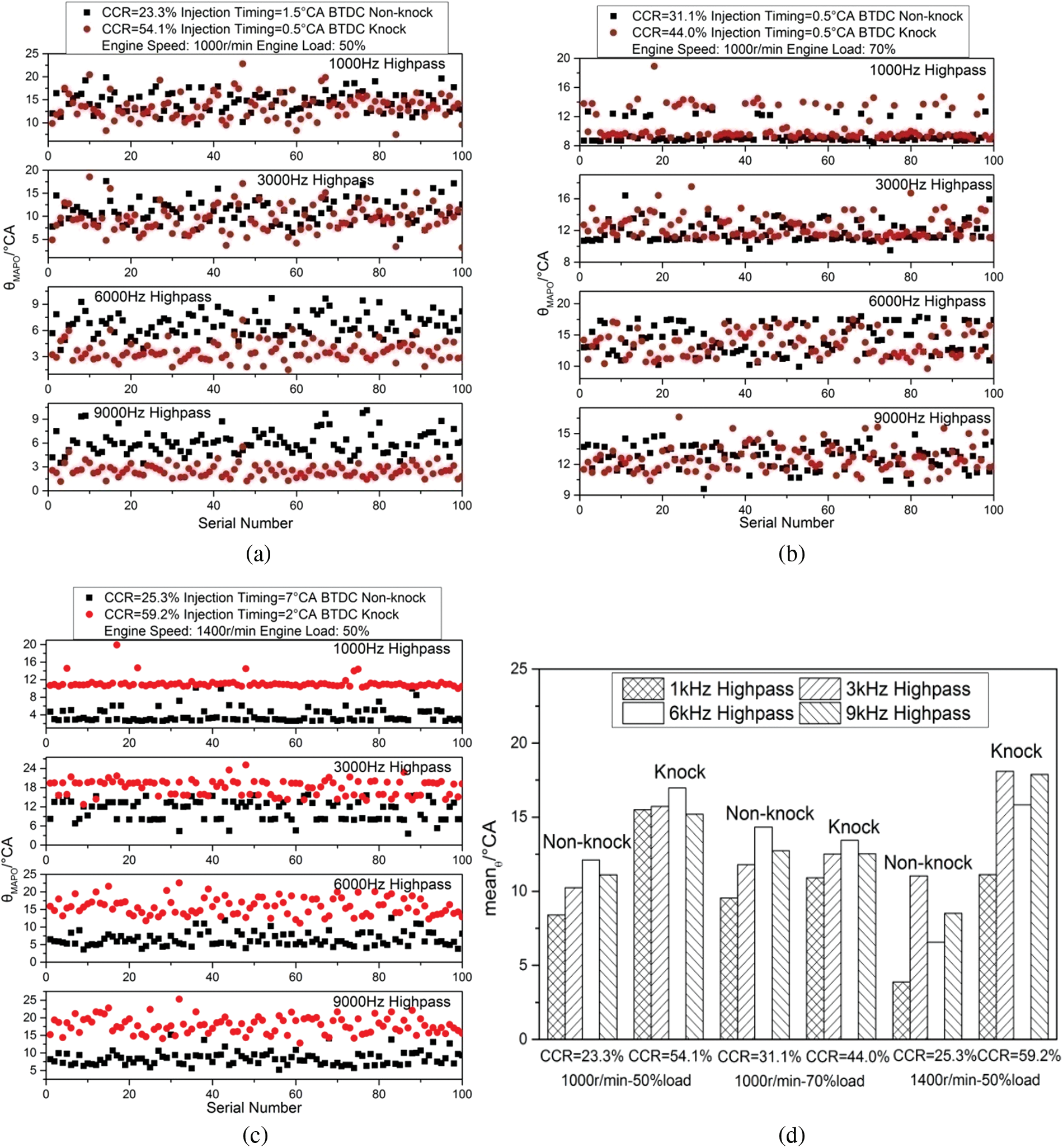
Figure 10: The θMAPOs of single injection mode
Fig. 11 shows SUMPO and its mean of 100 cycles (meanSUM). It is observed that compared with SUMPO under non-knock status, SUMPO under knock status shows an obvious increase at low frequencies (1 and 3 kHz), which corresponds to the block vibration results.
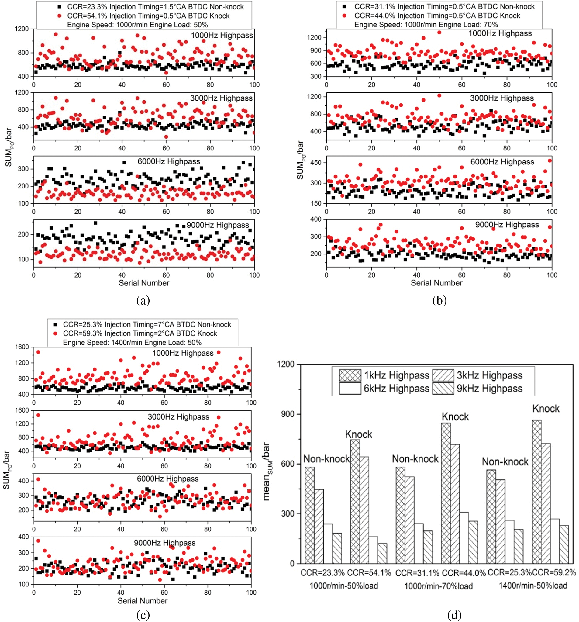
Figure 11: He SUMPOs of single injection mode
Fig. 12 shows the heat release rate at different conditions. In Fig. 12, the red and black arrows point to the meanθs of knock and non-knock, respectively. It is observed that the heat release rate curve of knock is obvious different from non-knock. Compared with non-knock, when knock occurs, the peak heat release rate increases, the heat release is concentrated and delayed, the pressure oscillations concentrate on the late combustion phase, and the heat release rate curve fluctuates after the pressure oscillations.
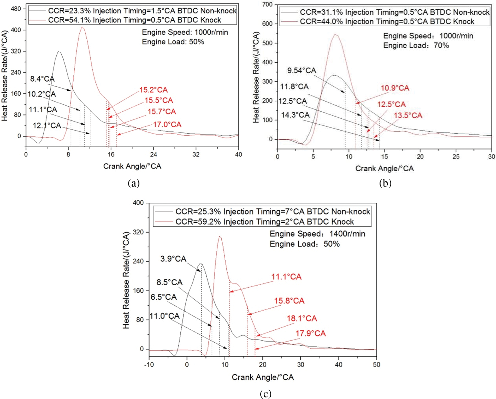
Figure 12: The heat release rates of single injection mode
From the data above, several conclusions could be deduced. First, the knock makes the cylinder pressure oscillation at special frequency bands fiercer and more concentrated, which increases the engine block vibration and makes the ringing ‘knock noise’ to be heard by the testers. Second, it is very likely that the combustion period which leads to knock after the premix combustion. The methanol unburned at premix combustion period auto-ignites because of the high temperature, then the auto-ignition flame, around the diesel injection area, propagates to the center of the cylinder and impacts against the diffusion combustion flame. The flame impact leads to fierce pressure oscillations and lasts for a long time, which makes the combustion unstable at the next combustion phase.
The engine block vibration power densities (PDs) of double injection mode are shown in Fig. 13. It can be seen that most of the vibration PDs of double injection mode appear below 20 kHz and concentrate around 4, 7 and 9 kHz, which is the same as single injection mode. However, the PD of double injection mode rise sharply around 7 and 9 kHz at knock, which is higher than that of single injection mode (4 kHz). As shown in Fig. 13, with the increase of speed (1000 to 1400 r/min), the maximum PD increases (0.12 to 0.20), at the meantime, the maximum PD keeps stable with the increase of load (50% load to 70% load), which could be explained as the single injection mode does. It could also be found that the vibration PDs of double injection mode are lower than these of single injection mode. This is because the pressure rise rate of double injection mode is lower, and the engine runs smoother than single injection mode.

Figure 13: Vibration power density of double injection mode
Fig. 14 shows the cylinder pressures and the pressure rise rates of double injection mode at knock and non-knock. It seems that when knock occurs, the pressure signal becomes smoother than single injection mode at non-knock, and other researchers also found similar phenomenon [24,25]. It was found that pressure oscillations always appeared with high pressure rise rate, and at single injection mode, high pressure rise rate is obviously higher than double injection mode, even knock appears at double injection mode.
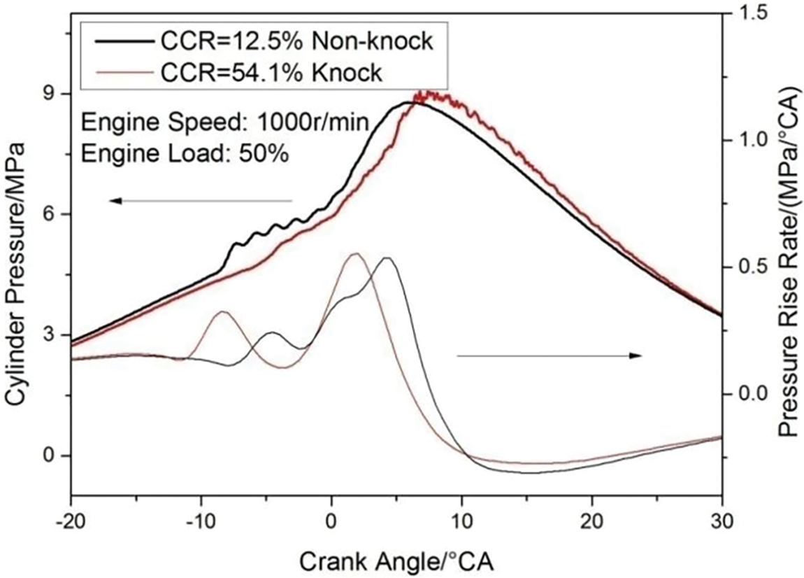
Figure 14: Cylinder pressure and the pressure rise rate of double injection mode
However, as shown in Fig. 15, after filtered by different frequencies high-pass filters, the cylinder PO of knock (over 9 kHz) is much fiercer than non-knock. At the same time, the maximum of pressure rise rate is about 0.6 MPa/°CA, which means the engine operation is smooth at knock. It could be confirmed that rough running and knock of DMDF engines are different, and the maximum of pressure rise rate which is used to measure the rough running is not suitable for knock.
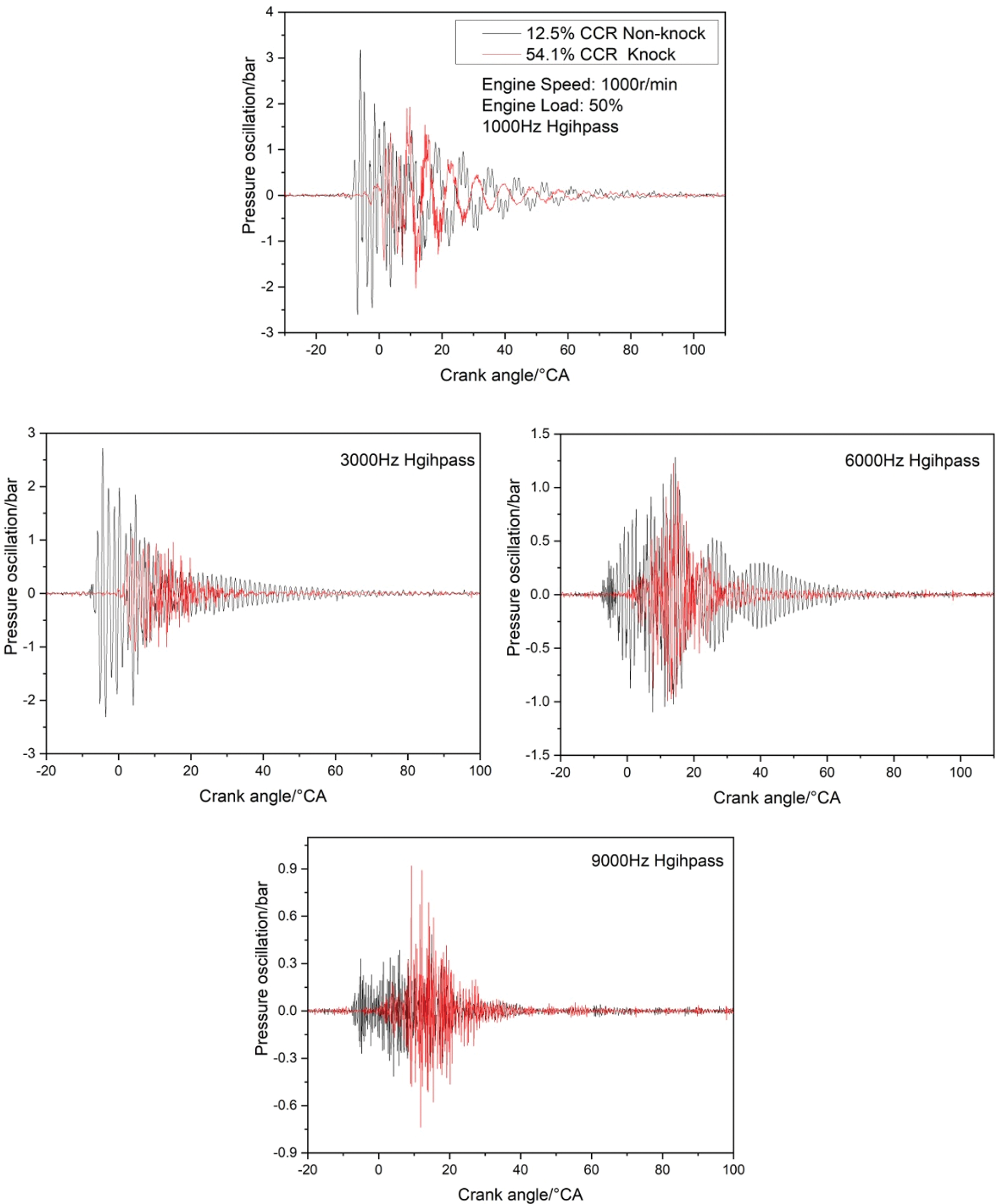
Figure 15: Cylinder pressure oscillations of double injection mode
Some characteristics (MAPO, meanMAPO, θMAPO, meanθ, SUMPO and meanSUM) of pressure oscillation of 100 cycles are shown in Figs. 16–18. The same as single injection mode, MAPO and SUMPO decrease with the frequency increasing both knock and non-knock, and θMAPOs of different frequencies at knock become more centralized. However, the characteristic pressure oscillation frequency of knock is different, which is above 6 kHz and higher than that of single injection mode.
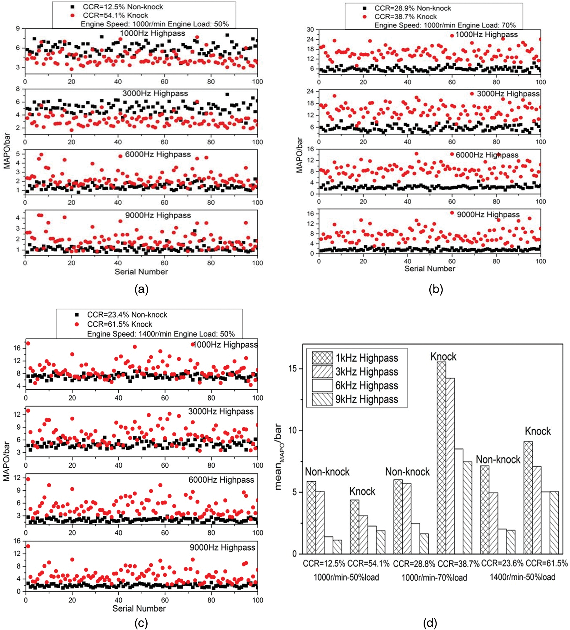
Figure 16: The MAPOs of double injection mode
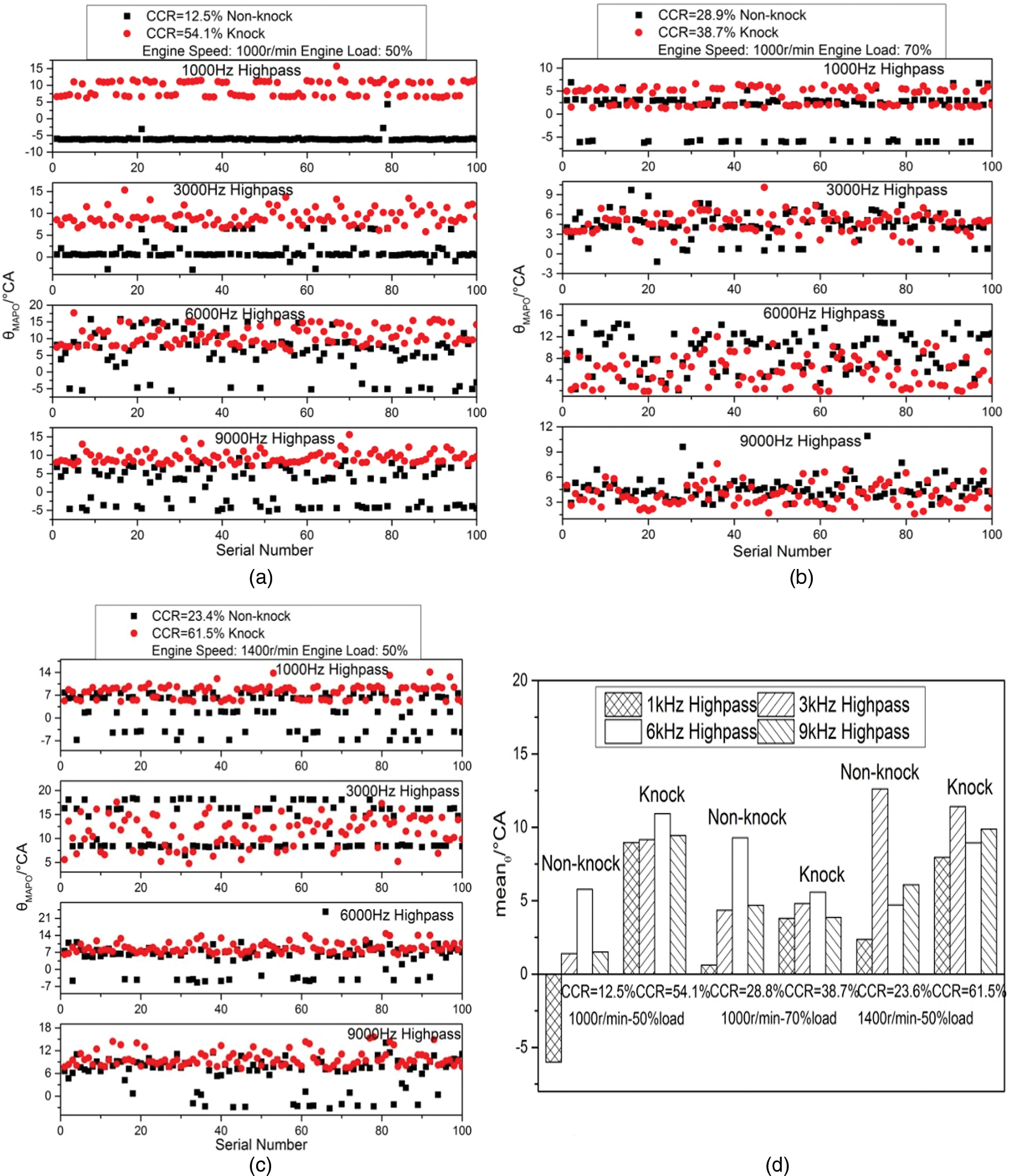
Figure 17: The θMAPOs of double injection mode
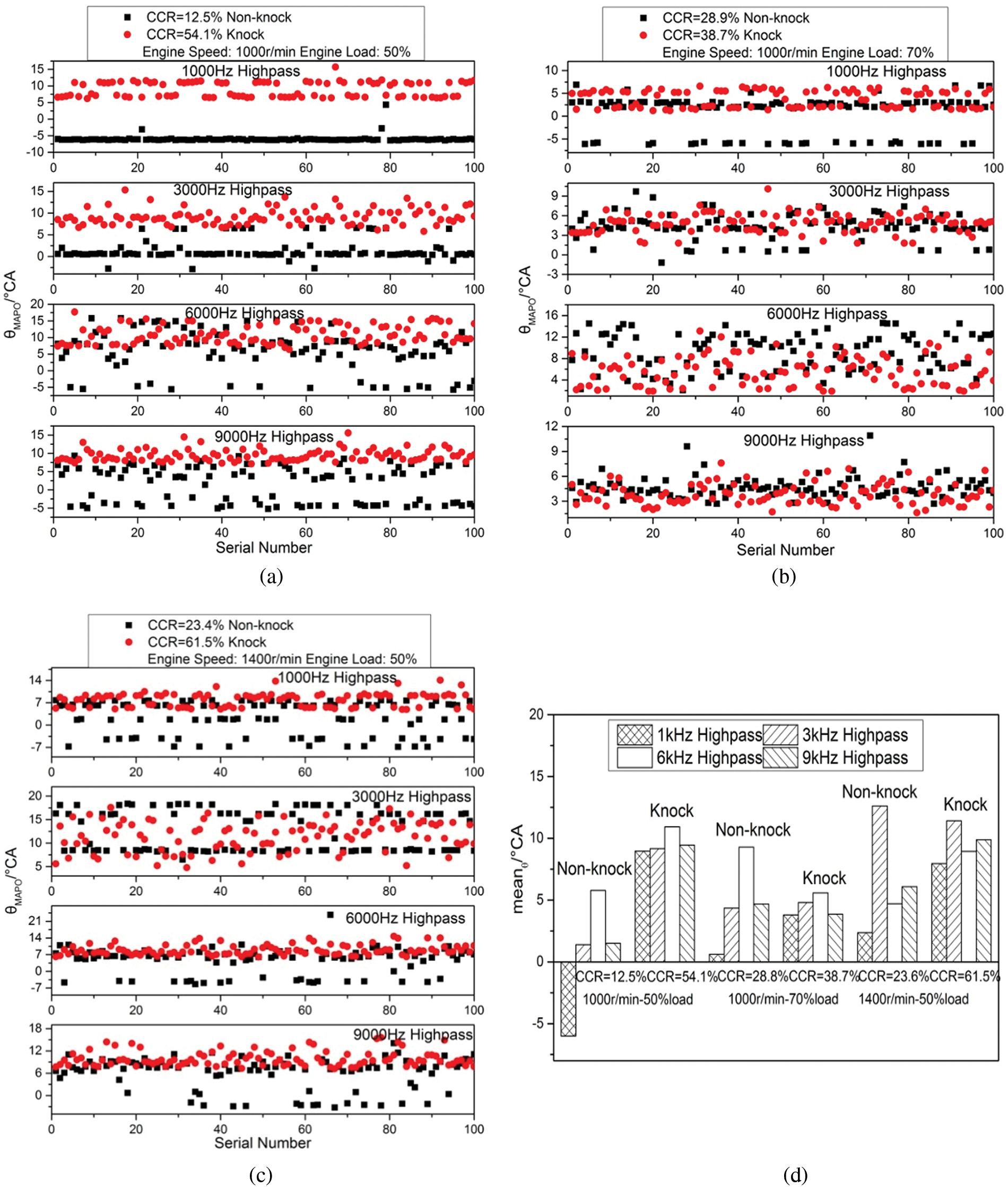
Figure 18: The SUMPOs of double injection mode
In addition, it can be seen at double injection mode, MAPOs at knock state are always larger than at non-knock state, which is different with single injection mode. That is because according to Draper’s acoustic model, the knock combustion pressure oscillation at double injection mode is probably the 4th or 5th propagation mode for its high response frequency. At this propagation mode, the knock combustion starts at more positions and pressure oscillation propagates in a more complex way. The knock pressure oscillations appear near the fire core, then propagate and impact on the pressure wave from fire-core immediately, which cause concentrated pressure oscillation of different frequencies. The high response frequency pressure oscillation power would not loss because of long distance propagation like single injection mode.
Fig. 19 shows the heat release rates of double injection mode. In Fig. 19, the red and black arrows point to the meanθs of knock and non-knock, respectively. SOMI is the abbreviation of start of main injection. It is observed that under knock status, the methanol-air mixture is neither ignited by the pilot diesel nor spontaneously ignites during the pilot injection period even though the mixture is thick with methanol because the first peak of heat release rate changes little and the first heat release period starts to decrease before SOMI. Although the methanol-air mixture does not burn at the first heat release period, the reaction of the methanol-air mixture and the pilot diesel produces a lot of reactive groups, which shortens the ignition delay period of the main injection diesel.

Figure 19: The heat release rates of double injection mode
When the CCR increases to knock, the high content of methanol lowers the activity and temperature of the fuel-air mixture and inhibits the pilot diesel combustion, which leads that only little of pilot injection diesel burns at the pilot injection heat release period and remains a large amount of diesel to burn with the main injection diesel. At the same time, the pilot injection diesel diffuses widely before the main injection, and there has been amount of methanol-diesel-air premixed mixture in the cylinder. These cause that more fuels are involved in the premixed combustion of main injection diesel, and a more concentrated and rapid combustion occurs. At the meantime, the premixed combustion and front half part of diffusion burning becomes more stable because of participation of the unburned pilot diesel and its reactants with methanol, so the pressure signal of knock status is smoother than that of non-knock status at the front half part. However, once the methanol-air mixture auto-ignites and its flame impacts against the flame which propagates to the cylinder wall, the fierce cylinder pressure oscillation occurs and results in the knock.
The main conclusions drawn from this study are shown as follows:
(1) Under knock status, the block vibration of DMDF engine around special frequency band increases greatly, and the frequency bands keep stable with the changes of load and speed. However, the characteristic frequency of knock changes at different diesel injection modes: the characteristic frequency of single injection mode (about 4.1 kHz) is lower than that of double injection mode (about 7–9 kHz).
(2) At both single and double injection, the block vibration PDs at the characteristic frequency bands of knock increase with the increase of engine speed, but keep stable with the change of load.
(3) Under knock status, the amplitude and energy of pressure oscillations are bigger around special frequency bands, and at different diesel injection modes, the frequency bands are different: the frequency band of single injection mode (about 3–6 kHz) is lower than that of double injection mode (about 9 kHz), which corresponds to the characteristic frequency of block vibration. As to knock, the SUMPO is more correlated than MAPO. At the same time, when knock occurs, the positions of pressure oscillations of different frequencies are more concentrated than under non-knock status, and they all centralize in the later stage of combustion.
(4) As for the experiment DMDF engine, the SUMPO threshold value for knock should be set as 700 bar at single injection mode with 1 kHz low-pass cut off frequency and 200 bar at single injection mode with 9 kHz low-pass cut off frequency.
Funding Statement: This research was funded by the Science Research Project of State Grid Shaanxi Electric Power Company (5226 KY22001J), Yulin Science and Technology Planning Project (CXY-2020-024), Natural Science Basic Research Plan of Shaanxi (2018JQ5115, 2020JM-243) and the Special Fund for Basic Scientific Research of Central Colleges, Chang'an University (2018JQ5115).
Conflicts of Interest: The authors declare that they have no conflicts of interest to report regarding the present study.
References
1. Tian, Z., Wang, Y., Zhen, X., Liu, Z. (2022). The effect of methanol production and application in internal combustion engines on emissions in the context of carbon neutrality: A review. Fuel, 320(6), 123902. DOI 10.1016/j.fuel.2022.123902. [Google Scholar] [CrossRef]
2. Zhen, X., Wang, Y. (2015). An overview of methanol as an internal combustion engine fuel. Renewable & Sustainable Energy Reviews, 52(2), 477–493. DOI 10.1016/j.rser.2015.07.083. [Google Scholar] [CrossRef]
3. Sayin, C. (2010). Engine performance and exhaust gas emissions of methanol and ethanol-diesel blends. Fuel, 89(11), 3410–3415. DOI 10.1016/j.fuel.2010.02.017. [Google Scholar] [CrossRef]
4. Sayin, C., Ozsezen, A. N., Canakci, M. (2010). The influence of operating parameters on the performance and emissions of a di diesel engine using methanol-blended-diesel fuel. Fuel, 89(7), 1407–1414. DOI 10.1016/j.fuel.2009.10.035. [Google Scholar] [CrossRef]
5. Sayin, C., Ilhan, M., Canakci, M., Gumus, M. (2009). Effect of injection timing on the exhaust emissions of a diesel engine using diesel-methanol blends. Renewable Energy, 34(5), 1261–1269. DOI 10.1016/j.renene.2008.10.010. [Google Scholar] [CrossRef]
6. Wei, H., Yao, C., Pan, W., Han, G., Dou, Z. (2017). Experimental investigations of the effects of pilot injection on combustion and gaseous emission characteristics of diesel/methanol dual fuel engine. Fuel, 188, 427–441. DOI 10.1016/j.fuel.2016.10.056. [Google Scholar] [CrossRef]
7. Peng, G., Yao, C., Wei, L., Liu, J., Wang, Q. (2014). Reduction of pm emissions from a heavy-duty diesel engine with diesel/methanol dual fuel. Fuel, 123, 1–11. DOI 10.1016/j.fuel.2014.01.056. [Google Scholar] [CrossRef]
8. Chen, Z., Yao, C., Wang, Q., Han, G., Dou, Z. (2016). Study of cylinder-to-cylinder variation in a diesel engine fueled with diesel/methanol dual fuel. Fuel, 170(5), 67–76. DOI 10.1016/j.fuel.2015.12.019. [Google Scholar] [CrossRef]
9. Yao, C., Pan, W., Yao, A. (2017). Methanol fumigation in compression-ignition engines: A critical review of recent academic and technological developments. Fuel, 209, 713–732. DOI 10.1016/j.fuel.2017.08.038. [Google Scholar] [CrossRef]
10. Chen, Z., He, J., Chen, H., Geng, L., Zhang, P. (2021). Comparative study on the combustion and emissions of dual-fuel common rail engines fueled with diesel/methanol, diesel/ethanol, and diesel/n-butanol. Fuel, 304, 121360. DOI 10.1016/j.fuel.2021.121360. [Google Scholar] [CrossRef]
11. Zhen, X., Wang, Y., Xu, S., Zhu, Y., Tao, C. et al. (2012). The engine knock analysis–An overview. Applied Energy, 92(2), 628–636. DOI 10.1016/j.apenergy.2011.11.079. [Google Scholar] [CrossRef]
12. Zhou, D. Z., Yang, W. M., An, H. (2015). Application of CFD-chemical kinetics approach in detecting rcci engine knocking fuelled with biodiesel/methanol. Applied Energy, 145, 255–264. DOI 10.1016/j.apenergy.2015.02.058. [Google Scholar] [CrossRef]
13. Lounici, M. S., Benbellil, M. A., Loubar, K., Niculescu, D. C. (2017). Knock characterization and development of a new knock indicator for dual-fuel engines. Energy, 141, 2351–2361. DOI 10.1016/j.energy.2017.11.138. [Google Scholar] [CrossRef]
14. Szwaja, S., Naber, J. D. (2013). Dual nature of hydrogen combustion knock. International Journal of Hydrogen Energy, 38(28), 12489–12496. DOI 10.1016/j.ijhydene.2013.07.036. [Google Scholar] [CrossRef]
15. Wei, H., Feng, D., Pan, M., Pan, J., Rao, X. et al. (2016). Experimental investigation on the knocking combustion characteristics of n-butanol gasoline blends in a DISI engine. Applied Energy, 175(3), 346–355. DOI 10.1016/j.apenergy.2016.05.029. [Google Scholar] [CrossRef]
16. Siano, D., Panza, M. A., D’Agostino, D. (2015). Knock detection based on MAPO analysis, AR model and discrete wavelet transformation applied to the in-cylinder pressure data: Results and comparison. Sae International Journal of Engines, 8, 1–13. [Google Scholar]
17. Brecq, G., Bellettre, J., Tazerout, M. (2003). A new indicator for knock detection in gas SI engines. International Journal of Thermal Sciences, 42(5), 523–532. DOI 10.1016/S1290-0729(02)00052-2. [Google Scholar] [CrossRef]
18. Liu, L., Wu, Y., Wang, Y. (2022). Numerical investigation on knock characteristics and mechanism of large-bore natural gas dual-fuel marine engine. Fuel, 310(2), 122298. DOI 10.1016/j.fuel.2021.122298. [Google Scholar] [CrossRef]
19. Wang, Y., Guo, C., Wang, P., Wang, D. (2019). Numerical investigation on knock combustion in a diesel-dimethyl ether dual-fuel engine. Energy & Fuels, 33(6), 5710–5718. DOI 10.1021/acs.energyfuels.9b00695. [Google Scholar] [CrossRef]
20. Wang, H. Y., Gan, H. B., Theotokatos, G. (2020). Parametric investigation of pre-injection on the combustion, knocking and emissions behaviour of a large marine four-stroke dual-fuel engine. Fuel, 281, 118744. [Google Scholar]
21. Jiang, A., Li, X., Huang, X., Zhang, Z. (2008). Detection of engine misfire by wavelet analysis of cylinder-head vibration signals. International Journal of Agricultural & Biological Engineering, 1(2), 1–7. [Google Scholar]
22. Siano, D., D’Agostino, D. (2015). Knock detection in SI engines by using the discrete wavelet transform of the engine block vibrational signals. Energy Procedia, 81, 673–688. DOI 10.1016/j.egypro.2015.12.052. [Google Scholar] [CrossRef]
23. Draper, C. S. (1938). Pressure waves accompanying detonation in the internal combustion engine. Journal of the Aeronautical Sciences, 5(6), 219–226. DOI 10.2514/8.590. [Google Scholar] [CrossRef]
24. Yoshizawa, K., Teraji, A., Miyakubo, H., Koichi, Y., Tomonori, U. (2006). Study of high load operation limit expansion for gasoline compression ignition engines. Journal of Engineering for Gas Turbines and Power, 128(2), 377–387. DOI 10.1115/1.1805548. [Google Scholar] [CrossRef]
25. Andreae, M. M., Cheng, W. K., Kenney, T., Yang, J. (2007). On HCCI engine knock. Shanghai, China: SAE International Fuels & Lubricants Meeting. [Google Scholar]
Cite This Article
 Copyright © 2023 The Author(s). Published by Tech Science Press.
This work is licensed under a Creative Commons Attribution 4.0 International License , which permits unrestricted use, distribution, and reproduction in any medium, provided the original work is properly cited.
 Downloads
 Citation Tools