
 Submit a Paper
 Propose a Special lssue
 Open Access
ARTICLE

Harmonic State-Space Based AC-Side Impedance Model of MMC and High Frequency Oscillation Characteristics Analysis
1 State Grid Chongqing Electric Power Company Research Institute, Chongqing, 401120, China
2 Key Laboratory of Modern Power System Simulation and Control & Renewable Energy Technology (Northeast Electric Power University), Jilin, 132012, China
* Corresponding Author: Haozheng Wang. Email:
Energy Engineering 2023, 120(4), 831-850. https://doi.org/10.32604/ee.2023.025171
Received 25 June 2022; Accepted 14 September 2022; Issue published 13 February 2023
 View Full Text
 Download PDF
Abstract
Recently, high-frequency oscillation of the modular multilevel converter (MMC) based high-voltage direct current (HVDC) projects has attracted great attentions. In order to analyze the small-signal stability, this paper uses the harmonic state-space (HSS) method to establish a detailed frequency domain impedance model of the AC-side of the HVDC transmission system, which considers the internal dynamic characteristics. In addition, the suggested model is also used to assess the system's high-frequency oscillation mechanism, and the effects of the MMC current inner loop control, feedforward voltage links, and control delay on the high-frequency impedance characteristics and the effect of higher harmonic components. Finally, three oscillation suppression schemes are analyzed for the oscillation problems occurring in actual engineering, and a simplified impedance model considering only the high-frequency impedance characteristics is established to compare the suppression effect with the detailed impedance model to prove its reliability.Keywords
Nomenclature
| HVDC | High voltage direct current |
| MMC | Modular multilevel converter |
| HSS | Harmonic state-space |
| PLL | Phase-locked loop |
| CCSC | Circulating current suppressing control |
| AC | Direct current |
| DC | Alternating current |
| IGBT | Insulated gate bipolar transistor |
| Abbreviations | |
| vg | Rated AC-side voltage |
| vdc | Rated DC-side voltage |
| vcu | Sum of the capacitance voltages of the upper bridge arms |
| vcl | Sum of the capacitance voltages of the lower bridge arms |
| iu | Currents flowing through the upper bridge arms |
| il | Currents flowing through the lower bridge arms |
| ic | Circulating current |
| ig | AC-side phase current |
| N | Amount of submodule |
| C | Capacitance of submodule |
| R0 | Arm resistor |
| L0 | Arm inductance |
| su | Upper bridge arms modulation function |
| sl | Lower bridge arms modulation function |
| Kinp | Current inner loop PI controller scale coefficients |
| Kini | Current inner loop PI controller integration coefficients |
| Kcirp | CCSC PI controller scale coefficients |
| Kciri | CCSC PI controller integration coefficients |
| Gy | Control delay link |
| Td | Delay time |
| Kf | Feedforward voltage coefficient |
Modular multilevel converter based high voltage direct current (MMC-HVDC) transmission has been widely used in the fields of new energy generation interconnection, high voltage and large capacity transmission and asynchronous grid interconnection thanks to its advantages of low harmonic content, flexible structure, high controllability, and no phase change failure [1–3]. However, the variable current device of the MMC-HVDC contains large-scale power electronics, and there are many control links and the characteristics of the interaction between the AC and DC sides, which also introduces new stability problems [4]. In recent years, low-frequency oscillation (<100 Hz) [5], medium-frequency oscillation (100~1 kHz) [6] and high-frequency oscillation (>1 kHz) [7] events have occurred during the commissioning and operation of several MMC-HVDC projects in the world. There are relatively mature stability analysis and suppression methods related to low and medium-frequency oscillations. In contrast, high-frequency oscillation issues have only emerged in recent years, such as the 1.2 kHz high-frequency oscillation that occurred in the Luxi Back-to-Back HVDC project [8] and the 1.8 kHz high-frequency oscillation that occurred during the commissioning of the Chongqing-Hubei Back-to-Back HVDC Project [9].
These oscillation situations are excited under certain operating conditions and can be attributed to small disturbance problems. The impedance analysis method can be used to analyze this oscillation stability problem due to its clear physical meaning and explanation of the oscillation mechanism. Building the MMC high-frequency small-signal model under frequency domain response is the key to studying the high-frequency oscillation problem. The main methods for building the MMC small-signal model are the harmonic linearization method [10], dynamic phase volume method [11], multi-harmonic linearization method [12] and the harmonic state-space method [13,14]. In [10], the harmonic linearization method was applied to establish the sequential impedance model of MMC, but the method is more suitable for studying a single high-frequency band oscillation problem, which cannot represent the system-wide band impedance characteristics well. Although the model structure is simple, it cannot be extended to higher harmonics. In [14], the HSS modelling approach was adopted to consider the effect of zero-sequence voltage on MMC mainly acting in the low-frequency band below 100 Hz, which can be disregarded for stability analysis in the high-frequency band. Literature [15] indicated that the HSS model has a very high-order system state matrix, which consequently imposes a high computational burden for the stability analysis. In order to capture the frequency-coupling dynamics of unbalanced three-phase power systems, the model derivation process is complicated with the increased system order. However, the literature does not consider the effect of higher harmonics on the MMC broadband impedance characteristics and the necessity of the HSS model in the analysis of the small signal stability of the MMC. Furthermore, literature [16] demonstrates that the outer control loop, phase-locked loop (PLL), circulating current suppressing control (CCSC), and dynamics within the MMC have less influence on the MMC high-frequency impedance characteristics. And the simplified high-frequency model that neglects control parts other than the current inner loop, control delay, and feedforward voltage has been widely used to analyze high-frequency oscillation problems. A method was proposed in [17] that the additional low-pass filter in the voltage feedforward link and the additional AC filter on the AC-side can effectively suppress high-frequency oscillations, but this method in practical engineering can cause new oscillation phenomena in other frequency bands. In [18], a damping suppression strategy based on the idea of a virtual impedance with active shaping has been proposed. Combined with low-pass filtering, it can eliminate the original band oscillations and the newly introduced oscillations well, but this strategy has a low tolerance to model errors and is unsuitable for engineering applications. In [19], a control link optimization strategy of attaching low-pass filters to the proportional links of the voltage supply loop and the current loop is proposed to reduce the high-frequency negative damping generated by the control delay.
In this paper, to address the above problems, the high-frequency oscillation problems in the MMC-HVDC system are studied through modelling-simulation-verification-characterization-analysis-suppression strategies of the system. Chapter 2 first establishes a steady-state model in the time domain of the system. Then, the HSS method is used to establish a broadband impedance model of the system, considering the harmonic coupling characteristics. Chapter 3 compares the model with the electromagnetic simulation model to verify and reveal the effects of higher harmonic components, current inner loop control, feedforward voltage link, and control delay link on the AC-side impedance characteristics of MMC and then analyzes the high-frequency oscillation mechanism. Chapter 4 combines the simplified high-frequency model to obtain the suppression results of three strategies for the high-frequency oscillation problem and analyzes in detail the effect of each strategy on the system impedance characteristics.
2 HSS Based Detailed Impedance Model of MMC
2.1 MMC Steady-State Time Domain Model Construction
The small signal model of MMC considering harmonic coupling characteristics in this paper belongs to multi-frequency modeling but is different from the general multi-frequency modeling of DC/DC converters, which is a broader concept than the modeling of harmonic interaction characteristics. Multi-frequency modeling of DC/DC converters is to fully consider the sideband effects caused by the switching frequency coupling, so that the model can accurately describe the dynamic response of the frequency band above one-half of the switching frequency. The purpose of the model proposed in this paper is to consider the interaction of different harmonic components in the internal dynamics of the MMC. The difference between the two is shown in Fig. 1:
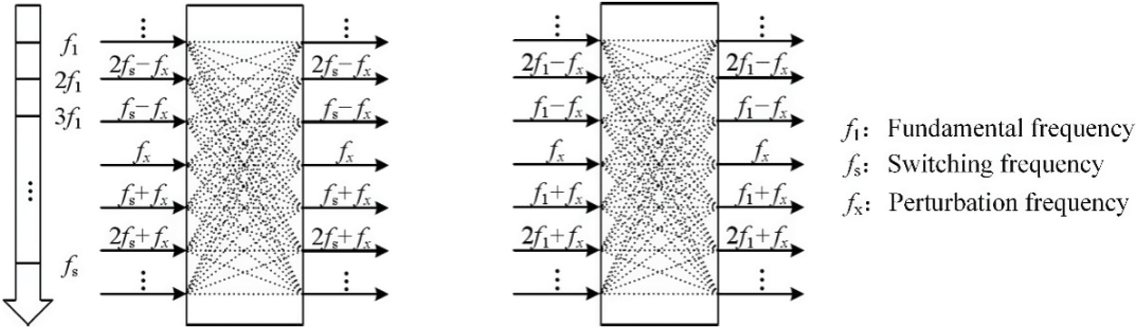
Figure 1: Comparison of different multi-frequency modeling
A MMC-HVDC system’s main structure topology is shown in Fig. 2. The entire converter consists of a three-phase circuit, with each phase consisting of two bridge arms, upper and lower, each containing N half-bridge sub-modules.

Figure 2: HVDC transmission system structure
If the actual semiconductor switch model is used for each sub-module, the model order will be very high and computationally complex, which is difficult to use in the controller design of MMC. In order to design the MMC’s internal controller, the differences between the individual submodules within each bridge arm can be ignored. The bridge arm averaging model assumes that all sub-modules on the same bridge arm have identical states, thus equating all sub-modules within the bridge arm to a combined DC voltage and current source, greatly simplifying the complexity of the model. The bridge arm averaging model reflects the structural relationship between the bridge arms, ignores the switching dynamics in the MMC, and is a continuous time system model, while preserving the dynamic interactions within the MMC, and is often used as the basic time-domain model in modeling the small signal dynamics of the MMC. In this paper, this model is used to model the MMC based on the system level, ignoring the switching frequency and its sideband harmonics, and approximating that the sum of the switching functions S of all submodules in each phase bridge arm is equal to the modulated wave s of the bridge arm.
By averaging the bridge arms, the mathematical model of the MMC is simplified to twelve orders, corresponding to the inductance of the six bridge arms and the capacitance of the averaged submodules of the six bridge arms. An equivalent bridge arm impedance can be expressed as Z0 = R0 + L0. The MMC single-phase averaging equivalent model is shown in Fig. 3. In the figure, vdc is the dc voltage; vg is the AC-side phase voltage; vcu and vcl represent the sum of the capacitance voltages of the upper and lower bridge arms, respectively; iu and il are the currents flowing through the upper and lower bridge arms, respectively; ic is the circulating current; ig is the AC-side phase current; C is the sub-module capacitance, Carm is the equivalent bridge arm capacitance, and the calculation formula: Carm = C/N.
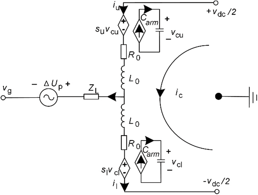
Figure 3: MMC single-phase equivalent circuit structure
The MMC time-domain three-phase state-space expression after perturbation linearization can be obtained from Fig. 3 as:
The variables in the formula are all three-phase (x = a,b,c) periodic time-varying signals, and the superscript s represents the steady-state operating point. The modulation function su, sl is also obtained by the MMC control system.
where
In the MMC transmission system interconnection scenario with the grid, the complete control is shown in Fig. 4. In order to reflect the effect of the control delay on system oscillations, an overall delay link is added between the system’s nearest level approximation modulation and the modulating wave generated by the control system.
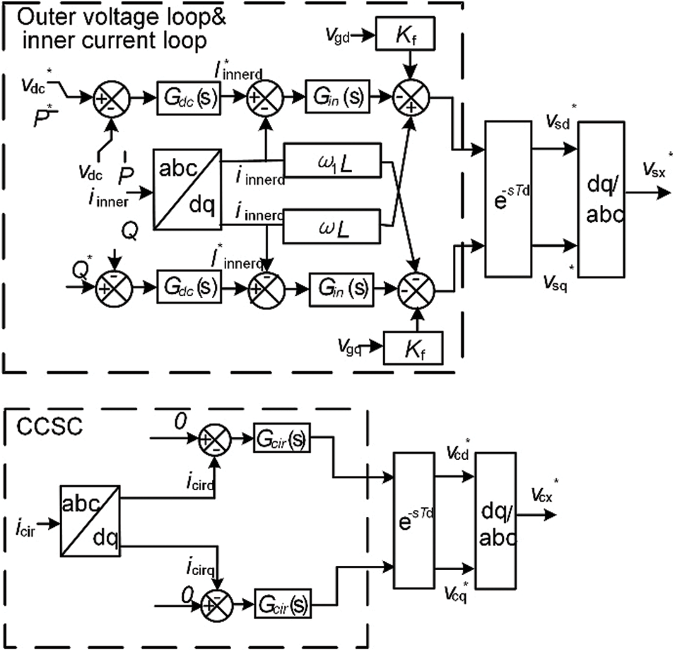
Figure 4: MMC control system block diagram
From the control system block diagram, the specific form of the fundamental frequency modulation voltage and the two-fold modulation voltage can be obtained as:
where Kinp and Kini denote the current inner loop PI controller scale and integration coefficients; Kcirp and Kciri denote the CCSC PI controller scale and integration coefficients, respectively; xidq and xcdq denote the current inner loop and CCSC integrators; Gy denotes the control delay link; Kf denotes the feedforward voltage coefficient; Kid denotes the current inner loop cross-decoupling compensation term; Kcd denotes the CCSC cross-decoupling compensation term.
The linear model of the control section is based on a d-q rotating coordinate system. In order to interface with the MMC main circuit model in the three-phase stationary coordinate system, it is necessary to perform the Park transform as well as the inverse transform to obtain its three-phase output form. The three-phase form of the fundamental frequency voltage and the two-fold frequency voltage is obtained as:
where n1 and n2 are constant matrices used to implement the coordinate transformation, and the state variables introduced by the control integrator can be expressed as:
The three-phase linear state-space model of the MMC is obtained by associating the control system model with the main circuit model.
2.2 MMC Frequency Domain Model Construction
According to the theoretical derivation in Section 2, MMC is a periodic time-varying system with no fixed DC steady-state operating point. In this regard, this section will use the method of harmonic state-space to realize the time domain to frequency domain transformation. The Fourier transform can convert any continuous periodic signal into frequency domain form as shown in Eq. (9).
Substituting Eq. (9) into Eq. (8), the HSS based MMC frequency domain model can be obtained after simplification as shown in Eq. (10).
where N represents the diagonal matrix, the diagonal elements contain the frequency information; A and B matrices are of the same form and both are Toeplitz matrices; the subscripts represent the Fourier levels. The MMC contains an infinite number of harmonics due to its frequency interaction characteristics. However, in its actual operation, the amplitude of the 3rd and higher harmonics is usually small and almost negligible compared to the first three harmonics. Therefore, only the first three harmonics are considered in this example's model constructed for the MMC. The forms of the matrix A, N and X matrices are shown in Eqs. (11) to (13), respectively.
where the elements in the A matrix are also a matrix of the same size as A(t). The number of steps is 126.
When the MMC operates in a steady state, the complex variable s of the HSS model tends to zero, so the inverse of Eq. (13) can establish the relationship between the state variable and the output variable. The output variable contains the external disturbance voltage of the AC-side; the state variable contains the response current of the AC-side, and the AC-side impedance can be calculated by dividing the two.
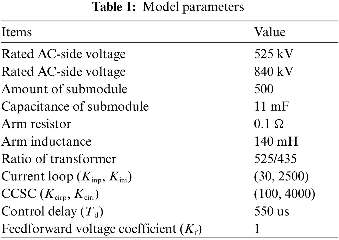
The main parameters of the system are shown in Table 1.
In order to verify the correctness of the established impedance model, the equivalent impedance characteristics of the MMC are obtained by the impedance scanning method in the PSCAD electromagnetic transient simulation platform. The MMC electromagnetic transient model with corresponding parameters is connected to the AC power grid mentioned later in the paper.
The principle of impedance measurement is that: first detect the voltage and current on the equipment to be measured when there is no perturbation injection; then, a small perturbation voltage is injected into the system to be measured, and the system to be measured will produce the corresponding current response; finally, the voltage perturbation and current response at the input interface of the power electronic equipment to be measured are detected and subtracted from the voltage and current on the equipment to be measured without perturbation injection. The impedance at the perturbation frequency can be calculated based on the voltage and current difference at the perturbation frequency. The swept frequency result is compared with the calculated result of the method in this paper, and the comparison graph is shown in the Fig. 5.
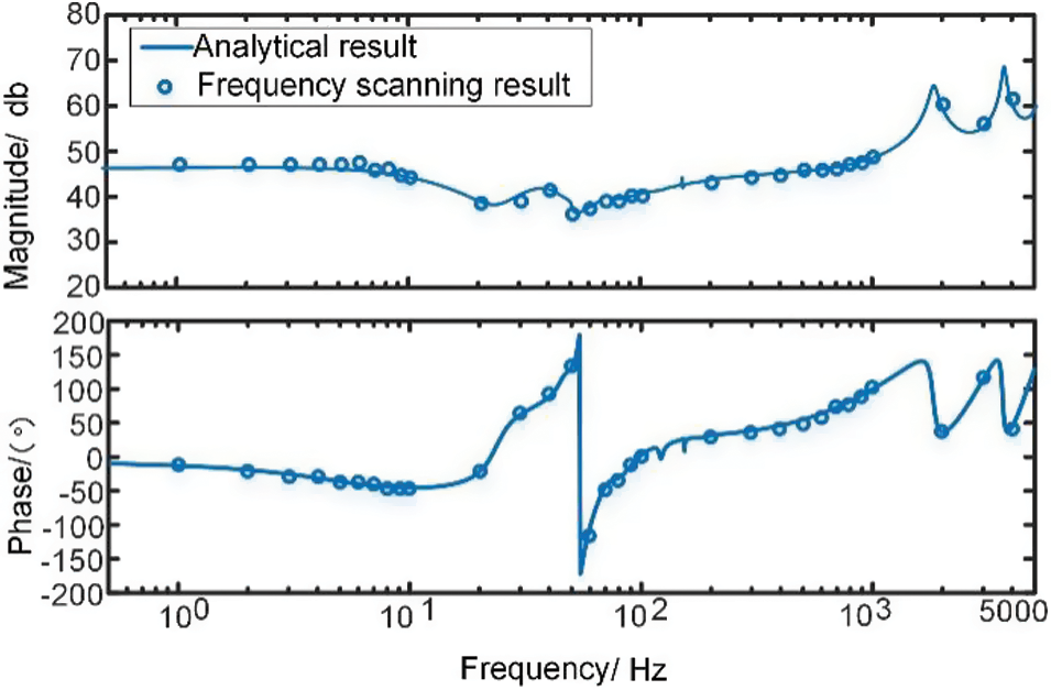
Figure 5: Model validation diagram
The result shows that the theoretical model and the frequency scanning results are basically consistent, which proves that the model built has high accuracy and can be used to analyze the stability problem.
3.2 Effect of Higher Harmonic Components on the Impedance Characteristics of MMC
With the help of the Toplitz matrix, the HSS modeling can be more easily programmed modularly and include the higher harmonic dynamics in the model. Theoretically, HSS modeling includes infinite harmonic dynamics, but due to the presence of inductors, the amplitude of ultra-high harmonics is small, so truncation of finite model order is usually performed. When considering the higher harmonics, the effect of the third and higher harmonics on the impedance characteristics of MMC is shown in Fig. 6.
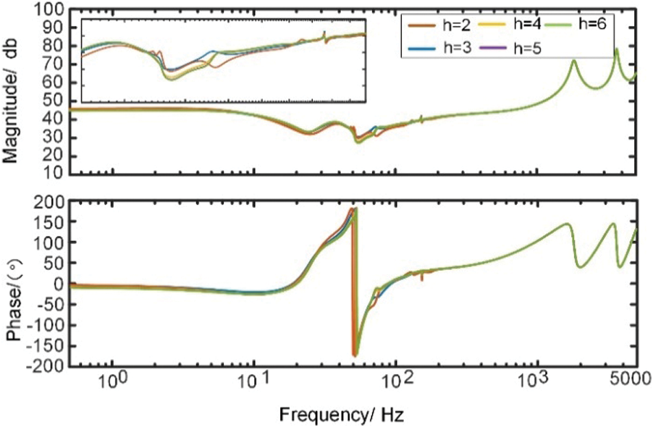
Figure 6: Comparison of HSS models of different orders
As seen from the figure, the HSS model considering the second harmonic can describe the frequency response of the MMC more accurately, and the HSS model considering the fifth and sixth harmonics remains basically the same. From the impedance characteristics, it can be seen that the effect of higher harmonics on the frequency response is still mainly in the low and middle-frequency band (10–200 Hz). This shows that the HSS method greatly benefits studying oscillations over a wide-frequency range because he can easily consider the higher harmonics. The HSS method is more accurate when analyzing an oscillation problem in the 10 to 200 Hz frequency band due to the problem of insufficient phase margin. When considering the higher harmonics, the impedance characteristics at the intersection of the 60 Hz impedance amplitude-frequency characteristics shown in Fig. 7 can clearly reflect the small-signal instability that may be caused by the improper selection of the system control parameters, while considering only the lower harmonics may lead to wrong conclusions. The LTI model will become highly complicated when analyzing such problems.
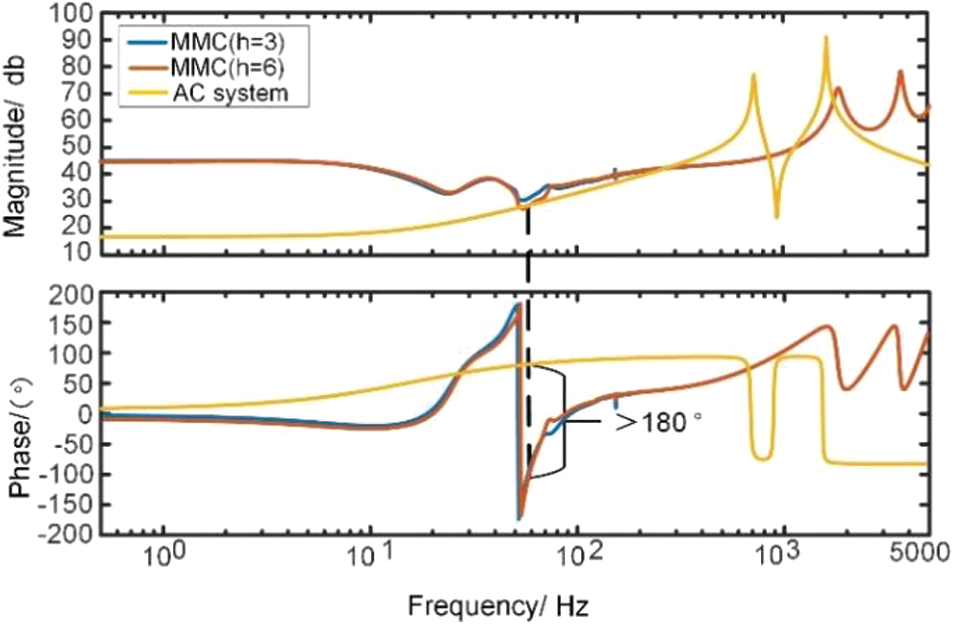
Figure 7: Medium frequency oscillation phenomenon when considering high harmonics
However, it is not necessary to consider high harmonic interactions in the analysis of the stability of all frequency bands. For example, in the analysis of low and high-frequency bands, the influence of the higher harmonic components is smaller, and the dynamic characteristics of the high-frequency can be accurately described by considering only the harmonic components within the third order. Therefore, models of different orders can be used when targeting different stability problems.
3.3 MMC High-Frequency Impedance Characteristics Analysis
According to the detailed impedance model, analyzing the law of the influence of each link, it can be obtained that the high-frequency impedance characteristics of the AC-side of the system are mainly influenced by the current inner loop, the feedforward voltage, and the control delay.
3.3.1 Effect of Current Inner Loop
Different inner-loop control parameters are designed for AC-side impedance analysis. Fig. 8 shows the impedance characteristics of the MMC.
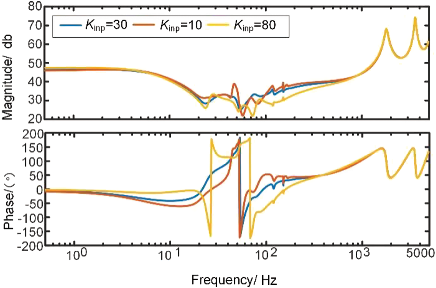
Figure 8: Effect of current inner loop
When changing the current inner loop scale factor, the amplitude-frequency and phase-frequency characteristics of the frequency band below 1000 Hz change more obviously, and the resonance degree increases when kinp increases, but the effect on the characteristics of the high-frequency band above 1000 Hz is small, and the effect on high-frequency oscillation is not significant.
3.3.2 Effect of Feedforward Voltage Link
Similar to the analysis of the current inner control, the effect of the feedforward voltage link on the AC-side impedance characteristics of the system is analyzed as shown in Fig. 9.
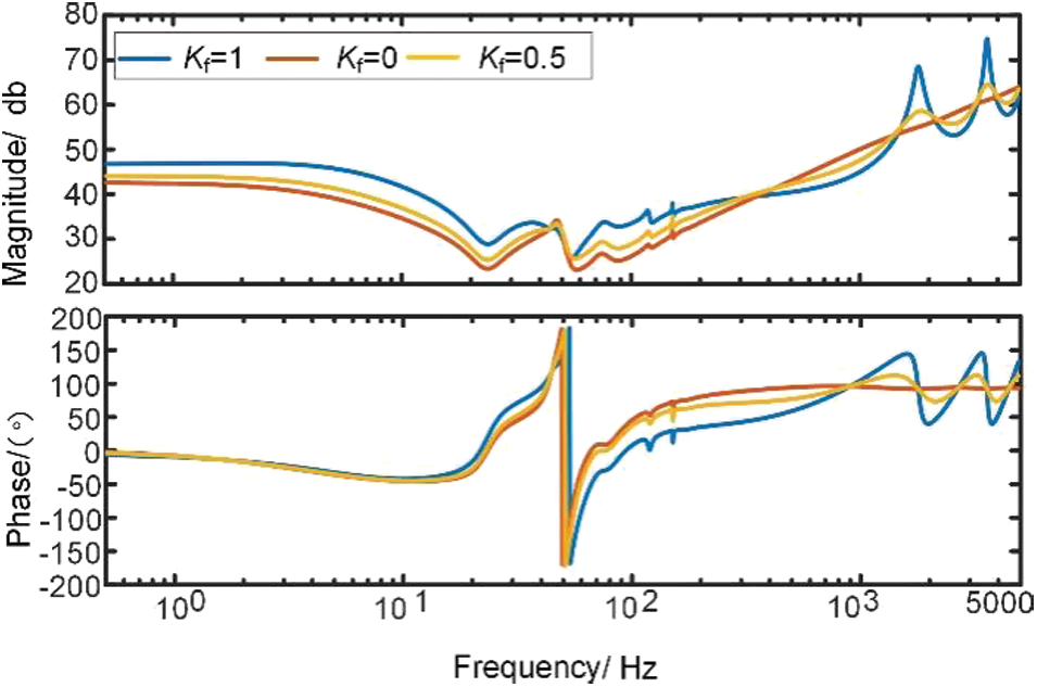
Figure 9: Effect of feedforward voltage link
It can be seen from the figure, the impedance amplitude-frequency and phase-frequency characteristics are minimally affected by the feedforward voltage link in the low and medium frequency bands; as the coefficient Kf rises, the effect on the high-frequency impedance characteristics increases and is more likely to cause stability problems. The MMC impedance characteristics are best when there is no feedforward voltage, but the feedforward voltage link can improve the fault ride-through capability and prevent overcurrent during a system fault, significantly improving the system's transient stability while reducing the system's small disturbance stability.
In order to study the effect of control delay on the impedance characteristics of the MMC, a delay link e−sTd is added to the control system during stable operation, and the delay time Td is gradually increased. The impedance characteristics of the AC-side are shown in Fig. 10.
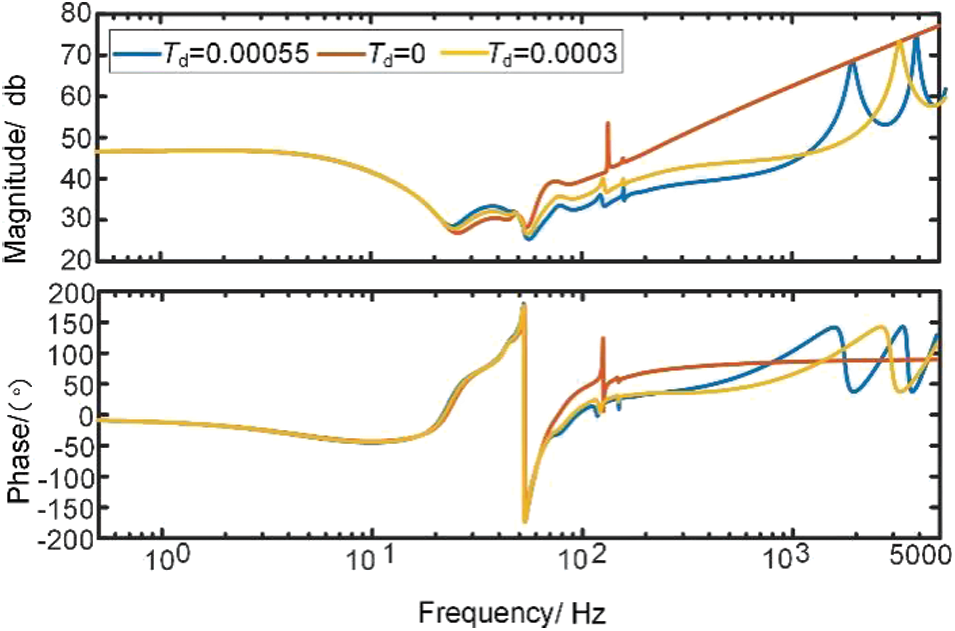
Figure 10: Effect of control delay
After adding the delay link, it can be seen that the control delay mainly affects the high-frequency impedance characteristics in the system and has little effect on the low and medium frequencies. As the delay time changes, the characteristics change, which may lead to high-frequency oscillations in the system.
4 Study of Suppression Strategies
For the actual high-frequency oscillation problem, the impedance analysis method is used to analyze its stability. The equivalent sequential impedance model is shown in Fig. 11, where the MMC-HVDC system is equivalent to the DC current source In and impedance Zn, and the AC system is equivalent to the DC voltage source Uz and impedance Zz.
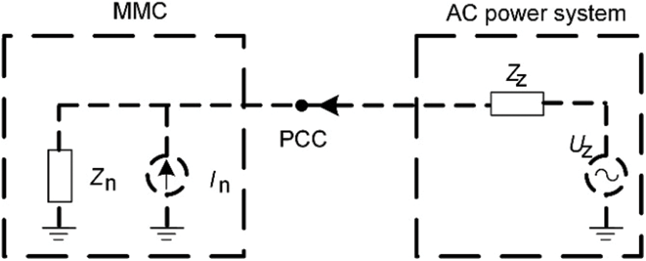
Figure 11: MMC connection ac system equivalent circuit diagram
According to Kirchhoff's law and linear control theory, it can be obtained that the system is stable when Zz and Zn satisfy the amplitude-frequency and phase-frequency characteristics. Therefore, the stability problem can be analyzed by the relationship between the impedance forms of the double-ended converter station. From the above stability discrimination principle, in order to further analyze the high-frequency resonance problem in MMC, this paper equates the AC system impedance by connecting two RL and C parallel circuits in series, as shown in Fig. 12.

Figure 12: Equivalent AC systems
where L1 = 5 mH, R1 = 5
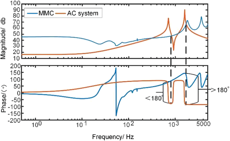
Figure 13: Oscillation case reappears
According to the figure, approaches for suppressing oscillations fall into two primary categories: one is to make the impedance amplitude of the two systems without intersection, and the other is to make the phase difference at the intersection less than 180°. Given that numerous impedance poles exist in the AC line, it is not easy to produce impedance without intersection using the first approach, so we must begin with the second.
4.1 Second-Order Low-Pass Filter Suppression
The low-pass filter suppression strategy is to set up a filter or quasi-proportional resonance link in the feedforward channel to dampen the high-frequency signal through the attenuation effect of the filter in the high-frequency band. The transfer function of the filter, Gf (s), is obtained as:
where
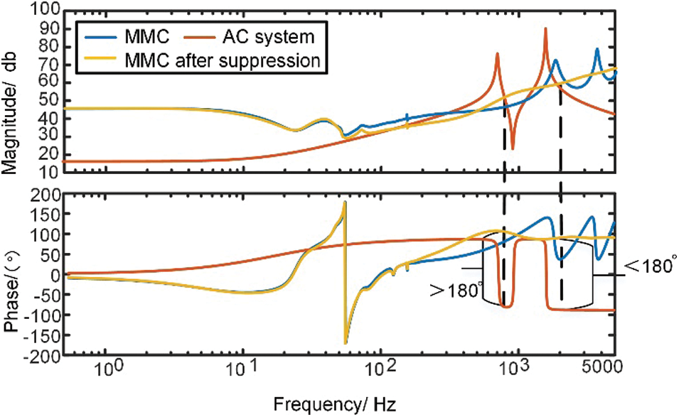
Figure 14: Second-order low-pass filter suppression before and after comparison chart
When the model does not consider the dynamic within MMC, the control link only considers the current inner loop control, feedforward voltage, and control delay link, the simplified impedance model Zjh is obtained as:
where R0 = 2R′, L0 = 2L′, Ts is the delay time, and
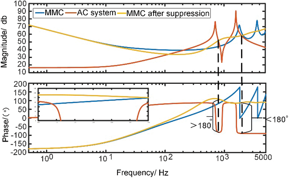
Figure 15: Simplified model second-order low-pass filter suppression before and after comparison chart
It can also be seen from the figure that when the feedforward voltage is introduced to the low-pass filter, the resonant spikes and negative damping characteristics in the high-frequency band of the impedance characteristic curve vanish, while the negative damping band shifts toward the middle frequency. It can be seen that the low-pass filter helps attenuate the high-frequency oscillation characteristics induced by the feedforward voltage and reduces the negative damping band range, but it cannot completely eliminate the negative damping. A project that uses a low-pass filter to suppress the 1700 Hz high-frequency oscillation phenomenon, and after the suppression is completed, a new 800 Hz oscillation phenomenon appears, so it is still necessary to suppress the negative damping of MMC impedance in multiple oscillation risk bands.
4.2 Active Damping Suppression
Active damping suppression is an additional control strategy used to improve the damping of a specific frequency band. It is typically employed in conjunction with feedforward voltage low-pass filtering. The principle is to superimpose the feedforward voltage transients with the reference current using a first-order high-pass filter link in series with two first-order low-pass filter links to form a third-order dampener. They are then superimposed into the reference voltage. The expression Gdamp is obtained as:
where fH, fL1, and fL2 are the passbands of the high-pass filter and the two low-pass filters, respectively; kS is the gain coefficient. The principle of parameter design is based on the need to know precisely the range of variation of the impedance characteristic of the AC system. The design process is as follows: first, the initial range and step size of the additional damping controller parameters are given, and the upper and lower cutoff frequencies are calculated; then, the parameters whose cutoff frequencies meet the conditions are sorted to obtain the stability domain of the damping controller parameters; finally, the stability domain parameters are introduced into the MMC impedance model to judge whether the oscillation can be suppressed, and the simulation is carried out in the electromagnetic transient model to check its effectiveness. Changing the parameters of the damping controller to adjust the impedance will show the phenomenon of “ebb and flow”, so that the phase difference at the resonance point is less than 180° to avoid the occurrence of high-frequency oscillation. Considering the impedance characteristics, the parameters of the additional damping controller are fH = 30 Hz; fL1 = 300 Hz; fL2 = 1000 Hz; kS = 0.035, and the effect of parameter variation on the impedance characteristics of MMC is shown in Fig. 16.
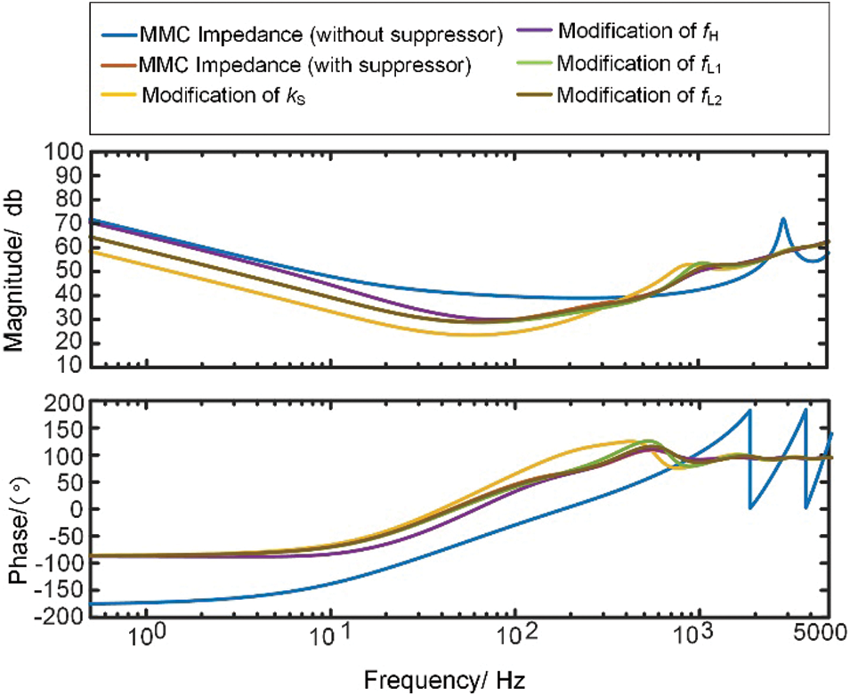
Figure 16: Effect of active damping suppression parameter changes on MMC stability
The effect of active damping suppression on the suppression of high-frequency oscillations of the system analyzed under the optimal parameters is shown in Fig. 17.
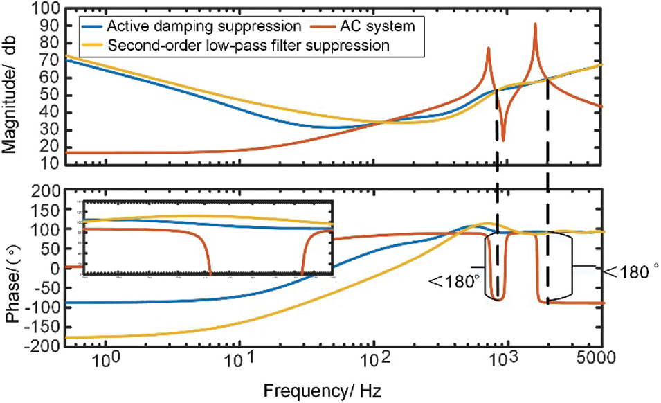
Figure 17: Simplified model active damping suppression before and after comparison chart
As seen in the figure, the phase angle of the impedance around 0.7 and 1.8 kHz can be coordinated and balanced by using an additional active damping rejection to suppress high-frequency oscillations. However, the high-frequency band of the MMC still has negative damping when the network is capacitive, and the risk of oscillation is not completely eliminated.
The control link optimization enhances the system stability by improving the existing control links. Based on the voltage anticipation low-pass filter, an optimized control structure strategy with a low-pass filter in the proportional current loop link is used to reduce the high-frequency negative damping caused by the control delay. The variable parameters of this strategy include the cutoff frequency of the proportional low-pass filter in the current loop and the cutoff frequency of the voltage anticipation low-pass filter. The impedance characteristics of this parameter are shown in Fig. 18.
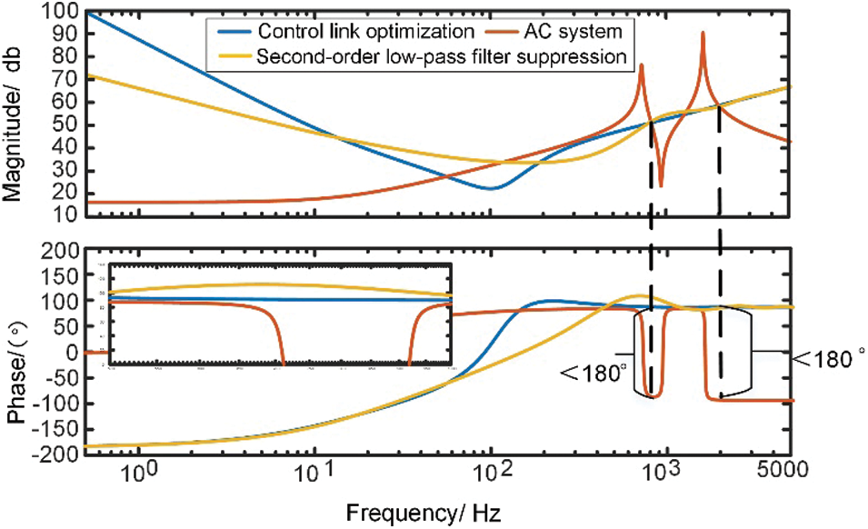
Figure 18: Simplified model control link optimization before and after comparison chart
From the figure, the control link optimization strategy can suppress the oscillations near 1.8 kHz and 700 Hz that occur in the system with proper parameter adjustment but still cannot completely eliminate the negative damping band.
High-frequency oscillation problem of the MMC-HVDC transmission system is becoming increasingly noticeable. This study examines the high-frequency oscillation mechanism and the effects of some factors on the MMC AC-side impedance characteristics. Three oscillation suppression strategies are studied in comparison, and a simplified and accurate high-frequency impedance model of MMC is established for the analysis of high-frequency oscillation problems. The following conclusions are obtained:
1) The effect of higher harmonics on the frequency response is still mainly in the low and middle-frequency band (10–200 Hz), and the dynamic characteristics of the high-frequency can be accurately described by considering only the harmonic components within the third order. The analysis of MMC small signal stability needs to be extended to the wide-frequency range in the future. The HSS model is essential in analyzing the negative damping transfer to the low-frequency band due to the high-frequency suppression strategy and the suppression of oscillation characteristics in the wide-frequency band.
2) High-frequency impedance characteristics can be accurately reflected by the simplified impedance model, which can also be used to analyze high-frequency oscillation issues. The system feedforward voltage link and control delay significantly impact the high-frequency impedance characteristics of the system, which must be controlled by designing a reasonable suppression strategy.
3) Currently, the study of the oscillation instability problem between the converter and the AC system involves a relatively simple AC power grid topology, such as a single long transmission line or an RLC equivalent system for the AC system. However, the actual AC system consists of multiple transmission lines, and the distributed parameter characteristics of the transmission lines cause the impedance of the system to exhibit inductive-volumetric jump characteristics at multiple frequencies, which increases the risk of high-frequency oscillation between the converter and the AC system at various frequencies and presents numerous design challenges for the control system. Further research is needed to characterize the AC system impedance in the frequency domain.
4) The additional filter in the feedforward voltage link can improve the impedance characteristics of the MMC, but it is not sufficient to solve the problem of high-frequency oscillations. Suppressing the extra active damping and optimizing the control system can improve the ability to suppress the high-frequency oscillation to some extent by reasonably adjusting the extra damping controller parameters to reduce the range of the negative damping band, but still cannot completely eliminate the negative damping band of the MMC. These methods also require a known resonant frequency of the transmission line to preset the controller parameters, which is difficult to obtain and estimate in practical applications. Therefore, how to completely eliminate the high-frequency oscillation of the MMC by improving the control still needs further research.
Acknowledgement: We would like to thank all those who have reviewed and contributed to this paper for their valuable assistance.
Funding Statement: The authors thankfully acknowledge the support of the project supported by Research on the Oscillation Mechanism and Suppression Strategy of Yu-E MMC-HVDC Equipment and System (2021Yudian Technology 33#).
Conflicts of Interest: The authors declare that they have no conflicts of interest to report regarding the present study.
References
1. Song, Q., Liu, W., Li, X., Rao, H., Xu, S. et al. (2012). A steady-state analysis method for a modular multilevel converter. IEEE Transactions on Power Electronics, 28(8), 3702–3713. DOI 10.1109/TPEL.2012.2227818. [Google Scholar] [CrossRef]
2. Debnath, S., Qin, J., Bahrani, B., Saeedifard, M., Barbosa, P. (2014). Operation, control, and applications of the modular multilevel converter: A review. IEEE Transactions on Power Electronics, 30(1), 37–53. DOI 10.1109/TPEL.2014.2309937. [Google Scholar] [CrossRef]
3. Perez, M. A., Bernet, S., Rodriguez, J., Kouro, S., Lizana, R. (2014). Circuit topologies, modeling, control schemes, and applications of modular multilevel converters. IEEE Transactions on Power Electronics, 30(1), 4–17. DOI 10.1109/TPEL.2014.2310127. [Google Scholar] [CrossRef]
4. Liu, H., Sun, J. (2014). Voltage stability and control of offshore wind farms with AC collection and HVDC transmission. IEEE Journal of Emerging and Selected Topics in Power Electronics, 2(4), 1181–1189. DOI 10.1109/JESTPE.2014.2361290. [Google Scholar] [CrossRef]
5. Pinares, G., Bongiorno, M. (2015). Modeling and analysis of VSC-based HVDC systems for DC network stability studies. IEEE Transactions on Power Delivery, 31(2), 848–856. DOI 10.1109/TPWRD.2015.2455236. [Google Scholar] [CrossRef]
6. Buchhagen, C., Rauscher, C., Menze, A., Jung, J. (2015). BorWin1-First experiences with harmonic interactions in converter dominated grids. International ETG Congress 2015; Die Energiewende-Blueprints for the New Energy Age, pp. 1–7. Bonn, Germany. [Google Scholar]
7. Saad, H., Fillion, Y., Deschanvres, S., Vernay, Y., Dennetière, S. (2017). On resonances and harmonics in HVDC-MMC station connected to AC grid. IEEE Transactions on Power Delivery, 32(3), 1565–1573. DOI 10.1109/TPWRD.2017.2648887. [Google Scholar] [CrossRef]
8. Zhang, Y., Hong, C., Tu, L., Zhou, T., Yang, J. (2018). Research on high-frequency resonance mechanism and active harmonic suppression strategy of power systems with power electronics. 2018 International Conference on Power System Technology (POWERCON), pp. 2350–2356. Guangzhou, China. DOI 10.1109/POWERCON.2018.8601628. [Google Scholar] [CrossRef]
9. Guo, X. S., Liu, B., Mei, H. M. (2020). Analysis and suppression of resonance between AC and DC system in Chongqing-Hubei back-to-back HVDC project of China. Automation of Electric Power Systems, 44(20), 157–164. DOI 10.7500/AEPS20200211008. [Google Scholar] [CrossRef]
10. Sun, J. (2009). Small-signal methods for AC distributed power systems—A review. IEEE Transactions on Power Electronics, 24(11), 2545–2554. DOI 10.1109/TPEL.2009.2029859. [Google Scholar] [CrossRef]
11. Sakinci, Ö. C., Beerten, J. (2019). Generalized dynamic phasor modeling of the MMC for small-signal stability analysis. IEEE Transactions on Power Delivery, 34(3), 991–1000. DOI 10.1109/TPWRD.2019.2898468. [Google Scholar] [CrossRef]
12. Sun, J., Liu, H. (2017). Sequence impedance modeling of modular multilevel converters. IEEE Journal of Emerging and Selected Topics in Power Electronics, 5(4), 1427–1443. DOI 10.1109/JESTPE.2017.2762408. [Google Scholar] [CrossRef]
13. Lyu, J., Zhang, X., Cai, X., Molinas, M. (2018). Harmonic state-space based small-signal impedance modeling of a modular multilevel converter with consideration of internal harmonic dynamics. IEEE Transactions on Power Electronics, 34(3), 2134–2148. DOI 10.1109/TPEL.2018.2842682. [Google Scholar] [CrossRef]
14. Xu, Z., Li, B., Li, S., Wang, X., Xu, D. (2021). MMC admittance model simplification based on signal-flow graph. IEEE Transactions on Power Electronics, 37(5), 5547–5561. DOI 10.1109/TPEL.2021.3126870. [Google Scholar] [CrossRef]
15. Salis, V., Costabeber, A., Cox, S. M., Zanchetta, P. (2017). Stability assessment of power-converter-based AC systems by LTP theory: Eigenvalue analysis and harmonic impedance estimation. IEEE Journal of Emerging and Selected Topics in Power Electronics, 5(4), 1513–1525. DOI 10.1109/JESTPE.2017.2714026. [Google Scholar] [CrossRef]
16. Ji, K., Pang, H., He, Z., Li, Y., Liu, D. et al. (2020). Active/Passive method-based hybrid high-frequency damping design for MMCs. IEEE Journal of Emerging and Selected Topics in Power Electronics, 9(5), 6086–6098. DOI 10.1109/JESTPE.2020.3044561. [Google Scholar] [CrossRef]
17. Zou, C., Rao, H., Xu, S., Li, Y., Li, W. et al. (2018). Analysis of resonance between a VSC-HVDC converter and the AC grid. IEEE Transactions on Power Electronics, 33(12), 10157–10168. DOI 10.1109/TPEL.2018.2809705. [Google Scholar] [CrossRef]
18. Li, Y., Pang, H., Kong, M., Lu, J., Ji, K. et al. (2020). Compensation control and parameters design for high frequency resonance suppression of MMC-HVDC system. CSEE Journal of Power and Energy Systems, 7(6), 1161–1175. DOI 10.17775/CSEEJPES.2020.03860. [Google Scholar] [CrossRef]
19. Zhu, J., Hu, J., Lin, L., Wang, Y., Wei, C. (2020). High-frequency oscillation mechanism analysis and suppression method of VSC-HVDC. IEEE Transactions on Power Electronics, 35(9), 8892–8896. DOI 10.1109/TPEL.2020.2975092. [Google Scholar] [CrossRef]
Cite This Article
 Copyright © 2023 The Author(s). Published by Tech Science Press.
This work is licensed under a Creative Commons Attribution 4.0 International License , which permits unrestricted use, distribution, and reproduction in any medium, provided the original work is properly cited.
 Downloads
 Citation Tools