
 Submit a Paper
 Propose a Special lssue
 Open Access
ARTICLE

Research on Mixed Logic Dynamic Modeling and Finite Control Set Model Predictive Control of Multi-Inverter Parallel System
Lanzhou Jiaotong University, Lanzhou, 730070, China
* Corresponding Author: Qingbo Zhang. Email:
Energy Engineering 2023, 120(3), 649-664. https://doi.org/10.32604/ee.2023.025065
Received 20 June 2022; Accepted 05 September 2022; Issue published 03 January 2023
 View Full Text
 Download PDF
Abstract
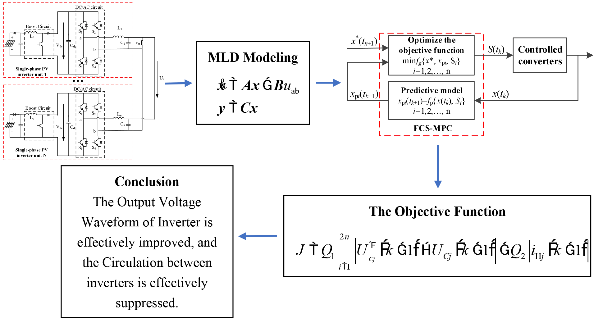
Parallel connection of multiple inverters is an important means to solve the expansion, reserve and protection of distributed power generation, such as photovoltaics. In view of the shortcomings of traditional droop control methods such as weak anti-interference ability, low tracking accuracy of inverter output voltage and serious circulation phenomenon, a finite control set model predictive control (FCS-MPC) strategy of microgrid multi-inverter parallel system based on Mixed Logical Dynamical (MLD) modeling is proposed. Firstly, the MLD modeling method is introduced logical variables, combining discrete events and continuous events to form an overall differential equation, which makes the modeling more accurate. Then a predictive controller is designed based on the model, and constraints are added to the objective function, which can not only solve the real-time changes of the control system by online optimization, but also effectively obtain a higher tracking accuracy of the inverter output voltage and lower total harmonic distortion rate (Total Harmonics Distortion, THD); and suppress the circulating current between the inverters, to obtain a good dynamic response. Finally, the simulation is carried out on MATLAB/Simulink to verify the correctness of the model and the rationality of the proposed strategy. This paper aims to provide guidance for the design and optimal control of multi-inverter parallel systems.Graphic Abstract
Keywords
In recent years, with the continuous progress and development of modern society, the demand for energy is constantly increasing, but it has also brought about a large consumption of traditional energy such as coal and oil, resulting in the gradual exhaustion of fossil energy. In addition, the harmful gases produced by traditional fossil fuel combustion will not only seriously pollute our living environment and cause great harm to human health, but also run counter to the sustainable development strategy implemented by my country [1]. Due to certain current situations, most of the power supply systems in our country are limited by their own problems and gradually cannot meet the increasing functional requirements. In order to maintain sustainable high-quality development in our country and solve the problems of energy shortage and environmental pollution, distributed power generation of new energy represented by wind energy and photovoltaics has attracted more and more attention from all walks of life around the world. Wind power and solar energy are not only a renewable energy sources, but also do not pollute the atmosphere air in use, which makes they are widely promoted [2]. Photovoltaic power generation is one of the main forms of solar energy development and utilization. At the same time, our country has unique advantages in developing the solar energy industry. Therefore, distributed generation (DG) has become a new form of power supply. It has the advantages of cleanliness, high efficiency and flexible installation location. Compared with the traditional large power grid, its advantages are more obvious. However, the distributed power generation has its own limitations, such as high maintenance cost, low energy density, complex control, and unstable power generation etc.
With the development of microgrid, more and more non-linear power electronic devices such as inverters have begun to be integrated into the grid. However, due to the addition of non-linear devices, and the different circuit parameters in the system, the output voltage of the system is distorted. A large circulation is generated between the inverters. In view of these problems in the multi-inverter parallel system, the realization of renewable energy can achieve high-quality grid-connected operation. Therefore, it is necessary to study the control strategy of its photovoltaic inverter parallel system [3].
The main difficulty in the parallel connection of multiple inverters lies in the hybrid nature of their models. At present, the period average method is generally used for inverter modeling, that is, the system state is averaged within a sampling period [4,5]. However, the averaging method cannot accurately obtain the change law of the inverter switch, and the model accuracy is not high, which affects the performance of the controller based on the model design. The mixed logical dynamical (MLD) modeling combines discrete and continuous events together to form a whole differential equation for processing. The discrete quantity is introduced into the expression in the form of logical variable, and this modeling method can more accurately describe the hybrid system where both linear and nonlinear exist at the same time. References [6–8] proposed to establish an MLD model for the hybrid characteristics of the inverter circuit, and carried out simulation verification to obtain a good control effect.
There are various control methods for parallel inverters. At this stage, droop control is often used to control the parallel operation system of inverters. The droop control method is a key technology of parallel control, and the reasonable design of its droop coefficient directly affects the current sharing effect and dynamic response of the inverter in parallel [9]. Although the traditional droop control reduces the dependence on communication reliability, the stability of the system is poor. By introducing virtual impedance, the output impedance of inverter system is adjustable inductance, which reduces the power coupling caused by line resistance, improves the output voltage quality of each inverter and the system stability [10]. But the transient response speed is slow. The improvement can effectively improve the stability and instantaneous response speed. Reference [11] proposed a novel strategy of resonance suppression based on notch filter adding virtual equivalent admittance to the common coupling point. Due to the existence of equivalent impedance in the weak grid environment, the coupling degree between inverters is enhanced when multiple inverters are running in parallel, resulting in resonance, so the whole system is difficult to work in a stable state. Although this strategy improves the stability, the dynamic response is poor. Reference [12] has proposed the research of stable operation control of microgrid parallel multi-inverter considering circulating current suppression. The improved droop control method can control the system to reduce the circulating current value of the system and control the micro-grid parallel multi-inverter to run stably. But there are some limitations. For example, the stable operation of micro-grid parallel multi-inverter is controlled only from the output active power and reactive power of micro-grid parallel multi-inverter. Reference [13] has proposed a new improved droop control strategy, which improves the performance of multi-inverter parallel operation and achieves the high-precision current sharing control of the inverters, so the stability of the microgrid is improved. However, the control effect for multiple targets is not ideal. A variety of instantaneous current sharing control methods have been proposed, such as master-slave current sharing control method [14], circulating chain current sharing control method [15] and so on. However, these methods require a lot of information exchange in the process of system operation, so they are easily disturbed and are not suitable for long-distance control.
Model Predictive Control (MPC) can fully consider the constraints and nonlinear factors of the control object, and simultaneously achieve multiple control objectives by minimizing the value of the objective function, so it is suitable for the control of multi-inverter parallel systems. Compared with the traditional control using PWM technology, MPC can calculate the optimal switching state through the objective function, and control the inverter. The control principle is simple and easy to implement. So it is a very popular control method at present. However, in practical applications, the mixed integer quadratic programming (MIQP) problem will arise when MPC is applied to power electronic circuits [16–18], which will increase the computational complexity and cost of the system. Reference [19] has studied the method of using the optimal switching sequence to fix the switching frequency of FCS-MPC to facilitate filtering out harmonics. Moreover, FCS-MPC utilizes the discrete properties to reduce computing and processing time. It can effectively avoid complex MIQP problems.
The control effect of the above control strategy for multi-objectives is still not ideal. The advantages and limitations of these control strategies are analyzed. In this paper, a multi-inverter parallel FCS-MPC strategy based on MLD modeling is proposed for multi-inverter parallel system in isolated island operation. Firstly, MLD is used to establish the model, FCS-MPC is added to the optimal control process of multi-inverter parallel system, the reference output voltage and the prediction model of micro-grid parallel multi-inverter considering circulating current are established. Secondly, the objective function is established. And then the circulating current is added as a constraint in the objective function value, which can not only solve the real-time change of control system online optimization. But also effectively restrain circulating current, reduce harmonics, improve prediction accuracy, improve output voltage quality and have a good dynamic response. Finally, the simulation on MATLAB/Simulink verifies the correctness of the model and the rationality of the proposed strategy. The purpose of this paper is to provide guidance for the design and optimal control of multi-inverter parallel system.
2 The Multi-Inverter Parallel System
The multi-inverter parallel system cannot only break through geographical restrictions, and connect different distributed power sources far apart in parallel to improve the power generation capacity, but also form a parallel redundant system to improve the operational reliability of the power generation system. The topology of the multi-inverter parallel system is shown in Fig. 1.
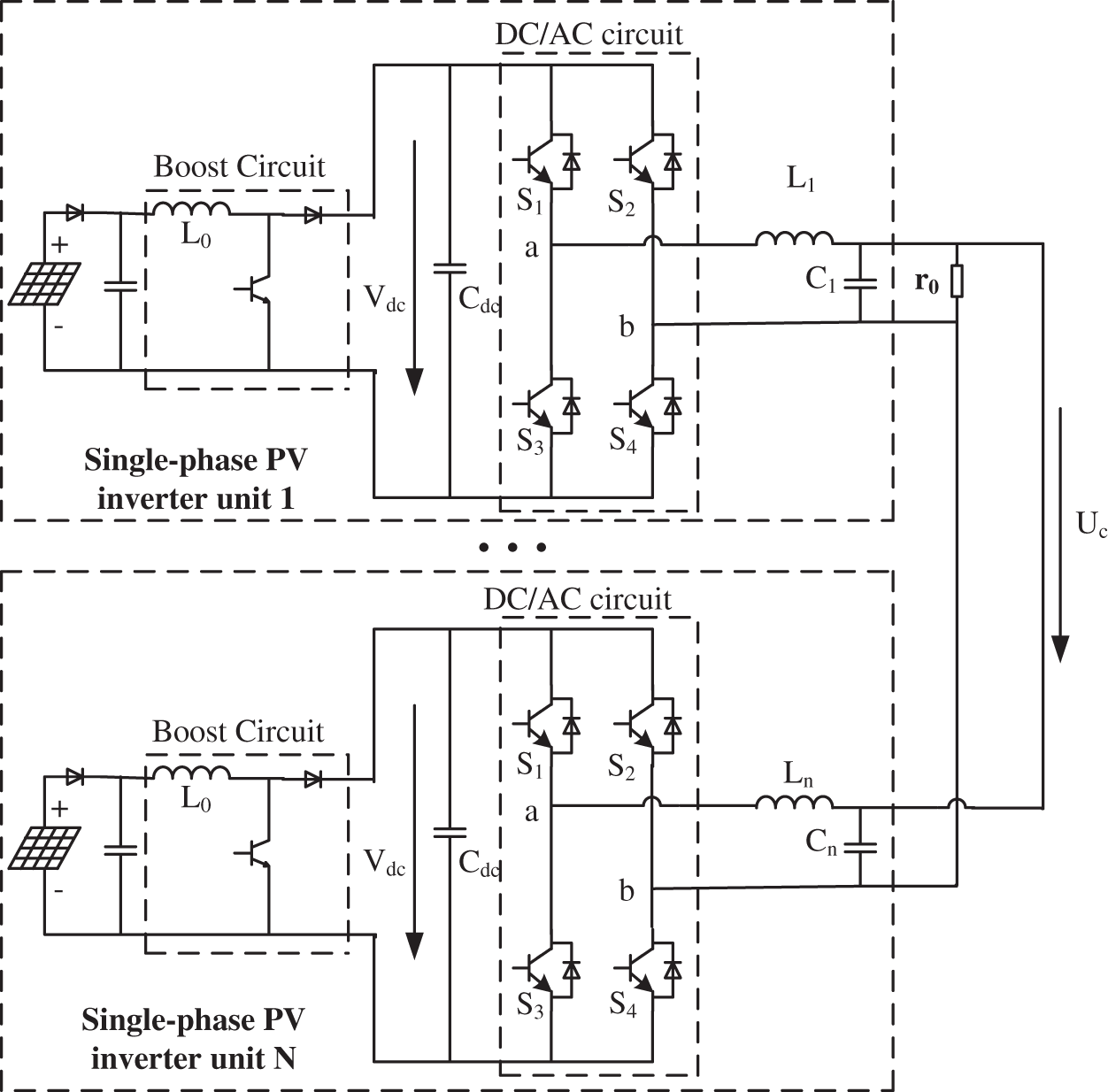
Figure 1: The structure of parallel inverting system
The circuit mainly includes four parts: photovoltaic array, DC/DC circuit, DC/AC circuit, and LC filter circuit. In the figure,
The MLD model needs to introduce logical variables to represent the logical relationships in the system, express the logical relationships and constraints in the system in the form of inequalities, and add them to the system dynamic difference equation to represent various types of hybrid systems. As shown in Eq. (1):
where, x(t) represents the system state variable; u(t) represents the input control variable; y(t) represents the output variable; δ(t) represents the auxiliary logic variable; z(t) represents the auxiliary continuous variable; A, B, C, D and E are constant coefficient matrices.
The core of the MLD model is to analyze the system in a single model, and summarize the physical conditions and related algebras in the state space of all regions in the system into the same model for state analysis. By introducing appropriate auxiliary variables, multiple variables of the system can be controlled and system constraints can be optimized.
The main ideas and methods of establishing the hybrid logic dynamic model of the hybrid system are as follows: Firstly, the system circuit topology is analyzed in different operating states of the system, and then appropriate auxiliary logic variables are selected to describe the different operating states in the system. Finally, the logical relationships and system constraints in the system circuit are all integrated together to form an overall function expression. In other words, Eq. (1) is not just the description of the continuous system model, in which the nonlinear part in the hybrid system is described by logical variables (binary values). Therefore, the mathematical model established by Eq. (1) is a description of the hybrid system.
The circuit topology of the single-phase photovoltaic inverter system designed in this paper is a non-isolated two-stage topology. After decoupling the front and rear stages, the MPPT control voltage is used to keep the voltage stable. There has been a lot of research on this, and it will not be described here. Therefore, in the inverter control research, to make the research more targeted, the photovoltaic array and DC/DC circuit in the circuit are equivalent to a stable DC voltage source. The simplified model is shown in Fig. 2.
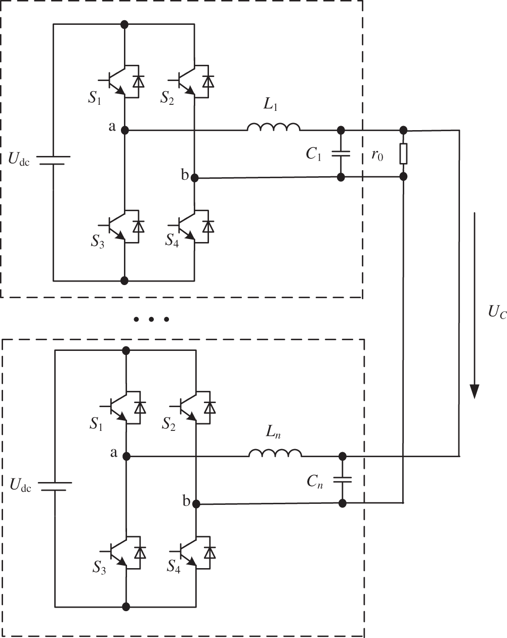
Figure 2: The simplified model of single-phase photovoltaic inverter parallel system
According to the control objective of the system, the system state variable is defined as
The state control signal of the 4 switches of the jth inverter in the voltage-type full-bridge inverter circuit is represented by Sm (m = 1, 2, 3, 4) to represent the switching states of the inverter switches, namely:
Set the first case: S1 and S4 are on, S2 and S3 are off, which is represented by λ = 1, namely:
The second case: S2 and S3 are on, and S1 and S4 are off, which is represented by λ = 0, namely:
Introducing the logic variable δ, is to describe the direction of current ia. Setting the positive direction of current ia is shown in Fig. 1, and it is positive when flowing from the left side of the inductor to the right side. When iL> 0, it is represented by δ = 1, that is:
On the contrary, where iL< 0, it is represented by δ = 0, namely:
Therefore, according to the circuit topology, the logical relationship between the voltage uab and the inverter switch is obtained:
According to the HYSDEL language, the corresponding MLD model difference equation is obtained by combining the logical relationship and the mixed characteristics:
where,
The dynamic equation under the logic hybrid dynamic modeling is processed, namely, Euler forward method is used for discrete processing, and a new parameter equation is obtained.
where,
4 The Finite Control Set Model Predicts the Control Strategy
FCS-MPC controls the system according to a limited combination of switch states. By comparing the outputs of different switching states, the optimal switching state combination which minimizes the objective function is selected as the best control scheme to control the inverter, so pulse width modulation is not needed and the response speed is faster. In addition, FCS-MPC is also suitable for multi-objective control system and can be used for switching frequency control. Constraints are added to the objective function to control the controlled variables, such as output voltage, output current, suppression of circulating current and reduction of switching frequency. Therefore, it is very feasible to apply FCS-MPC strategy to single-phase photovoltaic inverter system. In addition, FCS-MPC effectively solves the computational problems of MPC according to the discrete characteristics of the system. Because the number of switching states in single-phase photovoltaic inverter system is certain, the control program only carries out online traversal calculation for these states, and then obtains the best control scheme to control the inverter [20]. The key of FCS-MPC is the discrete mathematical model of the system and the definition of objective function.
Fig. 3 shows the principle of a converter model predictive control system based on a finite control set, where,
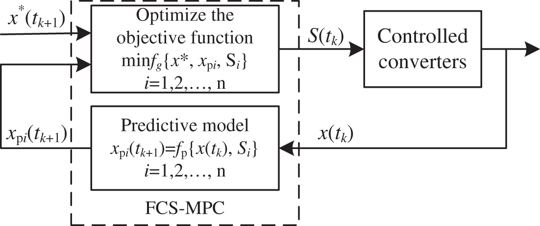
Figure 3: The control block diagram of FCS-MPC
It can be seen from the above control flow that in the FCS-MPC algorithm, the optimization process for the switch function combination is the error comparison process between the predicted value of the controlled variable and the reference value in the objective function. Fig. 4 assume that the converter has only three different switching state combinations (S1, S2 and S3), and the reference value is unchanged, where,

Figure 4: The operating principle of FCS-MPC
In FCS-MPC control, the system prediction model needs to be established according to the controlled quantities in the system, such as voltage, current and so on. In this paper, the MLD method is used for modeling, which can integrate both the linear part and the nonlinear part of the controlled system into a function. At the same time, the objective function is established according to the control objectives and constraints of the system.
The FCS-MPC design generally includes the following three links:
(1) Establish a system prediction model according to the controlled object, and perform discretization processing, to predict the next moment state through the current state. And determine the number of possible switch state combinations in the prediction model.
(2) Establish the objective function according to the controlled quantities and constraints of the system.
(3) Online traversal calculation, namely rolling optimization, obtains the switch function combination that minimizes the objective function value and uses it for the next moment of the inverter.
4.3 Prediction Model of Reference Output Voltage
According to the MPC, the actual output of the system should track the reference output as much as possible. The higher the tracking accuracy is, the better the control effect is. According to the linear Lagrange extrapolation formula, the state of the reference voltage at k+1 is estimated [21], namely:
4.4 Prediction Model of Circulating Current between Inverters
The parallel system model studied in this paper is shown in Fig. 1. In this circuit, the impedance mainly includes line impedance, inverter equivalent impedance and load impedance. The line impedance is much larger than the inverter impedance, so the inverter impedance is ignored when analyzing the circuit. The line impedance consists of resistance
From the circuit topology shown in Fig. 1, taking two inverters in parallel as an example, it can be concluded that:
Among them,
Discretize the differential equation above, and substitute
After further sorting out and changes, we can get:
At the same time, from
After further sorting out it, we can get:
Substitute Eq. (13) into Eq. (15) to predict the inverter output current i1 at time k+1. Similarly, the inverter output current i2 at time k+1 can be obtained, which represents the system output voltage at time k+1, which can be obtained from the prediction model.
The circulating current expression of the inverter parallel system is defined as:
Therefore, the predicted value of the circulation is solved by the following formula:
From Eqs. (13), (15) and (17), it can be known that the circulating current of the inverter parallel system is mainly related to the voltage difference and equivalent output impedance of each inverter output. In this paper, the circulating current is analyzed only when the equivalent output impedance is different.
4.5 Selection of Objective Function
MPC is to predict the state variable of the next moment through the state variable and switch state of the current moment. By sampling the state variable and switch state at the current moment, after obtaining the estimated value of the state variable at the next moment, the optimization objective function is set, and the selected objective function is:
where,
4.6 System Structure of Control Strategy
The FCS-MPC strategy block diagram is shown in Fig. 5, which is applied to the circuit system of two inverters in parallel. The specific process is as follows: firstly, sampling is performed by the sampling unit to obtain the current state variable parameters of the system. Then, the predicted voltage at time k+1 is calculated through the prediction module, and the reference voltage at time k+1 can be obtained through the reference voltage prediction module. At the same time, according to the circulating current analysis, the circulating current between the inverters at time k+1 is predicted. Finally, all of them are sent to the target function module. The objective function module obtains the optimal control scheme through online traversal calculation to control the inverter.

Figure 5: Block diagram of FCS-MPC
According to the diagram of the strategy block in the Fig. 5, the control flow is designed, as shown in Fig. 6. Firstly, the system parameters are sampled, and the objective function is defined, and the initial value is assigned according to Eq. (18). Then the output voltage, reference voltage and circulation between inverters are predicted and estimated, which are transmitted to the objective function for online calculation, and then the switching state combination that minimizes the objective function value is selected for the next time control of the system.

Figure 6: Flow chart of control
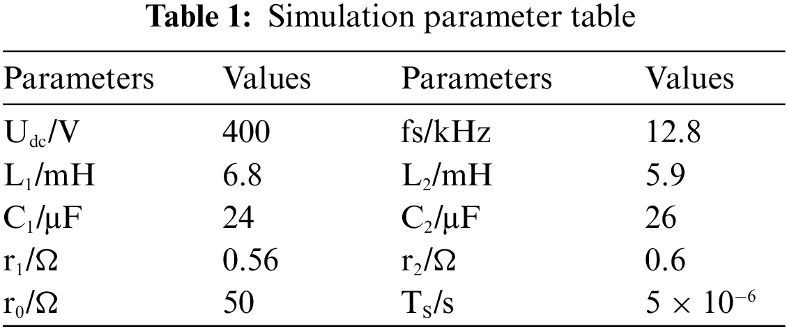
According to the strategy proposed in this chapter, the parallel system of two inverters is designed and simulated by using MATLAB/Simulink software. The simulation parameters are shown in Table 1.
According to the trial-and-error method, the predictive control weight coefficients in the simulation are respectively taken as

Figure 7: Output voltage tracking effect of finite control set model predictive control based on MLD model

Figure 8: Output voltage tracking effect based on traditional virtual resistance droop control method
The Fig. 7 shows the tracking effect of the output voltage of the finite control set model predictive control based on MLD modeling, while the Fig. 8 shows the tracking effect of the system output voltage based on the traditional virtual resistance sag control method. By comparing the simulation results, it can be concluded that the output voltage of the system controlled by FCS-MPC strategy based on MLD model has a better output waveform and better dynamic performance. At the same time, the output voltage of the system can better track the reference voltage and have better tracking accuracy.
The Fig. 9 shows the analysis of the inverter output voltage, inter-inverter circulating current waveform and output voltage harmonic based on the traditional virtual resistance sag control method. Fig. 10 shows inverter output voltage, inter-inverter circulating current waveform and output voltage harmonic analysis under the finite control set model predictive control based on MLD modeling. Compared with the traditional virtual resistance control strategy, the proposed strategy in this paper can effectively improve the output voltage waveform of the inverter, and reduce the THD value of the system output voltage from 8.08% to 3.90%, improve the quality of the system output voltage, and more effectively suppress the circulating current between inverters.

Figure 9: Based on traditional virtual resistance droop control: (a) Output voltage waveform; (b) Circulation waveforms; (c) Output voltage harmonic analysis diagram
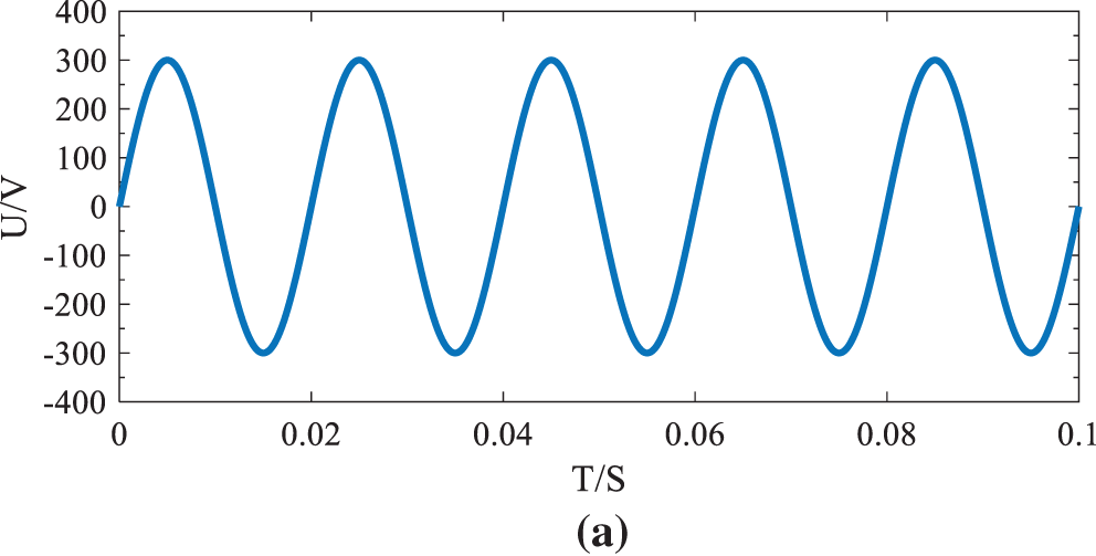
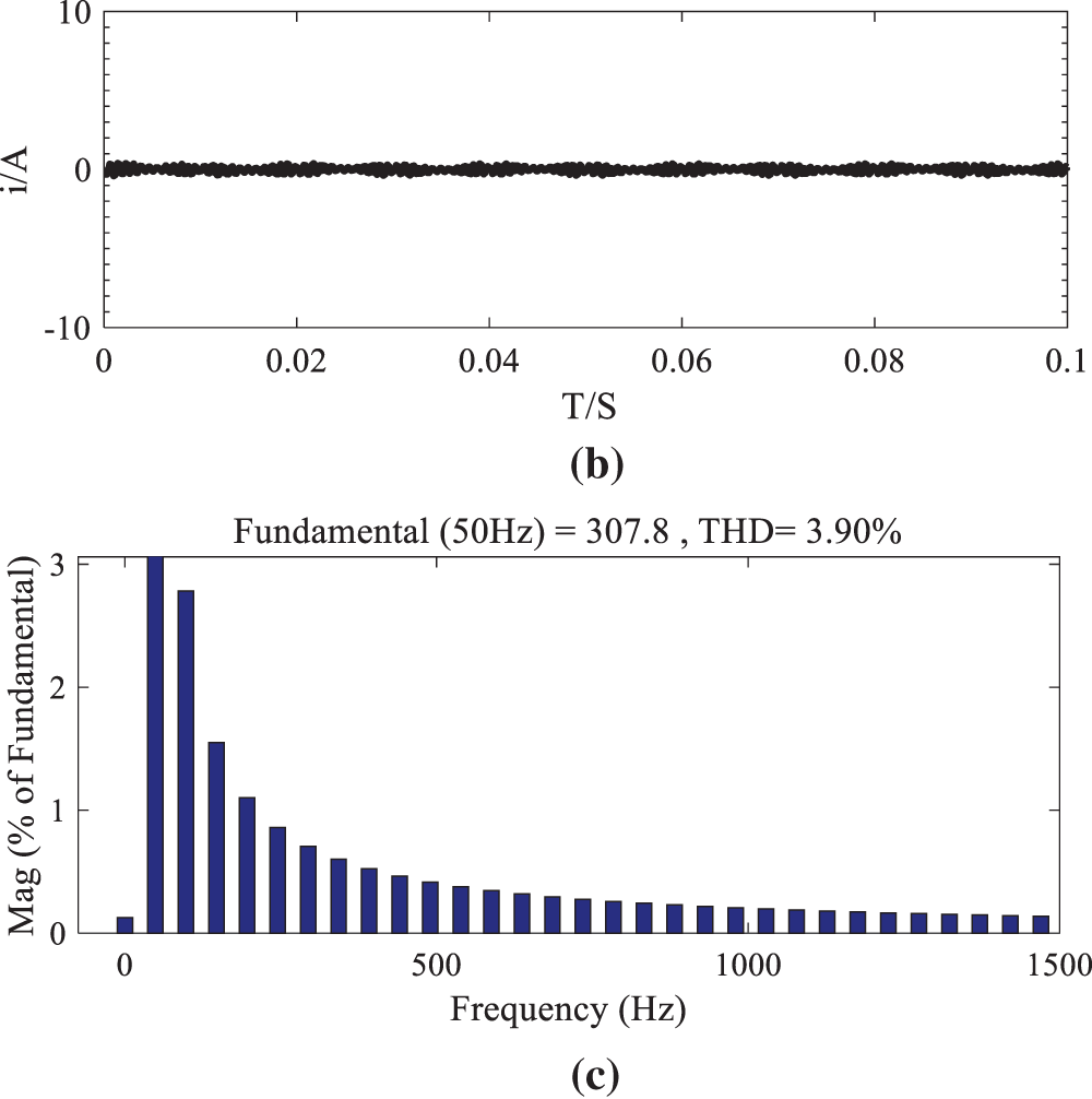
Figure 10: Predictive control of finite control set model based on MLD modeling: (a) Output voltage waveform; (b) Circulation waveforms; (c) Output voltage harmonic analysis diagram
When t = 0.02 s, the load is increased from 50 to 100 Ω. Fig. 11 shows the output voltage at this time. Simulation shows that the output voltage remains stable. Fig. 12 shows the output current at this time. Simulation shows that the load current can quickly reach a new steady state in a short time. It can be seen that the system controlled by the FCS-MPC policy based on MLD model has a good dynamic response.

Figure 11: Output voltage waveform when load suddenly changes

Figure 12: Output current waveform when the load suddenly changes
In this paper, for the micro-grid multi-inverter parallel system, the modeling and control strategy design of the photovoltaic micro-grid multi-inverter parallel configuration are carried. Firstly, the multi-inverter parallel system is analyzed, and the dynamic model of MLD is established. Then the circulating current of the inverter parallel system is analyzed and the objective function is established for FCS-MPC. Finally, the simulation results show that the FCS-MPC strategy based on MLD model can obtain higher tracking accuracy of system output voltage, effectively improve the output voltage waveform of inverter, improve the power quality of output voltage, effectively suppress the circulating current between inverters, and have a good dynamic response. The theory is supported by simulation experiments, and it is shown that this method has certain reference value in the research of stable operation control of micro-grid parallel multi-inverter.
Acknowledgement: Acknowledgement and reference heading should be left justified, bold, with the first letter capitalized but have no numbers. Text below continues as normal.
Funding Statement: This paper is supported by the Major Science and Technology Projects of Gansu Province (Grant No. 20ZD7GF011) and Gansu Province Higher Education Industry Support Plan Project: Research on the Collaborative Operation of Solar Thermal Storage+Wind-Solar Hybrid Power Generation——Based on “Integrated Energy Demonstration of Wind-Solar Energy Storage in Gansu Province” (Project No. 2022CYZC-34).
Conflicts of Interest: The authors declare that they have no conflicts of interest to report regarding the present study.
References
1. Ye, J. (2017). Research on resonance suppression technology of grid-connected inverter (MA. Thesis). Huazhong University of Science and Technology, China. [Google Scholar]
2. Ma, S. H., Zhao, Y. W., Wang, S. C., Kong, L., Li, A. D. et al. (2006). Strategic position and future development direction of photovoltaic power generation in China's power energy structure. Solar Energy, 4(16), 10–16. [Google Scholar]
3. Teng, Q. F., Zuo, J., Pan, H., Xu, R. Q. (2020). Robust voltage control for inverter system using time-varying gain ESO-based adaptive super-twisting algorithm. Control Theory & Applications, 37(9), 1880–1894. [Google Scholar]
4. Wang, H. Y., Lv, G. Q., Zhao, Z. X. (2020). Modeling and analysis of fractional order inverter based on state-space average method. Electrotechnical Application, 39(1), 37–42. [Google Scholar]
5. Wang, J. Y., Ma, C. Y., Li, M., Zhao, C. (2018). Modeling and simulation of single-phase power factor correction based on generalized state space averaging method. Science Technology and Engineering, 18(20), 233–239. [Google Scholar]
6. Li, N., Li, Y. H., Zhu, X. H., Lei, H. L., Yu, J. (2013). Fault diagnosis for new inverter circuits based on mixed logic model and incident identification vector. Power System Technology, 37(10), 2808–2813. [Google Scholar]
7. Han, J. D., Qi, R., Zhang, J. Y., Li, X. F., Wang, C. Q. (2018). An improved P-DPC for inverter based on MLD model. Journal of Air Force Engineering University (Natural Science Edition), 19(1), 65–71+78. [Google Scholar]
8. Ge, X. L., Gou, F., Pu, J. K., Wang, Z. Y. (2016). Diagnosis of open circuit faults for traction inverter based on mixed logic dynamic model. Journal of the China Railway Society, 38(8), 35–40. [Google Scholar]
9. Yao, J., Du, H. B., Zhou, T., Tan, Y. (2015). Improved sag control strategy for parallel operation of microgrid inverters. Power Grid Technology, 39(4), 932–938. [Google Scholar]
10. Tu, Q. H., Zhou, Z. G., Cheng, F. H., Li, L. (2022). Research on parallel operation control strategy of multiple inverters based on virtual impedance. Northeast Electric Power Technology, 43(1), 1–4+27. [Google Scholar]
11. Wang, Y., Gao, A. J., Hu, N., Cao, T., Guo, R. et al. (2022). Resonance suppression strategy of multi-grid-connected inverters in parallel operation. China Southern Power Grid Technology, 16(5), 87–96. [Google Scholar]
12. Jiang, F. Y. (2022). Research on stable operation control of micro-grid parallel multi-inverter considering circulating current suppression. Journal of Power Supply, 1–12. [Google Scholar]
13. Zhang, Y., Ma, H., Lei, B., He, X. N. (2009). Parallel dynamic performance analysis of non-interconnected inverter based on droop characteristic control. Proceedings of the CSEE, 29(3), 42–48. [Google Scholar]
14. Ding, Y. (2019). Research on predictive functional PID control of DC/DC converter based on hybrid system (MA. Thesis). Anhui University of Technology, China. [Google Scholar]
15. Chen, Y. K., Wu, Y. E., Wu, T. F., Ku, C. P. (2003). ACSS for paralleled multi-inverter systems with DSP-based robust controls. IEEE Transactions on Aerospace and Electronic Systems, 39(3), 1002–1015. DOI 10.1109/TAES.2003.1238752. [Google Scholar] [CrossRef]
16. Guo, Q. Y., Wu, J. K., Mo, C., Xu, H. H. (2018). A model for multi-objective coordination optimization of voltage and reactive power in distribution networks based on mixed integer second-order cone programming. Proceedings of the CSEE, 38(5), 1385–1396. [Google Scholar]
17. Han, J. N., Qi, R., Lei, X. B. (2017). FCS-MPC for a new inverter. Electric Machines and Control, 21(11), 19–24. [Google Scholar]
18. Zhang, B., Xu, W. Q., Dai, Q. J. (2019). Finite control set model predictive control for PMSM systems driven by three-phase eight-switch fault-tolerant inverter. Electric Machines and Control, 23(6), 81–92. [Google Scholar]
19. Liu, Z. J., Liu, J., Li, P. C., Wang, L. (2020). Finite set model predictive control of optical storage microgrid inverter. Motor and Control Applications, 47(12), 81–86. [Google Scholar]
20. Shen, K., Zhang, J., Wang, J. (2012). A multi-step predictive model predictive control algorithm for converters with limited control sets. Proceedings of the CSEE, 32(33), 37–44. [Google Scholar]
21. Li, N., Li, Y. H., Han, J. D., Zhu, X. H. (2014). FCS-MPC strategy for inverters based on MLD model. Power System Technology, 38(2), 375–380. [Google Scholar]
22. Zhou, Z. X. (2020). Research on unified control strategy of T-type three-level grid-connected inverter based on finite set model predictive control (MA. Thesis). Lanzhou Jiaotong University, China. [Google Scholar]
Cite This Article
 Copyright © 2023 The Author(s). Published by Tech Science Press.
This work is licensed under a Creative Commons Attribution 4.0 International License , which permits unrestricted use, distribution, and reproduction in any medium, provided the original work is properly cited.
 Downloads
 Citation Tools