
 Submit a Paper
 Propose a Special lssue
 Open Access
ARTICLE

Stability Analysis and Control of DC Distribution System with Electric Vehicles
1 State Grid Shandong Electric Power Company Economic and Technological Research Institute, Jinan, China
2 State Grid Shandong Electric Power Company Limited, Jinan, China
3 State Nuclear Electric Power Planning Design & Research Institute Company Limited, Beijing, China
* Corresponding Author: Xiaoning Ge. Email:
Energy Engineering 2023, 120(3), 633-647. https://doi.org/10.32604/ee.2022.024081
Received 23 May 2022; Accepted 10 August 2022; Issue published 03 January 2023
 View Full Text
 Download PDF
Abstract
The DC distribution network system equipped with a large number of power electronic equipment exhibits weak damping characteristics and is prone to low-frequency and high-frequency unstable oscillations. The current interpretation of the oscillation mechanism has not been unified. Firstly, this paper established the complete state-space model of the distribution system consisting of a large number of electric vehicles, characteristic equation of the distribution network system is derived by establishing a state-space model, and simplified reduced-order equations describing the low-frequency oscillation and the high-frequency oscillation are obtained. Secondly, based on eigenvalue analysis, the oscillation modes and the influence of the key system parameters on the oscillation mode are studied. Besides, impacts of key factors, such as distribution network connection topology and number of dynamic loads, have been discussed to suppress oscillatory instability caused by inappropriate design or dynamic interactions. Finally, using the DC distribution example system, through model calculation and time-domain simulation analysis, the correctness of the aforementioned analysis is verified.Keywords
The medium/low voltage flexible DC power distribution system can flexibly accommodate new DC loads such as Electric Vehicles (EVs) and data centers [1], and efficiently accommodate grid-connected new energy. Due to the lack of strong inertial components and the high proportion of power electronic equipment access, compared with the AC power distribution system, the DC power distribution system has the characteristics of weaker damping and lower inertia, so its stability problem is more prominent [2].
In DC distribution network system, the connection between AC and DC systems is realized through the Voltage Source Converter (VSC): in the grid-connected operation state, the DC voltage control of AC/DC converter is adopted, while in standalone mode, VSC is out of operation, and the DC bus voltage is coordinated and controlled by the DC bus voltage control unit [3] of droop control. The main factors affecting the stability of the distribution system include: (a) source-side control dynamics and interaction between multiple sources [4]; (b) dynamic characteristics of loads [5] and interaction between multiple loads [6]; and (c) source/net/load interactions.
Aiming at the impact of source-side dynamic components on stability, reference [7] explored low-frequency oscillation of the DC system caused by the AC/DC converter, and found that the constant voltage control loop and DC capacitors have a significant impact on the low-frequency oscillation, while the simplification of loads constrained the medium/high frequency stability analysis [8]. For impacts of dynamic loads: negative resistance of CPL has been well researched [5], and interactions among loads have been investigated from the point of view of the modal interaction [9] and aggregated situation [6]. However, current studies tended to ignore dynamics of sources when focused on load interactions [6].
To determine whether DC distribution system is stable or not, reference [10] used Nyquist criterion to analyze the influence of DC line parameters, AC interconnection grid strength and other factors on system stability. A unified mathematical model under the distributed control strategy of DC system is established in reference [11], and a method for determining stability of DC system when the load changes is proposed. Yang et al. [12] studied low frequency oscillation caused by photovoltaic access to flexible DC power distribution system, analyzes the influence of photovoltaic operating point, control parameters and network parameters on oscillation, and points out that the increase of DC network impedance is beneficial to the stability of photovoltaic grid-connected system. Guo et al. [13] studied high frequency oscillation and instability problems in DC system and pointed out the low damping LC loop of converter interacts with the equivalent output impedance of the DC bus voltage control unit, which leads to high frequency oscillation and instability of the DC system. Zhang et al. [14] proposed a stability analysis method for AC-DC hybrid distribution system based on impedance matching, and conducted stability analysis for multi-terminal flexible interconnection devices using two modes of master-slave and droop control.
For stability of DC distribution network system considering the access of EV clusters, the work in this paper is as follows: (a) Firstly, the small disturbance stability model of distribution network system is established, and the broadband oscillation characteristic equation is derived; (b) for the low-frequency oscillation mode, the reduced-order form is derived by means of sensitivity analysis, and key factors are clarified to be the parameters of AC/DC converter; (c) for the high-frequency oscillation problem of distribution network, based on the idea of matrix similarity transformation, the impacts of topology, the number of dynamic loads are identified. Proper design of DC distribution network system could enlarge stable operation domain of system.
2 Model Establishment of DC Distribution System
The typical topology structure of DC distribution network includes radial structure, ring structure and multi-level busbar structure, etc. The DC distribution system in Fig. 1 adopted master-salve control is connected to utility grid via the AC/DC converter.
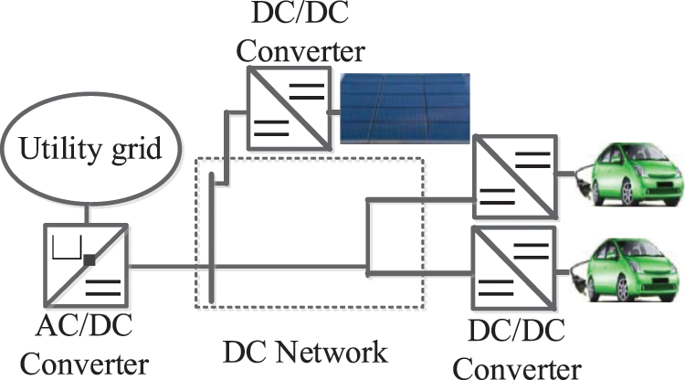
Figure 1: Configuration of the DC distribution system
The AC/DC converter is connected to utility grid through the filter reactance, Xf, as shown in Fig. 2a. Cdc and Udc are the DC bus capacitance and its voltage, respectively. Idc and IDC are currents injected from distribution system and into AC/DC converter, respectively. Id + jIq and Ucd + jUcq are the output AC current and voltage, while Ud + jUq is the terminal AC voltage.
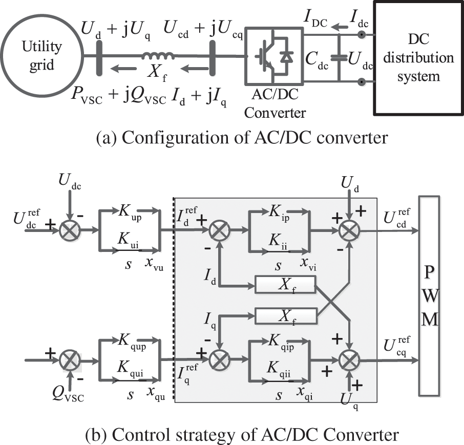
Figure 2: Diagram of AC/DC converter and control strategy
Denote PVSC + jQVSC as output power of AC/DC converter, and PDC = Udc * Idc is the power of DC distribution system. The DC voltage control of AC/DC converter is shown in Fig. 2b. Kup/Kui and Kqup/Kqui are the control parameters of outer loop, and Kip/Kii and Kqip/Kqii are parameters of inner loop. Denote xvu, xvi, xqu, xqi as output terms of integral loops. The linearization state-space model of AC/DC converter can be represented as:
while ∆ XVSC is the vector of state variables, ∆ Uac and ∆ Iac represent the input AC voltage and output currents respectively. Detailed model derivation can be found in reference [8], as presented in Eq. (A1) of Appendix A.
Single dynamic load, EV, could be modeled as a six-order full model constant power load (CPL) or two-order reduced model CPL, based on taking dynamics of DC-DC converters into consideration or not. Considering the CPL oscillation mode associated with converter dynamics generally has good damping when classic converter parameters are used, the two-order CPL model [2] as shown in Fig. 3 are used. UdcL and IdcL are the node voltage and injected current, respectively. RdcL and LdcL are the line resistance and inductance of CPL. CFL and UFL are the filter capacitance and its voltage of DC/DC converter, while the load power is PTL = UFL * IF.
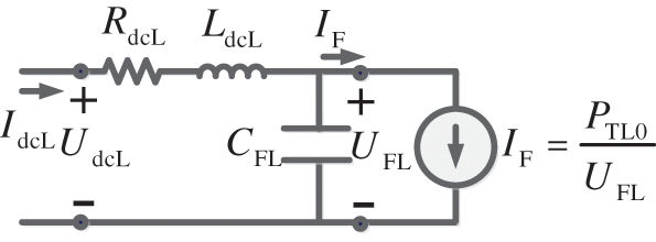
Figure 3: Model of the two-order CPL
The state-space model of the kth CPL can be presented as shown in Eq. (2). ∆ XCPLk is the vector of CPL state variables.
2.3 DC Topology and Load Group Model
Based on the single model of CPL shown above, the model of aggregated loads can be derived. For instance, electrical bus charging station of N CPLs are integrated to DC network via a common coupling point (PCC) whose voltage is UPCC, PCC is connected to DC bus through a common transmission line of resistance R0 and inductance L0. For CPLs connected in parallel, the input voltage is derived as shown in Eq. (3a). For arbitrary topology of CPLs connection, ∆UdcLk is presented in Eq. (3b), while RNkk/LNkk is the total resistance/inductance from kth CPL to PCC, and RNij/LNij is resistance/inductance of the common line of ith and jth load to PCC.
Denote
while
2.4 Interconnection Model of Distribution Network System
Denote Xscr as the reactance of AC line between utility grid and the AC/DC converter, the dynamic model of AC side can be simplified into the form shown in Eq. (5a). The state-space model of utility grid and AC/DC converter is given in Eq. (5b). Thus, closed-loop state-space model of DC distribution system with aggregated CPLs can be derived as shown in Eq. (5c).
Based on Eq. (5), it can be concluded that, the stability of DC distribution system is determined by three parts: (a) the open-loop stability of AC side, AS; (b) stability of aggregated loads, AL; and (c) interaction among load and source subsystem, BS CL/BL CS. Detailed elements of Eq. (5b) are listed in Eq. (A4).
3 Stability Analysis and Enhancement Measures of DC Distribution Network
To describe the stability issue in brief, taking the system in Fig. 4 as an example with CPLs connected in parallel connection.
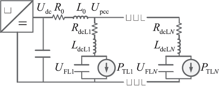
Figure 4: Equivalent circuit of the DC system with EVs
The dynamic equation of DC capacitance voltage is derived in Eq. (6a), while the term ∆xvu and ∆xqu present the impacts of AC/DC control loop on the stability of distribution system. The term Idc0 and ∆Idc represent the influences of stable state power flow and dynamics of loads, respectively. ∆Ud and ∆Uq are the impacts of dynamics of AC utility grid.
AC/DC converter usually takes the d-axis orientation thus Uq0 ≈ 0, and utility grid can be modeled as an infinite bus thus ∆Ud = ∆Uq = 0, dynamic equation in Eq. (6a) can be simplified into the form shown in Eq. (6b), which is the low-frequency reduced-order characteristic equation. Detailed elements of Eq. (6b) are presented in Eq. (A5) of Appendix A.
3.1 Low-Frequency Stability Dominated by AC/DC Converter
Based on the dynamic relationship in Eq. (6b), when the dynamic of DC loads are ignored, ∆Idc = 0, the low-frequency characteristic is simplified into Eq. (7a), and the real part of the corresponding oscillation mode is derived in Eq. (7b).
It can be seen from Eq. (7b) the low-frequency oscillatory mode dominated by AC/DC converter is mainly affected by control parameter Kup, DC capacitance Cdc, power flow of the distribution system Idc0. The damping of low-frequency mode would be improved as Kup increased, be deteriorated when Cdc increased. And the total charging power addition would lead to the deterioration of system stability. To maintain low-frequency stable, the parameter conditions should make the inequality, real (λVSC) < 0, holds. The dynamics of DC current, ∆Idc, is determined by input impedance of CPLs, which are negative among low-frequency ranges, indicating that oscillatory estimation results shown in Eq. (7) are conservative.
3.2 High-Frequency Stability Dominated by Aggregated CPLs
The state-space model of the CPLs in parallel connection at PCC is derived as shown in Eq. (8a). And the voltage, ∆UFLk, is presented in Eq. (8b). Therefore, the state-space model of the aggregated CPLs is described by Eq. (8c).
While,
In order to further clarify the influencing factors of the stability characteristics of the CPL group, it could be assumed that the dynamics of N CPLs are the same. According to the principle of matrix similarity transformation [6], AL in Eq. (4b) can be diagonalized into the form as shown in Eq. (9).
While,
Based on Eq. (9), it can be concluded the dynamic stability of CPL group is mainly affected by:(i) the open-loop stability characteristics of single CPL, ACPL; (ii) the interactions among CPLs, N * AX. The high-frequency dominant oscillation mode, λCPL0, is calculated based on matrix similarity transformation, and high-frequency stability is achieved when parameter conditions makes the inequality, real (λCPL0) < 0, holds. When CPLs dynamic models are not the same, Matrix Perturbation Theory based on state-space model [15] or differences among CPL input impedance based on impedance model [16] could be adopted.
The partial derivatives of the damping, in Eq. (10), of mode of ACPL + N * AX represent the impacts of crucial factors on high-frequency dominant oscillation mode: the number of CPL, N, has a negative influence and the parameter of common line, L0, plays an important role in stability operation.
Tested DC distribution network adopts the configuration shown in Fig. 4 with N0 = 5 CPLs in parallel connection. Typical parameters of distribution system in [17] are used.
4.1 Eigenvalue Analysis of DC Distribution System
Firstly, considering dynamic models of CPLs are the same. based on the state-space matrix A of the interconnected system in Eq. (5c), oscillation mode results of the distribution network system can be obtained, as shown in Table 1. According to the different frequency ranges, it can be roughly divided into two types: high-frequency oscillation modes and medium/low frequency oscillation modes.
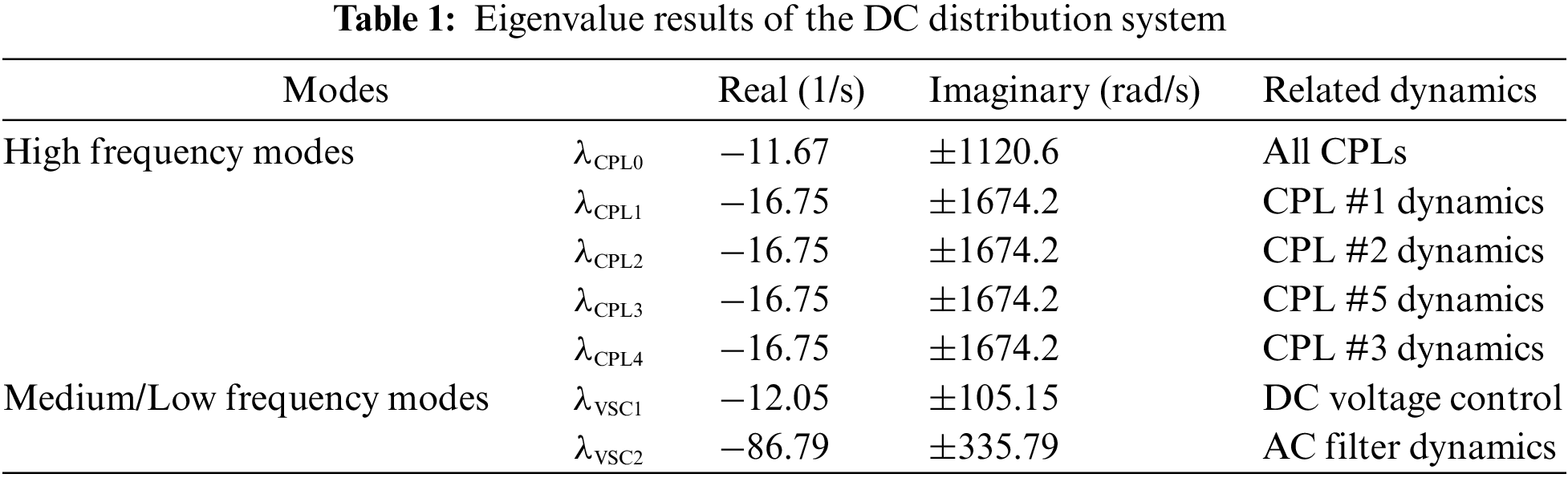
Analysis results of participation factors (PFs) of oscillation modes in Table 1 are shown in Fig. 5. Among them, the high-frequency oscillation modes are more related to load dynamics of CPLs. Mode
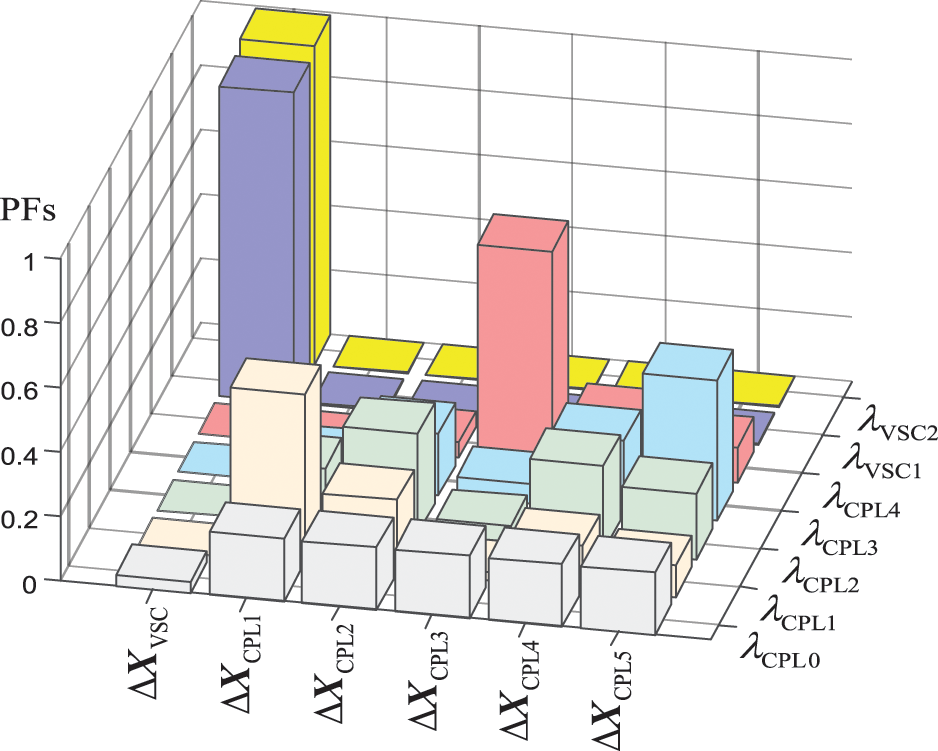
Figure 5: PFs calculation results of oscillation modes
The low-frequency mode
The calculation results in Table 1 show that the small-signal stability of DC distribution network system is mainly determined by DC side load in high frequency range and AC/DC converter station in middle/low frequency range. In the following chapter, the impact of system parameters and control parameters on the oscillation modes of different frequency ranges is explored according to the sensitivity analysis.
4.2 Eigenvalue Sensitivity Analysis of DC Distribution System
The sensitivity calculation results of mode
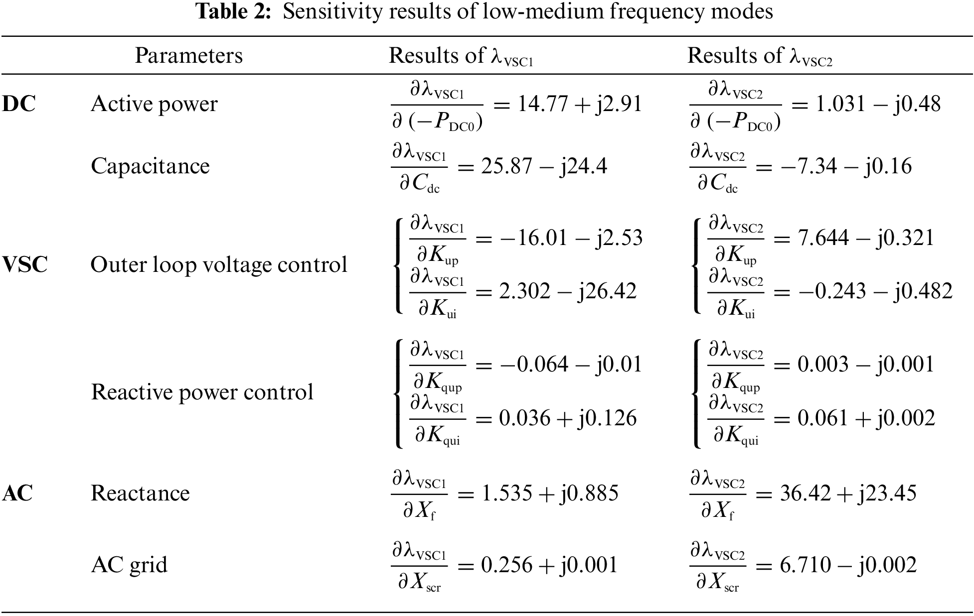
According to the calculation results of the oscillation mode sensitivity, it can be seen the low-frequency oscillation mode
The results from Tables 1 to 2 show that the mode
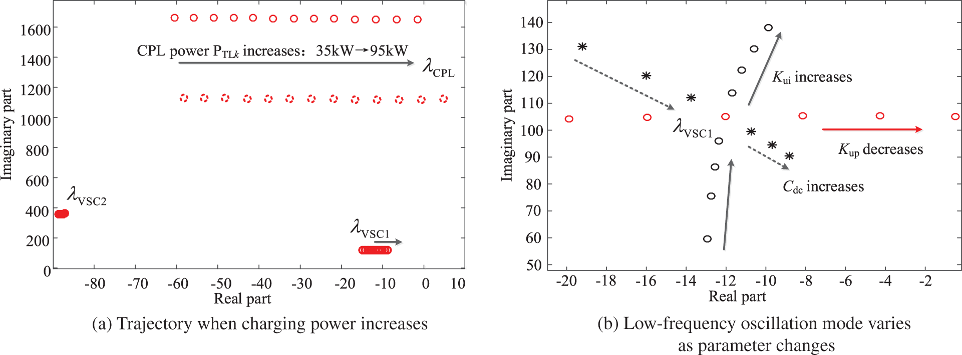
Figure 6: Trajectory of the low-frequency oscillation modes
For the high-frequency oscillation mode,
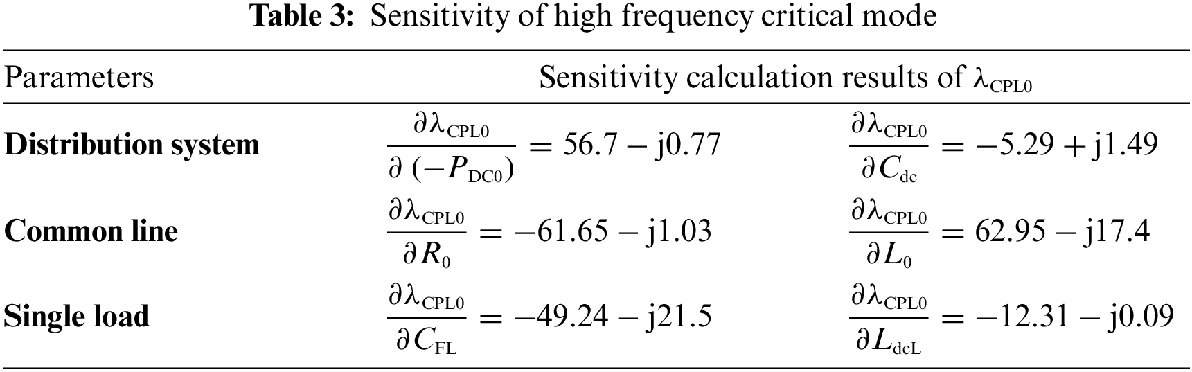
Mode
Taking typical connection topology of charging EVs as an example: the parallel connection, ring-structure connection and series-connection are depicted as shown in Fig. 7a. And the trajectory of mode
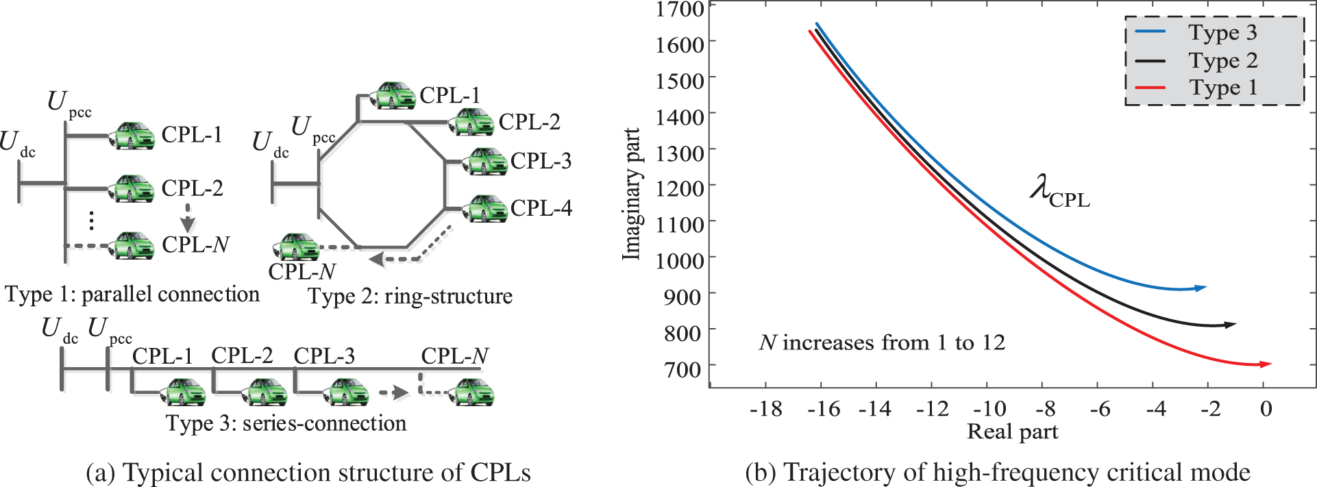
Figure 7: Trajectory of the high-frequency oscillation modes
For the low-frequency range stability: taking the impact of control parameter of voltage control outer loop of the AC/DC converter as examples. The initial number of CPLs is N0 = 5. The charging power of CPL#1 drops by 20% at 1 second, and the simulation results of DC bus voltage and the power of CPL#5 are presented in Figs. 8a and 8b, respectively. Three situations are compared: (i) Kup = 0.5; (ii) Kup = 1.5; (iii) Kup = 2.5. It can be seen that the increasing Kup helps improving the low-frequency dynamic characteristics of DC distribution system.
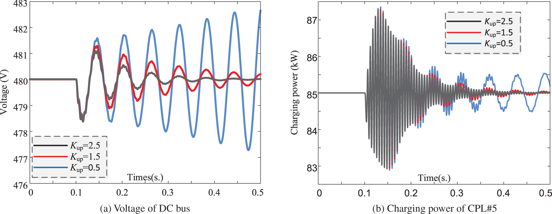
Figure 8: Simulation results of DC system (Low-frequency)
For the high-frequency range stability: taking DC system of topology type 1 for simulation conduction: simulation results in Figs. 9a and 9b are the DC bus voltage and active power of CPL#5, respectively. Two situations are compared: (i) N = 5; (ii) N = 12. Charging power of CPL#1 in test system drops by 20% at 1 s of simulation. It can be seen that DC distribution system turns unstable as number of aggregated CPLs increases, demonstrating the correctness of former analysis. Stability enhancement manner could be adopted based on two aspects: improving the damping of single CPL [5] or decreasing the strength of interactions among CPLs [6]. Detailed description about the effect of stability enhancement is omitted due to the length limitation of this paper. Simulations are conducted based on the full electromagnetic transient model built in MATLAB.
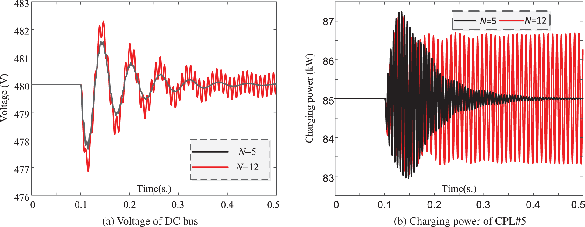
Figure 9: Simulation results of DC system (High-frequency)
5 Conclusion Research Prospect
This paper studies the broadband oscillation characteristics of DC distribution network by establishing the small-signal state-space model of VSC-based DC distribution system with aggregated loads. Main work and conclusions are as follows:
(1) Based on eigenvalue and participation factor analysis, the dominant oscillation mode in the flexible DC distribution network system is identified, and impacts of typical system parameters on dominant oscillation modes are analyzed. It is found that the low frequency oscillation mode of the distribution network is mainly affected by the dynamic effect of the AC/DC converter, and high frequency dominant mode is mainly influenced by interactions of aggregated dynamic loads. Eigenvalue analysis method could provide a clear mechanistic explanation on system oscillation, but its own limitations requires improved analysis method to be adopted in future research work.
(2) The oscillation characteristics of high frequency and low frequency ranges are analyzed, respectively, and reduced order simplified model of oscillation characteristics in different frequency ranges are derived. Influencing factors of oscillation in various frequency ranges of distribution system are analyzed.
(3) In this paper, the CPL model is assumed to be the same, which is only suitable for large-scale scenarios of electric bus charging stations. Future research will focus on extending the research to different application situations of distribution network. The load in this paper only discusses the typical constant power load represented by electric vehicles, and the coexistence of multiple dynamic loads should be considered in the future research. The DC distribution network studied in this paper adopts master-slave control strategy under grid-connected operation state. Future research will explore the stability mechanism analysis and control strategy under off-grid operation state and adopting peer control.
Funding Statement: This work was supported by the State Grid Shandong Electric Power Company Economic and Technical Research Institute Project (Grant No. SGSDJY00GPJS2100135).
Conflicts of Interest: The authors declare that they have no conflicts of interest to report regarding the present study.
References
1. Lee, J. Y., Kim, H. S., Jung, J. H. (2020). Enhanced dual-active-bridge DC-DC converter for balancing bipolar voltage level of DC distribution system. IEEE Transactions on Industrial Electronics, 67(12), 10399–10409. DOI 10.1109/TIE.2019.2959503. [Google Scholar] [CrossRef]
2. Tabari, M., Yazdani, A. (2014). Stability of a DC distribution system for power system integration of plug-in hybrid electric vehicles. IEEE Transactions on Smart Grid, 5(5), 2564–2573. DOI 10.1109/TSG.2014.2331558. [Google Scholar] [CrossRef]
3. Chen, D., Xu, L., Yu, J. (2017). Adaptive DC stabilizer with reduced DC fault current for active distribution power system application. IEEE Transactions on Power Systems, 32(2), 1430–1439. [Google Scholar]
4. Krismanto, A. U., Mithulananthan, N. (2018). Identification of modal interaction and small signal stability in autonomous microgrid operation. IET Generation Transmission & Distribution, 12(1), 247–257. DOI 10.1049/iet-gtd.2017.1219. [Google Scholar] [CrossRef]
5. Xu, Q., Jiang, W., Blaabjerg, F., Zhang, C., Zhang, X. et al. (2020). Backstepping control for large signal stability of high boost ratio interleaved converter interfaced DC microgrids with constant power loads. IEEE Transactions on Power Electronics, 35(5), 5397–5407. DOI 10.1109/TPEL.2019.2943889. [Google Scholar] [CrossRef]
6. Du, W., Zheng, K., Wang, H. F. (2019). Oscillation instability of a DC microgrid caused by aggregation of same constant power loads in parallel connection. IET Generation, Transmission & Distribution, 13(13), 2637–2645. DOI 10.1049/iet-gtd.2018.6940. [Google Scholar] [CrossRef]
7. Amin, M., Molinas, M. (2017). Small-signal stability assessment of power electronics based power systems: A discussion of impedance- and eigenvalue-based methods. IEEE Transactions on Industry Applications, 53(5), 5014–5030. DOI 10.1109/TIA.2017.2712692. [Google Scholar] [CrossRef]
8. Gao, F., Bozhko, S., Costabeber, A., Patel, C., Wheeler, P. et al. (2017). Comparative stability analysis of droop control approaches in voltage-source-converter-based DC microgrids. IEEE Transactions on Power Electronics, 32(3), 2395–2415. DOI 10.1109/TPEL.2016.2567780. [Google Scholar] [CrossRef]
9. Du, W., Zheng, K., Wang, H. F. (2020). Instability of a DC microgrid with constant power loads caused by modal proximity. IET Generation, Transmission & Distribution, 14(5), 774–785. DOI 10.1049/iet-gtd.2019.0696. [Google Scholar] [CrossRef]
10. Zhao, X., Peng, K., Zhang, X., Liu, J., Zhao, Y. et al. (2019). Research on influencing factors and improving methods for DC distribution system stability. The Journal of Engineering, 16(3), 2147–2153. DOI 10.1049/joe.2018.8557. [Google Scholar] [CrossRef]
11. Zhi, N., Zhang, H., Xiao, X., Yang, J. (2016). System-level stability analysis of DC microgrid with distributed control strategy. Proceedings of the CSEE, 36(2), 368–378. [Google Scholar]
12. Yang, X., Sun, Y., Wei, W. (2018). Power oscillation analysis of PV generators connected to DC distribution network. Proceedings of the CSEE, 38(23), 6814–6824. [Google Scholar]
13. Guo, L., Feng, Y., Li, X. (2016). Stability analysisi and research of active damping method for DC microgrids. Proceedings of the CSEE, 36(4), 927–963. [Google Scholar]
14. Zhang, X., Pei, W., Deng, W., Yu, T., Huang, R. (2017). Stability analysis of AC/DC distribution system with constant power loads. Proceedings of the CSEE, 37(19), 5572–5582. [Google Scholar]
15. Dong, W., Xin, H., Wu, D., Huang, L. (2019). Small signal stability analysis of multi-infeed power electronic systems based on grid strength assessment. IEEE Transactions on Power Systems, 34(2), 1393–1403. DOI 10.1109/TPWRS.2018.2875305. [Google Scholar] [CrossRef]
16. Zheng, K., Du, W., Wang, H. F. (2021). DC microgrid stability affected by aggregated constant power loads based on impedance method. Power System Technology, 45(1), 134–148. [Google Scholar]
17. Tabari, M., Yazdani, A. (2015). A mathematical model for stability analysis of a DC distribution system for power system integration of plug-in electric vehicles. IEEE Transactions on Vehicular Technology, 64(5), 1729–1738. DOI 10.1109/TVT.2014.2336854. [Google Scholar] [CrossRef]
Appendix A. Equations
Cite This Article
 Copyright © 2023 The Author(s). Published by Tech Science Press.
This work is licensed under a Creative Commons Attribution 4.0 International License , which permits unrestricted use, distribution, and reproduction in any medium, provided the original work is properly cited.
 Downloads
 Citation Tools