
 Submit a Paper
 Propose a Special lssue
 Open Access
ARTICLE
Control System Design for Low Power Magnetic Bearings in a Flywheel Energy Storage System
1 Department of Mechanical Engineering, Chiang Mai University, Chiang Mai, 50200, Thailand
2 Department of Mechanical Engineering, Shamoon College of Engineering, Be’er Sheva, 84100, Israel
* Corresponding Author: Matthew O. T. Cole. Email:
Energy Engineering 2023, 120(1), 147-161. https://doi.org/10.32604/ee.2022.022821
Received 28 March 2022; Accepted 29 July 2022; Issue published 27 October 2022
 View Full Text
 Download PDF
Abstract
This paper presents a theoretical and experimental study on controller design for the AMBs in a small-scale flywheel energy storage system, where the main goals are to achieve low energy consumption and improved rotordynamic stability. A H-infinity optimal control synthesis procedure is defined for the permanent-magnet-biased AMB-rotor system with 4 degrees of freedom. Through the choice of design weighting functions, notch filter characteristics are incorporated within the controller to reduce AMB current components caused by rotor vibration at the synchronous frequency and higher harmonics. Experimental tests are used to validate the controller design methodology and provide comparative results on performance and efficiency. The results show that the H-infinity controller is able to achieve stable rotor levitation and reduce AMB power consumption by more than 40% (from 4.80 to 2.64 Watts) compared with the conventional PD control method. Additionally, the H-infinity controller can prevent vibrational instability of the rotor nutation mode, which is prone to occur when operating with high rotational speeds.Keywords
Flywheel energy storage systems (FESS) are being increasingly used in applications where high efficiency, long cycle life, wide temperature range and high power density are primary requirements [1]. Examples include regenerative power for machines and vehicles, energy storage and motion control in satellites, uninterruptible power supply for critical systems (UPS), and power grid stabilization [2–4]. In electric vehicles, a FESS can provide short bursts of power when peaks in demand exceeds battery power. Use as backup and bridging power for renewable energy sources can also play an important role in sustainable energy solutions [5,6].
For optimum efficiency, FESS should be designed to operate in a way that minimizes overall power consumption of the flywheel subsystems. To reduce frictional losses, flywheel rotors are sealed in vacuum enclosures and are supported without mechanical contact by active magnetic bearings (AMBs). High rotational speeds from 20,000 to 50,000 RPM are then achievable. Use of AMBs can also reduce wear and maintenance requirements compared with rolling element bearings [7]. This paper describes recent research on creating AMB systems that are compact, highly efficient, and suitable for small-scale FESS, where AMB operating losses make a significant contribution to the overall power consumption of the system.
AMBs incorporate electromagnets that apply time-varying forces to the flywheel rotor to maintain stable positioning and low vibration. To reduce power consumption of AMB operation, permanent magnets (PMs) can be used to generate the static/mean components of the magnetic flux through the AMB poles [8–10]. Note that PMs cannot replace AMBs completely due to the fundamental stability properties of conservative magnetic fields, as well as the lack of damping effects. However, by using PM-biasing, operation with very low RMS currents in the electromagnetic coils is possible [11,12]. Using PMs for bias flux generation also allows more linear characteristics for the force-displacement-current relations to be achieved (compared with approaches based on low or zero bias currents). Consequently, linear control methods can be readily applied for feedback control. Nonetheless, to achieve stable suspension of a rotor over a wide range of rotational speeds, sophisticated control algorithms are required [13]. It is essential that the design of the AMB controller accounts for gyroscopic effects and the influence they have on the vibrational dynamics of the rotor. Previous studies have highlighted the problem of vibrational instability caused by rotor nutation [14–16]. As the rotor nutation frequency increases with rotational speed, this must be accounted for in the design of the feedback control algorithm to avoid destabilization. However, requirements for low power operation, which mandate low-current, low-bandwidth control, can conflict with this aim when using conventional control methods [17].
This paper describes an optimal controller design procedure for the AMBs in a small-scale FESS. The main objectives for the controller design were to achieve rotordynamic stability and acceptable vibration, while minimizing AMB currents at targeted rotational speeds for low power operation. The FESS design is based on a 6 kg rotor, giving potential storage capacity up to 70 Wh. The target for power consumption of the AMBs was less than 3 watts (corresponding to 1.5 Wh total energy consumption for a 30-min discharge cycle). Section 2 of the paper describes the main components of the flywheel system and the experimental setup of the AMB controller. Section 3 defines the system dynamic model based on linearized equations for the rotor and AMB subsystems. Section 4 introduces a basic controller design based on PD (proportional-derivative) feedback of measured rotor displacements. This controller can achieve stable rotor suspension for low rotational speeds but requires high energy consumption and cannot preserve rotordynamic stability at high speeds. Therefore, a model-based design approach based on H-infinity control optimization is introduced. Notch filter characteristics are incorporated within the controller to reduce harmonic components in the AMB currents caused by rotor vibration. Experimental results are presented in Section 5 to validate the controller design methodology and evaluate the achievable levels of vibration and power consumption. Section 6 provides conclusions.
2 Experimental Small-Scale Flywheel Energy Storage System
The experimental FESS prototype used in this study is shown in Fig. 1. The rotor is supported by two homopolar PM-biased radial AMBs, with one permanent magnet thrust bearing for vertical axis support. The magnetic fields produced by the AMB coils superimpose with the fields from the permanent magnets to generate forces in the horizontal plane for controlling motion of the rotor. As the rotor is stabilized passively in the vertical direction, there are four remaining degrees of freedom that must be controlled using the AMBs. Displacement sensors at the upper and lower AMBs measure the motion of the rotor for feedback control purposes. Important flywheel rotor properties are given in Table 1. The tested version of the rotor was designed for operation up to a maximum rotational speed of
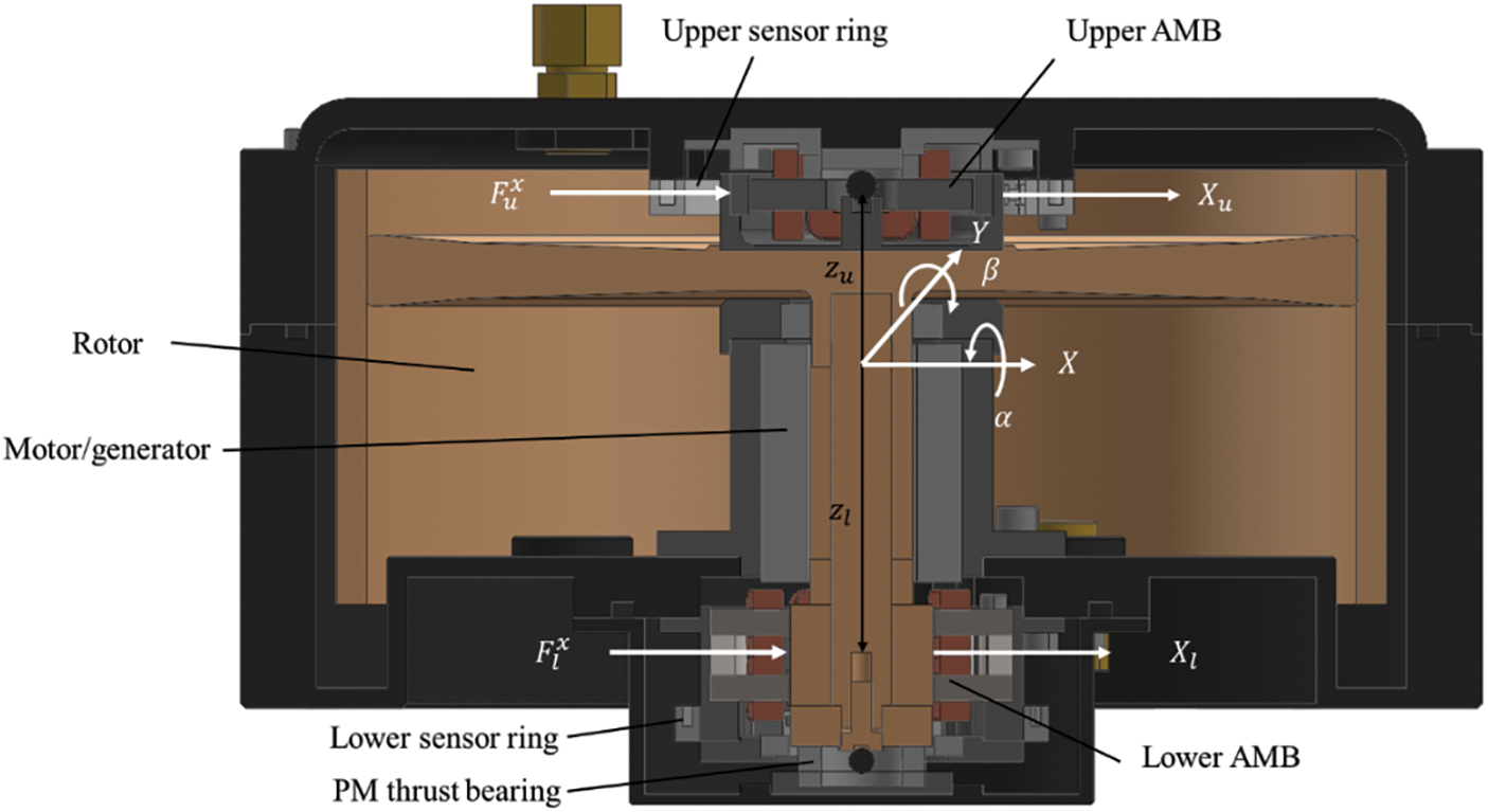
Figure 1: Cross section of FESS system showing main components and motion variables

The experimental setup for testing is shown in Fig. 2. The main purpose of the experiments was to evaluate the system performance in respect of flywheel vibration behavior and AMB current consumption. The electrical connections to the flywheel include the rotor displacement sensors and power connections to the AMB coils and to the motor/generator. The AMBs are powered by small DC servo-drives (Maxon ESCON 24/2). The motor/generator is a brushless PM motor with peak power rating of 1 kW. All subsystems are powered by a single 24 volt supply. Current meters were used to observe the RMS (root-mean-square) current consumption of the AMB and motor drives. The flywheel housing is sealed for primary vacuum conditions to eliminate air resistance. The temperature of the AMB and motor coils is monitored with thermocouples to avoid overheating. The displacement sensors are inductive (eddy current) type and use small coils installed within the rotor housing. The feedback controllers were implemented digitally using PC-based control hardware (United Electronic Industries) with sampling frequency of 5000 Hz.
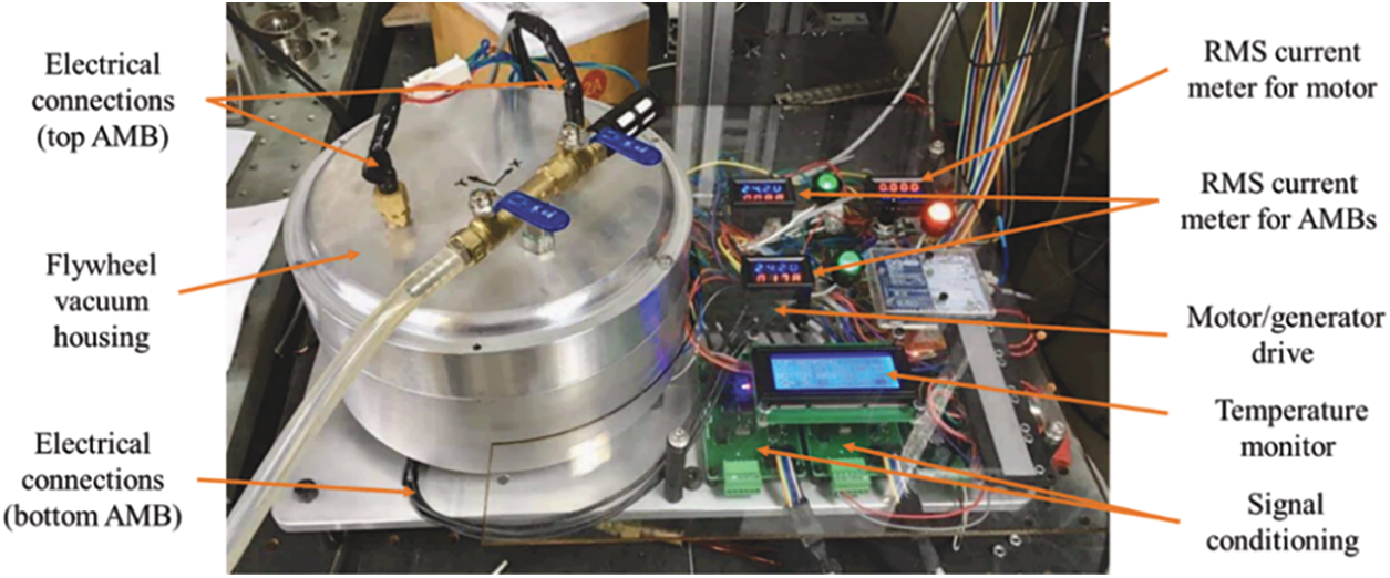
Figure 2: Prototype small-scale flywheel energy storage system: Experimental setup
3 Flywheel Rotor-AMB System Dynamics
To construct the theoretical model describing motion of the flywheel rotor, the coordinate system shown in Fig. 1 is adopted. Defining rotor center-of-mass displacements as
where Ω is the rotational frequency of the rotor. The mass, gyroscopic and force allocation matrices are respectively given by
The forces applied to the rotor by the upper bearing (
where
Using Eq. (3) in Eq. (1) gives
The horizontal displacements of the rotor measured at the sensor locations can be expressed
Hence, from Eqs. (5) and (6), the dynamics of the rotor-AMB system with inputs
Stability of the flywheel dynamics can be assessed by evaluating the poles of
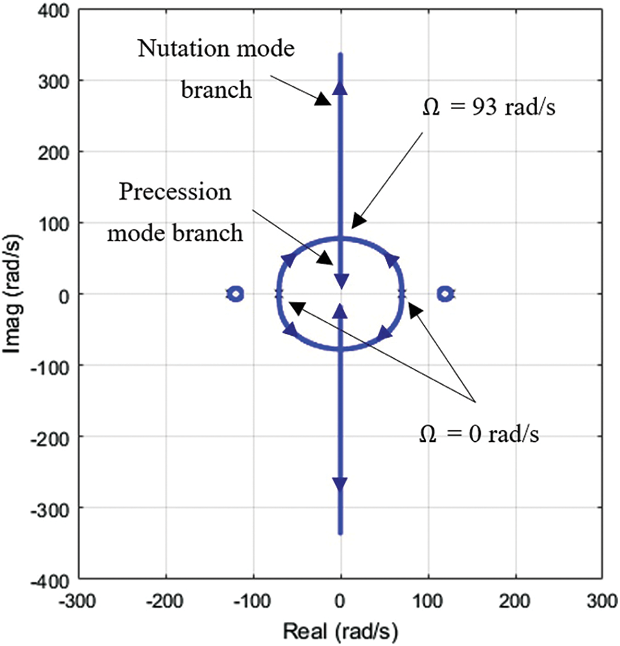
Figure 3: Root locus diagram for the flywheel dynamics with speed range Ω = 0 to 200 rad/s
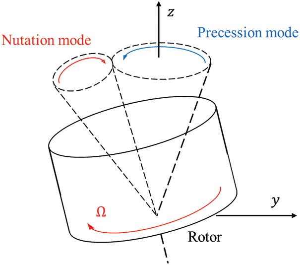
Figure 4: Flywheel motion associated with gyroscopic modes
4.1 Proportional-Derivative Controller
It is clear that an AMB control system must be applied to maintain dynamic stability. In simple terms, the controller must shift all system poles to the left half of the complex plane for all speeds within the operating range. To stabilize the rotor when rotating at low speed, a standard PD feedback controller can be applied. The transfer function matrix for the PD controller (with break frequency
where
The characteristics of the flywheel system with PD control can be evaluated from the closed loop transfer function given by
Fig. 5 shows the trend of changing poles of
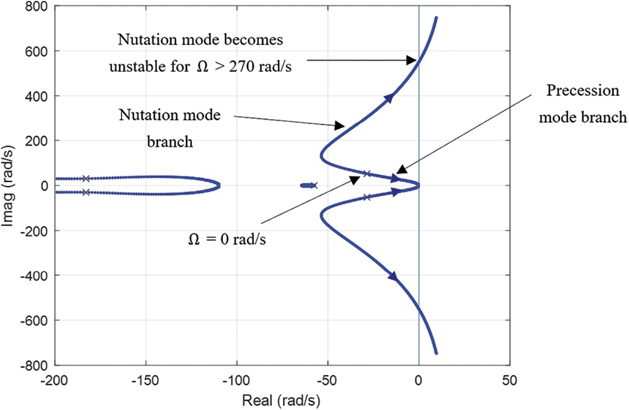
Figure 5: Root locus of rotor-AMB system with PD controller for speeds Ω = 0 to 400 rad/s

Ideally, the AMB controller should operate with the smallest possible coil currents, as this will reduce power consumption and heat generation within the AMB coils and drives. Radial forces associated with rotation of the flywheel excite vibration of the rotor, causing non-zero displacement measurements. These are acted on by the feedback controller, resulting in non-zero current values. Although the mean current components can be easily set to zero by using integral feedback control (or offset adjustment), other excitation components are more difficult to eliminate. Initial experiments indicated that the two main excitation frequencies are one-times and three-times the rotational frequency, as seen in Fig. 6. The
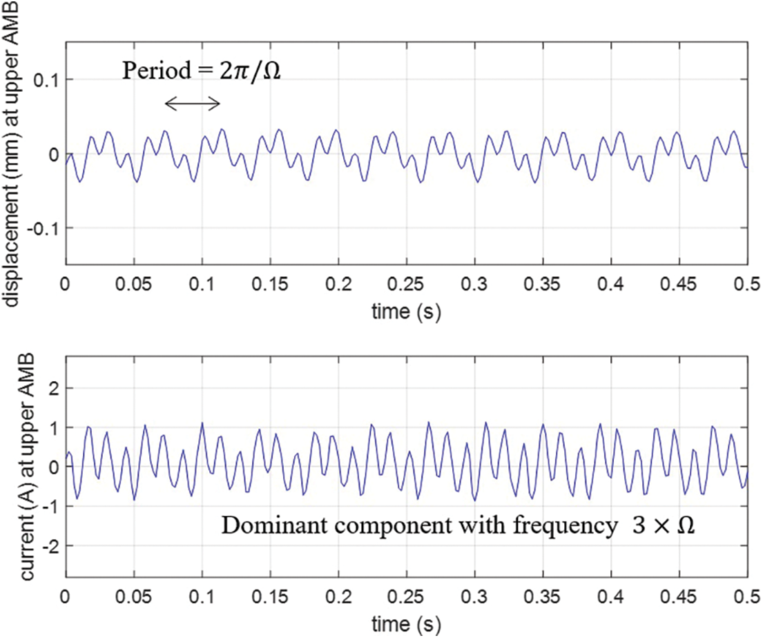
Figure 6: Measured rotor vibration and current at upper AMB with PD controller (Ω = 150 rad/s)
4.2 H-Infinity Controller Design
The H-infinity controller design approach involves appending the closed loop system description with stable weighting transfer functions. This leads to an ‘augmented plant’ description which is depicted in Fig. 7. The H-infinity controller solution, which can be calculated using standard state-space methods [19], provides a controller (if one exists) that makes the closed loop system have an H-infinity norm less than
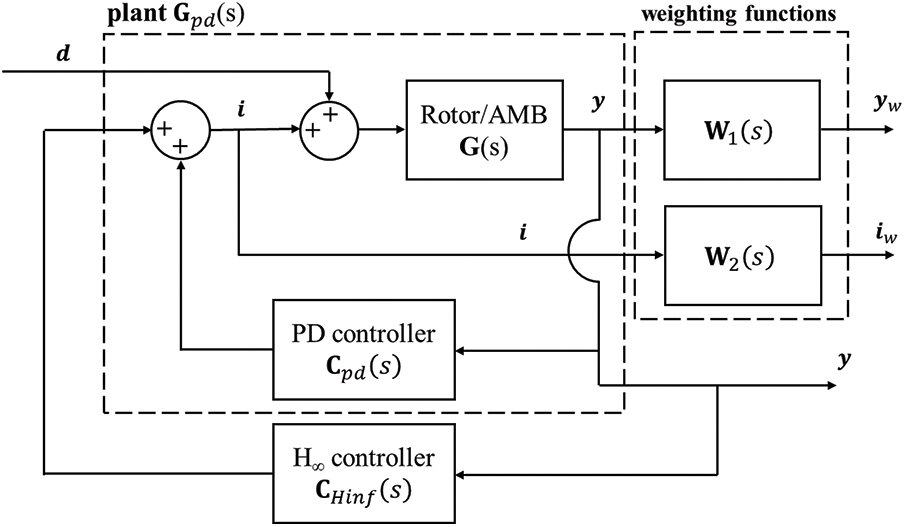
Figure 7: Definition of closed loop system T including design weighting functions
This implies the closed loop system has two important properties:
1.
2. Bounded frequency response:
As the calculation of the controller solution
The weighting function
The case of the PD-controlled system was used as a reference to select the initial choice of weighting functions, because the PD controller works well at zero speed and has suitable stiffness and noise attenuation characteristics. The H-infinity controller will work together in parallel with the PD controller to improve the stability of the nutation mode and also to filter harmonic excitation components from the control currents. For this configuration, the PD controller may still be operated alone over a low speed range (Ω = 0–150 rad/s).
The weighting function acting on the displacement output
Two cases are considered
where,
Controller solutions were calculated for fixed values of rotational speed
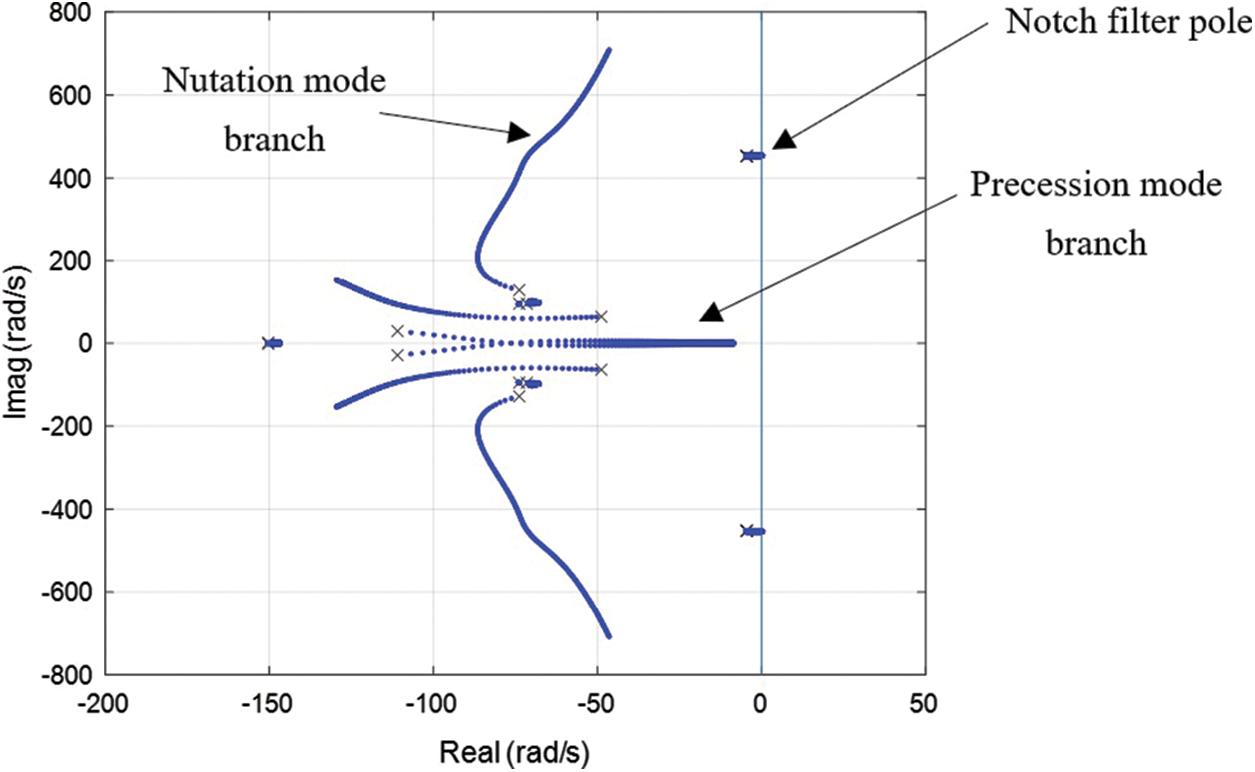
Figure 8: Root locus for H-infinity controller A (single notch filter) for speed range Ω = 150 to 400 rad/s
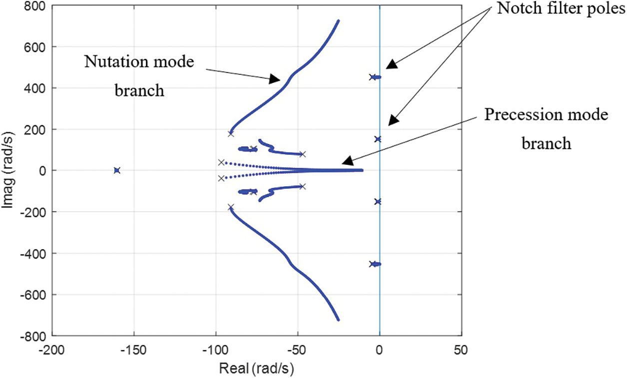
Figure 9: Root locus for H-infinity controller B (double notch filter) for speed range Ω = 150 to 400 rad/s
The behaviors of the controllers can also be assessed from the closed loop frequency response characteristics. The singular values of the closed loop system are shown in Fig. 10 for both vibration control performance
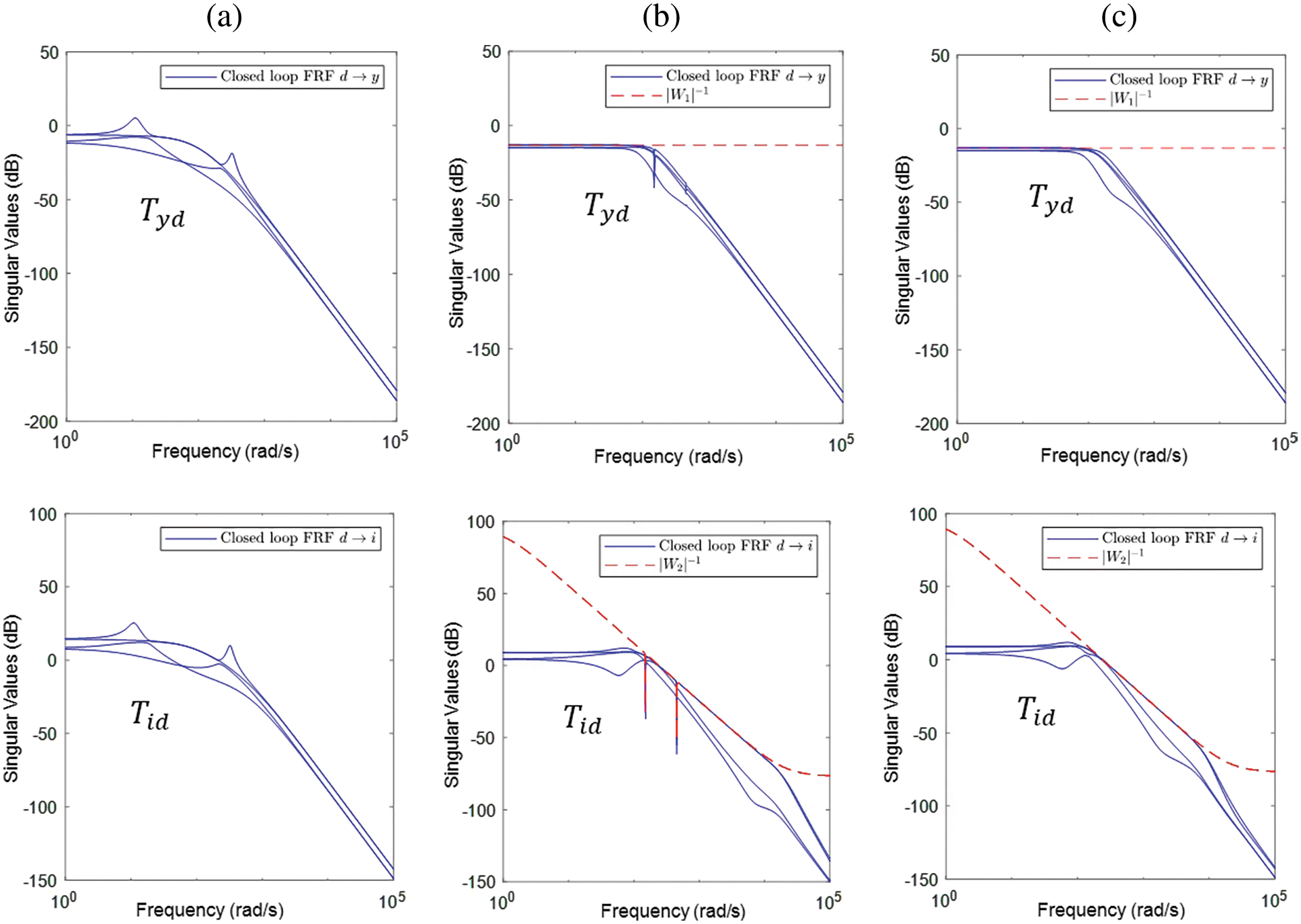
Figure 10: Frequency response function (singular values) of closed loop system for rotation speed Ω = 150 rad/s with (a) PD controller (b) H-infinity controller-double notch filters (c) H-infinity controller-no notch filters
To assess the performance of the controllers experimentally, direct measurements of the system frequency response characteristics were made. This involved applying sine wave excitations through the AMB coil currents, with measurements made of the magnitude and phase of the rotor displacement response. Fig. 11 shows the frequency response of the closed loop system for a rotational speed Ω = 150 rad/s. For the PD controller, the frequency response data shows clear resonance spikes due to excitation of the rotor precession and nutation modes, although the nutation mode (having natural frequency of 52 Hz) is stable for this speed. In practice, the onset speed for instability was found to be lower than predicted by the theoretical model. This is most probably due to unmodeled time delay and lag effects in the experimental implementation, including possible magnetic hysteresis effects. Results from frequency response testing with the H-infinity controllers show clearly that stability of the nutation mode is improved, when compared with the PD controller, as the resonance close to 52 Hz is eliminated. Case B with double-resonance filter was found to be more effective at controlling excitation of the precession mode for this rotational speed.
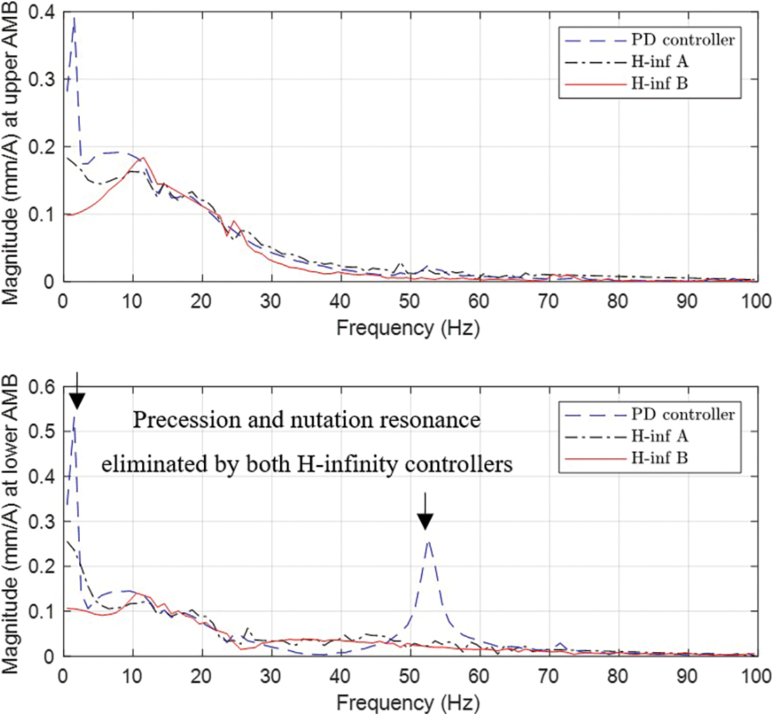
Figure 11: Measured frequency response of flywheel-AMB system at speed of
Table 3 shows the AMB power consumption figures for operation at the controller’s designed speed of Ω = 150 rad/s. For H-infinity controller Case A, which filters only the

Fig. 12 shows the measured rotor displacements and AMB currents during system operation with speed of Ω = 150 rad/s. The H-infinity controller caused an increase in vibration of the rotor, which is an unavoidable side-effect of the reduction in current levels. However, the peak rotor displacements remained within acceptable levels (less than 0.07 mm). Fig. 13 shows the Fourier transform of the coil currents measured at the lower AMB. With H-infinity controller Case B. There is a clear reduction in the amplitude of the components with frequencies of 1 and 3 times the rotational speed. The amplitudes of the other frequency components remain similar to the case with PD control. For these results, the set-point/offset for the position signals correspond to the center of the bearing, which also matches the zero-current equilibrium position.
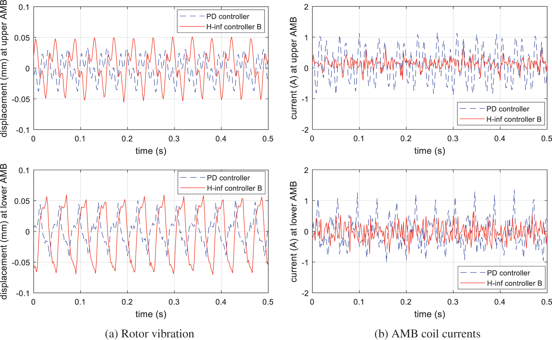
Figure 12: Rotor displacements and AMB coil currents when operating with Ω = 150 rad/s for cases with PD control and H-infinity controller B
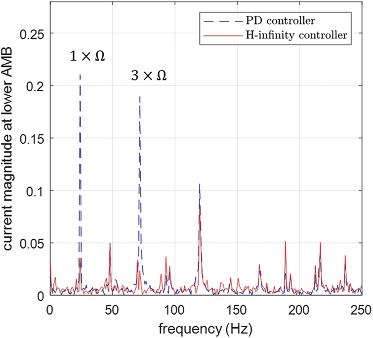
Figure 13: Fourier transform of coil current at lower AMB when Ω = 150 rad/s, showing comparison of PD controller and H-infinity controller B
This paper has presented a theoretical and experimental study on controller design for the AMBs in a small-scale FESS. The main novelty in the work is the application of the H-infinity optimal design methodology to a 4-DOF, PM-biased radial AMB system, with the main objective of minimizing operating power consumption. A key advantage of the approach is that a complete and effective controller solution can be produced using a well-defined model-based control synthesis procedure, thereby avoiding the need for add-on and/or ad-hoc control implementations. Experimental tests were used to validate the controller design methodology and provide comparative results on performance and efficiency. According to test findings, the H-infinity controller is able to achieve stable rotor levitation and reduce AMB power consumption by more than 40% (from 4.80 to 2.64 Watts) compared with a conventional PD control method. Additionally, the H-infinity controller could prevent vibrational instability of the rotor nutation mode, which is prone to occur when operating with high rotational speeds.
A drawback of the H-infinity control design method, in standard form, is that the controller must be synthesized for a specific constant rotational speed. To expand the speed range for operation and achieve speed tracking of the notch filter, further work will consider the gain-scheduled H-infinity control method. This can be applied based on the speed-dependent linear parameter varying (LPV) model of the system dynamics [20]. In this way, both the filtering characteristics and stabilizing properties of the H-infinity controller can be varied continuously to match the rotational speed, potentially up to much higher values than were considered in the present study.
Acknowledgement: The authors gratefully acknowledge the support of Boonyawat Teeraprawatekul and Tharanon Usana-Ampaipong of Acme International (Thailand) Co. in the design and manufacture of the prototype FESS.
Funding Statement: This work was supported by Thailand Science Research and Innovation and the National Research Council of Thailand under Grant RGU6280014.
Conflicts of Interest: The authors declare that they have no conflicts of interest to report regarding the present study.
References
1. Arabkoohsar, A. (2020). Mechanical energy storage technologies. Cambridge, MA, USA: Academic Press. [Google Scholar]
2. Faraji, F., Majazi, A., Al-Haddad, K. (2017). A comprehensive review of flywheel energy storage system technology. Renewable and Sustainable Energy Reviews, 67(1), 477–490. DOI 10.1016/j.rser.2016.09.060. [Google Scholar] [CrossRef]
3. Pena-Alzola, R., Sebastián, R., Quesada, J., Colmenar, A. (2011). Review of flywheel based energy storage systems. Proceedings of 2011 International Conference on Power Engineering, Energy and Electrical Drives, pp. 1–6. Torremolinos (Málaga), Spain. [Google Scholar]
4. Hadjipaschalis, I., Poullikkas, A., Efthimiou, V. (2009). Overview of current and future energy storage technologies for electric power applications. Renewable and Sustainable Energy Reviews, 13(6–7), 1513–1522. DOI 10.1016/j.rser.2008.09.028. [Google Scholar] [CrossRef]
5. Suvire, G. O., Molina, M. G., Mercado, P. E. (2012). Improving the integration of wind power generation into AC microgrids using flywheel energy storage. IEEE Transactions on Smart Grid, 3(4), 1945–1954. DOI 10.1109/TSG.2012.2208769. [Google Scholar] [CrossRef]
6. Liu, H., Jiang, J. (2007). Flywheel energy storage-an upswing technology for energy sustainability. Energy and Buildings, 39(5), 599–604. DOI 10.1016/j.enbuild.2006.10.001. [Google Scholar] [CrossRef]
7. Li, X., Anvari, B., Palazzolo, A., Wang, Z., Toliyat, H. (2017). A utility-scale flywheel energy storage system with a shaftless, hubless, high-strength steel rotor. IEEE Transactions on Industrial Electronics, 65(8), 6667–6675. DOI 10.1109/TIE.2017.2772205. [Google Scholar] [CrossRef]
8. Filatov, A., Hawkins, L., McMullen, P. (2016). Homopolar permanent-magnet-biased actuators and their application in rotational active magnetic bearing systems. Actuators, 5(4), 26. DOI 10.3390/act5040026. [Google Scholar] [CrossRef]
9. Kiani M., Salarieh H., Alasty A., Darbandi S. M. (2016). Hybrid control of a three-pole active magnetic bearing. Mechatronics, 39(4), 28–41. DOI 10.1016/j.mechatronics.2016.07.004. [Google Scholar] [CrossRef]
10. Zhao, W., Mei, L. (2021). Research on modular permanent magnet bias magnetic bearing. Proceedings of 24th International Conference on Electrical Machines and Systems, pp. 1582–1587. Gyeongju, Korea. [Google Scholar]
11. Zheng, S., Li, H., Han, B., Yang, J. (2017). Power consumption reduction for magnetic bearing systems during torque output of control moment gyros. IEEE Transactions on Power Electronics, 32(7), 5752–5759. DOI 10.1109/TPEL.2016.2608660. [Google Scholar] [CrossRef]
12. Wang, H., Wu, Z., Liu, K., Wei, J., Hu, H. (2022). Modeling and control strategies of a novel axial hybrid magnetic bearing for flywheel energy storage system. IEEE/ASME Transactions on Mechatronics. DOI 10.1109/TMECH.2022.3145705. [Google Scholar] [CrossRef]
13. Ahrens, M., Kucera, L., Larsonneur, R. (1996). Performance of a magnetically suspended flywheel energy storage device. IEEE Transactions on Control Systems Technology, 4(5), 494–502. DOI 10.1109/87.531916. [Google Scholar] [CrossRef]
14. Fang, J., Ren, Y., Fan, Y. (2013). Nutation and precession stability criterion of magnetically suspended rigid rotors with gyroscopic effects based on positive and negative frequency characteristics. IEEE Transactions on Industrial Electronics, 61(4), 2003–2014. DOI 10.1109/TIE.2013.2266077. [Google Scholar] [CrossRef]
15. Sun, M., Zheng, S., Wang, K., Le, Y. (2019). Filter cross-feedback control for nutation mode of asymmetric rotors with gyroscopic effects. IEEE/ASME Transactions on Mechatronics, 25(1), 248–258. DOI 10.1109/TMECH.2019.2953329. [Google Scholar] [CrossRef]
16. Dong, S. C., Fang, J. C., Yu, W. B. (2004). Nutation stability study of flywheel rotor supported by AMB. IFAC Proceedings Volumes, 37(6), 805–808. [Google Scholar]
17. Chen, J. F., Liu, K., Chen, X. F. (2011). Modeling and low power control of active magnetic bearings system. Proceedings of 2011 International Conference on Modelling, Identification and Control, pp. 319–324. Shanghai, China. [Google Scholar]
18. Schweitzer, G., Maslen, E. H. (2009). Magnetic bearings. Theory, design, and application to rotating machinery. Berlin, Heidelberg: Springer. [Google Scholar]
19. Zhou, K., Doyle, J. C., Glover, K. (1996). Robust and optimal control. Upper Saddle River, NJ, USA: Prentice Hall. [Google Scholar]
20. Balini, H. M. N. K., Witte, J., Scherer, C. W. (2012). Synthesis and implementation of gain-scheduling and LPV controllers for an AMB system. Automatica, 48(3), 521–527. DOI 10.1016/j.automatica.2011.08.061. [Google Scholar] [CrossRef]
Cite This Article
 Copyright © 2023 The Author(s). Published by Tech Science Press.
This work is licensed under a Creative Commons Attribution 4.0 International License , which permits unrestricted use, distribution, and reproduction in any medium, provided the original work is properly cited.
 Downloads
 Citation Tools